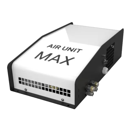
Summary of Contents for hydrotab AIR UNIT MAX
- Page 1 Hydro Hydro Marine Engineering Marine Engineering INSTALLATION MANUAL NMEA 2000 NMEA 0183 Hydrotab BT Series AIR UNIT MAX...
-
Page 2: Disclaimer
Trademark Notice Hydrotab is a registered trademark of Fair use statement Olympic Engineering Ltd, Greece. All other This manual can be printed or copied for trademarks, trade names or company your own use only. -
Page 3: Table Of Contents
Air Unit Max Installation Pneumatic Connection Technical Data + Dimensions Air Unit Max Direct Installation Diagram Air Unit Max Installation Diagram on existing NMEA network Air Unit Max Electrical Diagram Air Unit Max Pneumatic Diagram Spare Parts Spare Parts - Valves Assembly... -
Page 4: Air Unit Max Installation
Air Unit upside-down You will need Drill Ø3 Fig.1: Find a clear surface, place the Air Unit Fig.2: Make holes with Ø3 drill. Max, and mark the holes with a pencil. M4,8x25 Fig.3: Mount the Air Unit Max with the given screws. -
Page 5: Pneumatic Connection
Pneumatic Connection 4. Connect the push-in fitting 5. Cut the 8mm pipe at the proper length and connect it to the Air Unit Technical Data & Dimensions Air Unit Max DataSheet Compressor power 380 W Air compressor type Brushless, oil-free Voltage... -
Page 6: Air Unit Max Direct Installation Diagram
Hydro Marine Engineering Direct Installation Diagram Moby Controller Air Unit Max Flybridge OPTIONAL controller USE INLINE TERMINATOR CABLE TO 30A 3m - MF FUSE CABLE CABLE 10m - MF 10m - FF In case a new NMEA 2000 instrument to be added, a proper NMEA Network must be built. -
Page 7: Air Unit Max Electrical Diagram
Air Unit Max Electrical Diagram Air Unit Max Pneumatic Diagram Compressor NM E A 2000 VALVE GROUP 500.AIR-N2Κ-ΤΗ-V2.1 CAN-H CAN-L -12/24V RM+12V -12/24V +12/24V F1 F1 Switch + - +12V Battery Compressor Timer (PNE-01242A) IMPORTANT: THE SWITCHES MUST BE STRICTLY SET... -
Page 8: Spare Parts
Hydro Marine Engineering Spare Parts - Air Unit Max Valves Assembly (see below) BOM ID PartNo Description QTY. BOM ID PartNo Description QTY. ELE-00535 5PIN PCB MALE CONNECTOR PNE-01242A COMPRESSOR MINI USB PORT, FEMALE PNE-01242B TRASNFORMER ELE-00647 ELE-00698 RELAY TIMER... -
Page 9: Troubleshooting
Hydro Marine Engineering Troubleshooting Moby Controller is Moby Controller is ON but flaps do not ON but flaps do not operate on manual operate on manual Go to System Information. Do you notice N2K error and Temperature Offline? 1) Open the air unit. 1) Is there power supply 2) When buttons ↑↓←→... -
Page 10: Warranty Conditions
Hydrotab's warranty only covers the repair or replacement of spare parts. System selections It is the sole responsibility of the buyer to choose the correct system and even with Hydrotab’s suggestion for a system, the overall responsibility is with the buyer. - Page 11 Hydro Marine Engineering Notes...
- Page 12 Hydro Marine Engineering Hydro 4, Papazoglou str. GR-17778 Athens Greece email: info@hydrotab.gr Marine Engineering website: www.hydrotab.gr REV.C...


Need help?
Do you have a question about the AIR UNIT MAX and is the answer not in the manual?
Questions and answers