Sign In
Upload
Download
Add to my manuals
Delete from my manuals
Share
URL of this page:
HTML Link:
Bookmark this page
Add
Manual will be automatically added to "My Manuals"
Print this page
×
Bookmark added
×
Added to my manuals
Manuals
Brands
HOMCOM Manuals
Fitness Equipment
A90-105
Assembly instructions manual
HOMCOM A90-105 Assembly Instructions Manual
Hide thumbs
1
2
3
4
5
6
7
8
9
10
11
page
of
11
Go
/
11
Bookmarks
Advertisement
Quick Links
Download this manual
INade073V01_UK
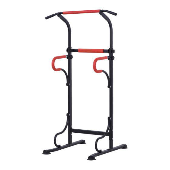
A90-105
warm tips :please read the instruction carefully before using the product and keep it
properly.
READ AND SAVE THESE INSTRUCTIONS FOR FUTURE USE
ASSEMBLY INSTRUCTION
Previous
Page
Next
Page
1
2
3
4
5
Advertisement
Need help?
Do you have a question about the A90-105 and is the answer not in the manual?
Ask a question
Questions and answers
Related Manuals for HOMCOM A90-105
Fitness Equipment HOMCOM A90-179 User Manual
Mini trainer (4 pages)
Fitness Equipment HOMCOM A90-144 Instruction Manual
Spinning bike (8 pages)
Fitness Equipment HOMCOM A90-137 User Manual
Airwalkertrainer (7 pages)
Fitness Equipment HOMCOM A90-142 User Manual
Smart multifunctional sit up bench (5 pages)
Fitness Equipment HOMCOM A90-143 User Manual
Smart multifunctional sit up bench (10 pages)
Fitness Equipment HOMCOM A90-193 Assembly Instruction Manual
(10 pages)
Fitness Equipment HOMCOM A90-128 Instruction Manual
Stepper (18 pages)
Fitness Equipment HOMCOM A90-190 Assembly Instructions Manual
(15 pages)
Fitness Equipment HOMCOM A90-192 Assembly & Instruction Manual
(21 pages)
Fitness Equipment HOMCOM A90-245 Assembly Instruction Manual
(17 pages)
Fitness Equipment HOMCOM A90-262 Assembly & Instruction Manual
(6 pages)
Fitness Equipment HOMCOM A90-279 Assembly & Instruction Manual
Stepper (24 pages)
Fitness Equipment HOMCOM A90-276 Assembly & Instruction Manual
(17 pages)
Fitness Equipment HOMCOM A90-310 Using Instruction
(10 pages)
Fitness Equipment HOMCOM A90-313 Using Instruction
(21 pages)
Fitness Equipment HOMCOM A90-296 Manual
(11 pages)
This manual is also suitable for:
A91-105
Print
Rename the bookmark
Delete bookmark?
Delete from my manuals?
Login
Sign In
OR
Sign in with Facebook
Sign in with Google
Upload manual
Upload from disk
Upload from URL


Need help?
Do you have a question about the A90-105 and is the answer not in the manual?
Questions and answers