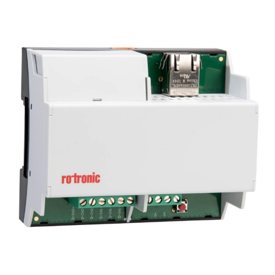
Rotronic HygroClip2 ADVANCED Manual

Rotronic HygroClip2 ADVANCED Manual

Rms digital input module
Hide thumbs Also See for HygroClip2 ADVANCED:

Advertisement

Quick Links

RMS Digital Input Module
© 2017
ROTRONIC AG
Bassersdorf
Switzerland

Advertisement

Table of Contents
loading

Summary of Contents for Rotronic HygroClip2 ADVANCED

  • Page 1 RMS Digital Input Module    © 2017 ROTRONIC AG Bassersdorf Switzerland...
  • Page 2: Table Of Contents

    Integration in the RMS-WEB Software ....................15 Function Overview ..........................17 Maintenance ............................18 Battery Replacement .......................... 18 Firmware Update..........................18 Technical Specifications ........................19 Additional Documents ......................... 21 Document Version ..........................22    © 2018 ROTRONIC AG Bassersdorf Switzerland Page 2 of 22...
  • Page 3: Overview

    RMS System Overview The Rotronic Monitoring System (RMS) is a network comprising various devices and the RMS server software. The software is the heart of the system. It collects all measured data of the devices and saves it in the database.
  • Page 4: Device Overview

    The gateway is the connecting element between Ethernet and wireless network and forwards the data flow from the loggers to the data centre. Except for the Mini Logger    © 2018 ROTRONIC AG Bassersdorf Switzerland Page 4 of 22...
  • Page 5: Rms Digital Input Module

    Only batteries of the same type or with identical characteristic values may be used as replacement batteries. 1.4.1 Type of Battery Battery Specifications Article RMS-BAT (please see for Details www.rotronic.com) Type Li-SOCl2 Capacitance 2100 mAh Voltage 3.6 V...
  • Page 6: Inputs / Outputs

    The recording of measured data is always active when the device is integrated in a RMS-WEB system and thus continuous measurements are carried out. Following measured values are saved: time stamp actual status of the digital inputs    © 2018 ROTRONIC AG Bassersdorf Switzerland Page 6 of 22...
  • Page 7: Operating And Display Elements

    1x orange, measurement succesful, data the input transfer failed 1x red, low battery (only by battery powered) Interface The device is operated completely via the LAN interface.    © 2018 ROTRONIC AG Bassersdorf Switzerland Page 7 of 22...
  • Page 8: 1.10 Modbus Communication Protocol

    Unsigned 32 Bit SN in Hex: e.g. 01ACCBE1 = 28101601 If no communication is performed for more than 30 seconds, the device automatically closes the  TCP connection.    © 2018 ROTRONIC AG Bassersdorf Switzerland Page 8 of 22...
  • Page 9: Dimensions

    RMS Digital Input Module Instruction Manual E-M-RMS-DI-V1_1.docx Dimensions Figure 2: Side view from left of DIN rail housing Figure 3: Front view of DIN rail housing    © 2018 ROTRONIC AG Bassersdorf Switzerland Page 9 of 22...
  • Page 10: Installation

    Please remove this yellow stick to turn on the battery supply. If you don’t remove this stick, you will not be able to record data if the power supply is interrupted.    © 2018 ROTRONIC AG Bassersdorf Switzerland Page 10 of 22...
  • Page 11: Electrical Connections

    D-IN1+ D-IN1- D-IN1+R D-IN2+ D-IN2- D-IN2+R IN1 Reed contact- contact + 5…24V IN1 Input IN2 Reed contact - contact + 5…24V IN2 Input    © 2018 ROTRONIC AG Bassersdorf Switzerland Page 11 of 22...
  • Page 12: Behavior Of The Inputs

    Lithium batteries of the type AA with 3.6 V are used, per section 1.4.1. Make sure they are inserted correctly. The poles are marked on the battery and in the battery compartment.    © 2018 ROTRONIC AG Bassersdorf Switzerland Page 12 of 22...
  • Page 13: Operation

    Configuration of the LAN Devices with RMS-CONFIG If you do not want to connect the device to the Rotronic Cloud, the server must be configured in the device.  Connect the device to the local network as described in section 3 . Start the RMS configuration software.
  • Page 14 Once they have been configured with the correct server address, the devices can then be integrated into the server software. Details are described in the manual E-SM-RMS-WEB.    © 2018 ROTRONIC AG Bassersdorf Switzerland Page 14 of 22...
  • Page 15: Integration In The Rms-Web Software

    The devices can also be given a static IP address if there is no DHCP server available in the network. Integration of the device (Pairing) in 6 Steps If you do not want to connect the device to the Rotronic Cloud, the server must be configured in the device.
  • Page 16 RMS Digital Input Module Instruction Manual E-M-RMS-DI-V1_1.docx Configure the device. Finish configuration. You can find details in the instruction manual for the RMS server software: E-SM-RMS-WEB    © 2018 ROTRONIC AG Bassersdorf Switzerland Page 16 of 22...
  • Page 17: Function Overview

    (75,000 measured values). ►Firmware update The firmware of the device can be updated directly via the RMS server software.    © 2018 ROTRONIC AG Bassersdorf Switzerland Page 17 of 22...
  • Page 18: Maintenance

    System message in the RMS server software The following steps are necessary to replace the battery:  Press the front flap of the housing, which is labeled with Rotronic, with a very narrow object.  Remove the old battery and insert a new one The time setting of the data logger is synchronized automatically after the battery replacement.
  • Page 19: Technical Specifications

    Polarity protection Current consumption <100 mA Battery life ~2 years (at 23 °C) Power supply requirements: 24 VDC ±10 % / >4 W / limited power source    © 2018 ROTRONIC AG Bassersdorf Switzerland Page 19 of 22...
  • Page 20 2014/30/EU EN 55011 IEC CISPR 11 EN 55032 IEC CISPR 32 LVD- directives: EN 61010-1 IEC 61010-1 2014/35/EU Performance criterion: www.rotronic.com RoHS-directives: EN 50581 2014/65/EU Soldering material: Lead free FDA / GAMP FDA CFR21 Part 11 / GAMP5 directives ...
  • Page 21: Additional Documents

    RMS Digital Input Module Instruction Manual E-M-RMS-DI-V1_1.docx Additional Documents Document Name Contents E-IM-RMS-WEB Instruction Manual: System Installation E-SM-RMS-WEB Instruction Manual: System Startup E-OM-RMS-WEB Instruction Manual: System Operation    © 2018 ROTRONIC AG Bassersdorf Switzerland Page 21 of 22...
  • Page 22: Document Version

    RMS Digital Input Module Instruction Manual E-M-RMS-DI-V1_1.docx Document Version Version Date Notes V1_0 August 2017 First version V1_1 February2018 Revision    © 2018 ROTRONIC AG Bassersdorf Switzerland Page 22 of 22...

This manual is also suitable for:

Hc2a

Table of Contents