Table of Contents
Advertisement
Quick Links
© Copyright 2017
EVERTZ MICROSYSTEMS LTD.
5292 John Lucas Drive,
Burlington, Ontario,
Canada L7L 5Z9
Phone:
+1 905-335-3700
Sales:
sales@evertz.com
Tech Support: service@evertz.com
Web Page:
http://www.evertz.com
Version 1.0, November 2017
The material contained in this user manual consists of information that is the property of Evertz Microsystems and is intended solely for the use of
purchasers of the 7800EMR-ALINK2 product. Evertz Microsystems expressly prohibits the use of this guide for any purpose other than the
operation of the contained in this reference guide consists of information that is the property of Evertz Microsystems and is intended solely for the
use of purchasers of the 7800EMR-ALINK2 product. Due to on going research and development, features and specifications in this manual are
subject to change without notice.
All rights reserved. No part of this publication may be reproduced without the express written permission of Evertz Microsystems Ltd. Copies of
this manual can be ordered from your Evertz dealer or from Evertz Microsystems.
7800EMR-ALINK2
User Manual
Fax: +1 905-335-3573
Fax: +1 905-335-7571
Advertisement
Table of Contents

Related Manuals for evertz 7800EMR-ALINK2


Summary of Contents for evertz 7800EMR-ALINK2
- Page 1 Version 1.0, November 2017 The material contained in this user manual consists of information that is the property of Evertz Microsystems and is intended solely for the use of purchasers of the 7800EMR-ALINK2 product. Evertz Microsystems expressly prohibits the use of this guide for any purpose other than the operation of the contained in this reference guide consists of information that is the property of Evertz Microsystems and is intended solely for the use of purchasers of the 7800EMR-ALINK2 product.
- Page 2 This page left intentionally blank...
- Page 3 IMPORTANT SAFETY INSTRUCTIONS The lightning flash with arrowhead symbol within an equilateral triangle is intended to alert the user to the presence of un-insulated “Dangerous voltage” within the product’s enclosure that may be of sufficient magnitude to constitute a risk of electric shock to persons. The exclamation point within an equilateral triangle is intended to alert the user to the presence of important operating and maintenance (Servicing) instructions in the literature accompanying the product.
- Page 4 WARNING Changes or Modifications not expressly approved by Evertz Microsystems Ltd. could void the user’s authority to operate the equipment. Use of unshielded plugs or cables may cause radiation interference. Properly shielded interface cables...
-
Page 5: Table Of Contents
2.3. CONTROL ..........................3 2.4. REFERENCE ........................3 2.5. FRAMES ..........................3 INSTALLATION ..........................5 3.1. INSTALLATION OF 7800EMR-ALINK2 ON 7800FR FRAME ..........5 FRONT CARD EDGE CONTROLS AND LEDS ................7 SERIAL MENU ..........................9 5.1. NETWORK CONFIGURATION ................... 10 5.2. - Page 6 Figures Figure 1-1: Block Diagram - 7800EMR-ALINK2 ....................1 Figure 1-2 : Redundant Mode vs. Dual Port Mode Rear Panel Configuration - 7800EMR-ALINK2 ....2 Figure 3-1 : 7800EMR-ALINK2 Rear Plate ...................... 5 Figure 4-1 : Front Card Edges of 7800EMR-ALINK2 ..................7 Figure 5-1 : COM Port Settings ........................
- Page 7 Evertz products are for informational use only and are not warranties of future performance, either expressed or implied. The only warranty offered by Evertz in relation to this product is the Evertz standard limited warranty, stated in the sales contract or order confirmation form.
- Page 8 7800EMR-ALINK2 User Manual This page left intentionally blank Page - iv Revision 1.0...
-
Page 9: Overview
The 7800EMR-ALINK2 provides a means of a bulk audio interconnection from a Studer A-Link interface to TDM for Evertz EMR and EQX Audio products using TDM backbone. There are 2 paired TDM links (both TX and RX) for one A-Link bidirectional interface. This is the case for both independent paths that can be configured to function in a master-slave mode or a dual independent path mode. -
Page 10: Dual Port Mode Vs Redundant Mode Operation
TDM input on each A-Link port is not operational. All TDM outputs remain operational in either Dual Port Mode or Redundant Mode Figure 1-2 : Redundant Mode vs. Dual Port Mode Rear Panel Configuration - 7800EMR-ALINK2 Page - 2 Revision 1.0... -
Page 11: Specifications
7800EMR-ALINK2 User Manual SPECIFICATIONS 2.1. AUDIO INPUTS Number of TDM Inputs 4 x DIN Number of TDM Outputs 4 x DIN Connector BNC per IEC 61169-8 Annex A, DIN 1.0/2.3 75 Ω terminating Impedance 2.2. A-LINK INPUTS/OUTPUTS Number of A-LINK Inputs... - Page 12 7800EMR-ALINK2 User Manual This page left intentionally blank Page - 4 Revision 1.0...
-
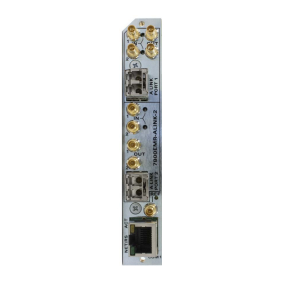
Page 13: Installation
Before handling the card it is important to minimize the potential effects of static electricity. It is therefore recommended that an ESD strap to be worn. 7800EMR-ALINK2 module must have minimum 1 slot vacant in the frame. Each rear plate can house one 7800EMR-ALINK2 module. - Page 14 7800EMR-ALINK2 User Manual This page left intentionally blank Page - 6 Revision 1.0...
-
Page 15: Front Card Edge Controls And Leds
User Manual FRONT CARD EDGE CONTROLS AND LEDS The 7800EMR-ALINK2 front card edges have some key controls and indicators that can help in the installation and debugging processes. Figure 4-1 shows the card edges and describes the expected behavior of each component. - Page 16 7800EMR-ALINK2 User Manual This page left intentionally blank Page - 8 Revision 1.0...
-
Page 17: Serial Menu
SERIAL MENU To determine or set IP address using the serial port, Connect DB9 cable between the COM port on the 7800EMR-ALINK2 (J6) and the computer. Start the terminal program and configure the ports settings with the parameters in Figure 5-1. -
Page 18: Network Configuration
7800EMR-ALINK2 User Manual 5.1. NETWORK CONFIGURATION Set IP Address Allows the user to set the IP address. Set Netmask Allows the user to set the Netmask address. Set Gateway Allows the user to set the Gateway address. Set Broadcast Allows the user to set the Broadcast address. -
Page 19: A-Link Mode Configuration
7800EMR-ALINK2 User Manual TDM Tone Generator Menu View Tone Gen Allows the user to view the gain status of tone gen Gain/Enable per channel. View Tone Gen Allows the user to view the status of tone gen per Status Info channel. - Page 20 7800EMR-ALINK2 User Manual This page left intentionally blank Page - 12 Revision 1.0...
-
Page 21: Vistalink
IP address of 7800EMR-ALINK2 and right click to “View Configuration...” Depending on which mode the 7800EMR-ALINK2 is set to, the tab menu options in VistaLINK® PRO differ slightly. In section 6.1 and 6.2 both dual port mode and redundancy mode tab menus will be outlined respectively. - Page 22 7800EMR-ALINK2 User Manual Reference For Port 1 and Port2 Video Standard: Allows selecting the reference Standard from NTSC, PAL or Auto. Present: Displays whether the Video reference is Present or Absent. Video Standard: Displays the standard of the Video Reference.
-
Page 23: A-Link Control
7800EMR-ALINK2 User Manual 6.1.2. A-LINK CONTROL The A-Link Control section displays the status, control and A-Link Tone Generator. Figure 6-2 : Dual Port Mode - VistaLINK - ALINK ® Page - 15 Revision 1.0... - Page 24 7800EMR-ALINK2 User Manual Input Status For A-Link Port 1 and Port 2 A-Link Input Active: Displays whether there is a valid A-LINK Input or not A-Link Input Locked: Displays whether the A-LINK is Locked or not A-Link Input Quality: Displays the quality of the A-LINK Source A-Link Input Port: Displays the port # of the A-LINK Source A-Link Input Channels Received: Displays the # of input channels received.
-
Page 25: Tdm Control
7800EMR-ALINK2 User Manual 6.1.3. TDM CONTROL The TDM Control section displays the TDM Status and TDM Tone Generator. Figure 6-3 : Dual Port Mode - VistaLINK - TDM Control ® Page - 17 Revision 1.0... - Page 26 7800EMR-ALINK2 User Manual TDM Input 1 of A-Link Port 1 TDM Input Present 1: Displays whether the TDM Signal is detected on TDM Input 1 of A-Link Port 1. TDM Input SID Present 1: Displays whether the TDM Signal has Source ID or not.
- Page 27 7800EMR-ALINK2 User Manual Output SID Status TDM Output SID IP Address: Displays the IP Address of 7800EMR-A-LINK 2. TDM Output SID Port Number: Displays the TDM Output Port # of 7800EMR-A-LINK 2. TDM Output SID Description: Displays the description of outgoing TDM.
-
Page 28: Monitor Status
7800EMR-ALINK2 User Manual 6.1.4. MONITOR STATUS The Monitor Status section allows the user to monitor the status of A-LINK and TDM Signal and also the audio. Figure 6-4 : Dual Port Mode - VistaLINK - Monitor Status ® TDM & A-LINK Channel 1&2 of A-LINK Port 1&2 Show Channels for TDM &... -
Page 29: Audio Mono Config
7800EMR-ALINK2 User Manual 6.1.5. AUDIO MONO CONFIG The Audio Mono Config section allows the user to set the audio fault threshold for TDM and A-Link ports. Figure 6-5 : Dual Port Mode - VistaLINK - Audio Mono Config ® Page - 21... - Page 30 7800EMR-ALINK2 User Manual TDM Audio Fault Definition for Channel 1 & 2 of Port 1 & 2 Show TDM Fault Definition Channel: Allows the user to select the mono channels to set the fault definitions. Apply button: Apply button is to set the mono channel 1 settings to rest of the mono channels.
-
Page 31: Audio Stereo Config
7800EMR-ALINK2 User Manual 6.1.6. AUDIO STEREO CONFIG The Audio Stereo Config section allows the user to set the audio fault threshold for TDM and A-Link ports. Figure 6-6 : Dual Port Mode - VistaLINK - Audio Stereo Config ® TDM Audio Fault Definition for Port 1&2 Show TDM Fault Definition Channel: Allows the user to select the TDM stereo channel to set the fault definitions. - Page 32 7800EMR-ALINK2 User Manual TDM Audio Definition for Port 1&2 Show A-Link Fault Definition Channel: Allows the user to select the A-Link stereo channel to set the fault definitions. Apply Button: Apply button is to set the TDM stereo channel 1/2 settings to rest of the stereo channels.
-
Page 33: Audio Channel Faults
7800EMR-ALINK2 User Manual 6.1.7. AUDIO CHANNEL FAULTS The Audio Pair Faults section allows the user to Enable or Disable the Phase Reversal traps and Mono traps. Figure 6-7 : Dual Port Mode - VistaLINK - Audio Channel Faults ® Show TDM Audio Fault Channels: Allows the user to select the TDM channels to enable the traps. - Page 34 7800EMR-ALINK2 User Manual TDM Fault Status For A-Link Port 1 & 2 Audio Channel Loss: Option to display whether the audio is Lost. Audio Channel Silent: Option to display whether the audio is silent. Audio Channel Over: Option to display whether the audio is over.
-
Page 35: Audio Channel Pair Faults
7800EMR-ALINK2 User Manual 6.1.8. AUDIO CHANNEL PAIR FAULTS The Audio Pair Faults section allows the user to Enable or Disable the Phase Reversal traps and Mono traps. Figure 6-8 : Dual Port Mode VistaLINK - Audio Channel Pair Faults ®... - Page 36 7800EMR-ALINK2 User Manual Trap Status: Mono: Status monitor displays fault condition on the audio pairs. Green indicates no faults while red indicates a triggered fault condition. A-Link Channels for A-Link Port 1 & Port 2 Show Audio Fault Channels: Allows the user to select which A-Link channels to enable traps on.
-
Page 37: Redundancy Mode
7800EMR-ALINK2 User Manual 6.2. REDUNDANCY MODE When the 7800EMR-ALINK2 is operating in dual port mode the VistaLINK® PRO tab menus options will be displayed as outlined below 6.2.1. GENERAL TAB The General tab displays the information about the Card, Frame Reference of Port 1 & 2 and Frame Reference trap status. - Page 38 7800EMR-ALINK2 User Manual Fail Safe Mode: Allows to configure the Reference fail safe mode, Fixed, Single Swap or Auto Mode. Frame Ref Error Count: Shows the Error count of the Reference. Reset Error Count: Button used to reset the Frame Reference Error Count.
-
Page 39: A-Link Control
7800EMR-ALINK2 User Manual 6.2.2. A-LINK CONTROL The A-Link Control section displays the status, control and A-Link Tone Generator Figure 6-10 : Redundancy Mode - VistaLINK - ALINK ® Page - 31 Revision 1.0... - Page 40 7800EMR-ALINK2 User Manual Input Status for A-Link Port 1 & Port 2 A-Link Input Active: Displays whether there is a valid A-LINK Input or not. A-Link Input Locked: Displays whether the A-LINK is Locked or not. A-Link Input Quality: Displays the quality of the A-LINK Source.
-
Page 41: Tdm Control
7800EMR-ALINK2 User Manual 6.2.3. TDM CONTROL The TDM Control section displays the TDM Status and TDM Tone Generator Figure 6-11 : Redundancy Mode - VistaLINK - TDM Control ® Page - 33 Revision 1.0... - Page 42 7800EMR-ALINK2 User Manual TDM Input 1 of A-Link Port 1 TDM Input Present 1: Displays whether the TDM Signal is detected on TDM Input 1 of A-Link Port 1. TDM Input SID Present 1: Displays whether the TDM Signal has Source ID or not.
- Page 43 7800EMR-ALINK2 User Manual Output SID Status TDM Output SID IP Address: Displays the IP Address of 7800EMR-A-LINK 2. TDM Output SID Port Number: Displays the TDM Output Port # of 7800EMR-A-LINK 2. TDM Output SID Description: Displays the description of outgoing TDM.
-
Page 44: Monitor Status
7800EMR-ALINK2 User Manual 6.2.4. MONITOR STATUS The Monitor Status section allows the user to monitor the status of A-LINK and TDM Signal and also the audio signal level. Figure 6-12 : Redundancy Mode - VistaLINK - Monitor Status ® TDM & A-LINK Channel 1 of A-Link Port 1 & 2 Show Channels for TDM &... -
Page 45: Audio Mono Config
7800EMR-ALINK2 User Manual 6.2.5. AUDIO MONO CONFIG The Audio Mono Config section allows the user to set the audio fault threshold for TDM and A-Link ports. Figure 6-13 : Redundancy Mode - VistaLINK - Audio Mono Config ® Page - 37... - Page 46 7800EMR-ALINK2 User Manual TDM Audio Fault Definition for Channel 1 & 2 of Port 1 & 2 Show TDM Fault Definition Channel: Allows the user to select the mono channels to set the fault definitions. Apply button: Apply button is to set the mono channel 1 settings to rest of the mono channels.
-
Page 47: Audio Stereo Config
7800EMR-ALINK2 User Manual 6.2.6. AUDIO STEREO CONFIG The Audio Stereo Config section allows the user to set the audio fault threshold for TDM and A-Link ports Figure 6-14 : Redundancy Mode - VistaLINK - Audio Stereo Config ® Page - 39... - Page 48 7800EMR-ALINK2 User Manual TDM Audio Fault Definition for Port 1 & 2 Show TDM Fault Definition Channel: Allows the user to select the TDM stereo channel to set the fault definitions. Apply Button: Apply button is to set the TDM stereo channel 1/2 settings to rest of the stereo channels.
-
Page 49: Audio Channel Faults
7800EMR-ALINK2 User Manual 6.2.7. AUDIO CHANNEL FAULTS The Audio Channel Faults section allows the user to enable and see the status of the faults. Figure 6-15 : Redundancy Mode - VistaLINK - Audio Channel Faults ® Show TDM Audio Fault Channels: Allows the user to select the TDM channels to enable the traps. - Page 50 7800EMR-ALINK2 User Manual Audio Channel Over: Option to enable the trap for audio channel over. TDM Fault Status For A-Link Port 1 & 2 Audio Channel Loss: Option to display whether the audio is Lost. Audio Channel Silent: Option to display whether the audio is silent.
-
Page 51: Audio Channel Pair Faults
7800EMR-ALINK2 User Manual 6.2.8. AUDIO CHANNEL PAIR FAULTS The Audio Pair Faults section allows the user to Enable or Disable the Phase Reversal traps and Mono traps. Figure 6-16 : Redundancy Mode - VistaLINK - Audio Channel Pair Faults ®... - Page 52 7800EMR-ALINK2 User Manual Trap Status: Mono: Status monitor displays fault condition on the audio pairs. Green indicates no faults while red indicates a triggered fault condition. A-Link Channels for Port 1 & Port 2 Show Audio Fault Channels: Allows the user to select which A-Link channels to enable traps on.
-
Page 53: Updating Vlpro Server Jar File
UPDATING VLPRO SERVER JAR FILE Products from Evertz are constantly evolving and new features are often added. It is therefore important to update the JAR files in use to provide access to all the latest features or enhancements. It will also necessary to add JAR files for new products. -
Page 54: Figure 7-2 : Vistalink Pro - Applying Jar Updates
7800EMR-ALINK2 User Manual Figure 7-2 : VistaLink PRO – Applying JAR Updates ® You will be prompted to restart the server to enable the change to take effect. Apply as many JAR updates as required before restarting the server. Figure 7-3 : VistaLink PRO –... -
Page 55: Upgrading The Firmware On 7800Emr-Alink2 Through Ftp
7800EMR-ALINK2 User Manual UPGRADING THE FIRMWARE ON 7800EMR-ALINK2 THROUGH FTP 1. Identify and confirm the IP Addresses of the module and PC/laptop, and ensure that they are on same subnet. 2. Obtain the new firmware and copy to any directory on your computer. (C:\temp) 3. -
Page 56: Figure 8-2 : Sample Ftp Upgrade Window
7800EMR-ALINK2 User Manual Figure 8-2 : Sample FTP Upgrade Window Page - 48 Revision 1.0...
Need help?
Do you have a question about the 7800EMR-ALINK2 and is the answer not in the manual?
Questions and answers