Table of Contents
Advertisement
Quick Links
© Copyright 2021
EVERTZ MICROSYSTEMS LTD.
5292 John Lucas Drive
Burlington, Ontario
Canada L7L 5Z9
Phone:
+1 905-335-3700
Sales:
sales@evertz.com
Tech Support: service@evertz.com
Web interface:
http://www.evertz.com
Version 1.0, December 2021
The material contained in this manual consists of information that is the property of Evertz Microsystems and is intended solely for the use of
purchasers of the 570DSK-12G-F. Evertz Microsystems expressly prohibits the use of this manual for any purpose other than the operation of the
570DSK-12G-F.
All rights reserved. No part of this publication may be reproduced without the express written permission of Evertz Microsystems Ltd. Copies of this
manual can be ordered from your Evertz dealer or from Evertz Microsystems.
570DSK-12G-F
Downstream Keyer with Logo Insertion
User Manual
Fax: +1 905-335-3573
Fax: +1 905-335-7571
Twitter:
@EvertzTV
Advertisement
Table of Contents

Related Manuals for evertz 570DSK-12G-F


Summary of Contents for evertz 570DSK-12G-F
- Page 1 Version 1.0, December 2021 The material contained in this manual consists of information that is the property of Evertz Microsystems and is intended solely for the use of purchasers of the 570DSK-12G-F. Evertz Microsystems expressly prohibits the use of this manual for any purpose other than the operation of the 570DSK-12G-F.
- Page 2 This page left intentionally blank...
- Page 3 IMPORTANT SAFETY INSTRUCTIONS The lightning flash with arrowhead symbol within an equilateral triangle is intended to alert the user to the presence of uninsulated “Dangerous voltage” within the product’s enclosure that may be of sufficient magnitude to constitute a risk of electric shock to persons.
- Page 4 WARNING Changes or modifications not expressly approved by Evertz Microsystems Ltd. could void the user’s authority to operate the equipment. Use of unshielded plugs or cables may cause radiation interference. Properly shielded interface cables with...
- Page 5 Evertz products are for informational use only and are not warranties of future performance, either expressed or implied. The only warranty offered by Evertz in relation to this product is the Evertz standard limited warranty, stated in the sales contract or order confirmation form.
- Page 6 570DSK-12G-F Keyer With Logo Insertion This page left intentionally blank Page ii...
-
Page 7: Table Of Contents
570DSK-12G-F Keyer With Logo Insertion TABLE OF CONTENTS OVERVIEW ........................... 1 INSTALLATION ..........................3 2.1. UNPACKING ........................3 2.2. FRAME ..........................3 2.3. POWER REQUIREMENTS....................3 2.4. REFERENCE ........................3 2.5. REAR AND FRONT PANEL ....................4 2.5.1. Front Panel ........................ 4 2.5.2. - Page 8 570DSK-12G-F Keyer With Logo Insertion 4.4.2. SNMP Config ......................21 4.4.3. Media Config ......................22 4.4.4. M2100 Control ......................22 4.4.5. System Control ......................22 4.5. PTP CONTROL (NOT USED, FUTURE USE ONLY) ............23 4.6. SFP ..........................24 4.6.1. SFP Status ......................24 4.6.2.
- Page 9 Keyer With Logo Insertion FIGURES Figure 1-1: 570DSK-12G-F Block Diagram ..................2 Figure 2-1: 570DSK-12G-F Rear and Front Panels ............... 4 Figure 2-2: SFP3TR-HDBNC-12G IO Ports Side and Front Views..........5 Figure 2-3: IO Ports Configuration ....................5 Figure 2-4: Video Sources vs Video Output ................... 6 Figure 2-5: 570DSK-12G-F card ....................
- Page 10 570DSK-12G-F Keyer With Logo Insertion Figure 5-12: M2100 – Activate Command to Remove Logo Through PVW ......... 42 TABLES Table 2-1 : Standard RJ45 Wiring Color Codes ................7 Table 2-2: Port Setting Data ......................8 Page vi...
-
Page 11: Overview
Logos can be stored on a customer provided NAS server or on the card itself by using FTP. The 570DSK-12G-F can be externally controlled by VUE – Evertz customizable user interface – and/or by a third-party automation system over IP. -
Page 12: Figure 1-1: 570Dsk-12G-F Block Diagram
570DSK-12G-F Keyer With Logo Insertion Figure 1-1: 570DSK-12G-F Block Diagram Page 2... -
Page 13: Installation
2.2. FRAME The 570DSK-12G-F comes with a companion rear plate that occupies two slots on a 570FR (3RU) or S570FR (1RU) frame. When installed in the 570FR frame, a “Blank Slot” must be installed next to the module’s front panel. -
Page 14: Rear And Front Panel
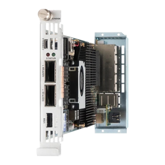
Keyer With Logo Insertion 2.5. REAR AND FRONT PANEL Error! Reference source not found. shows Rear and Front panesl of the 570DSK-12G-F modules. Figure 2-1: 570DSK-12G-F Rear and Front Panels 2.5.1. Front Panel Front panel is equipped with two QSFPs ports, one USB Type-A port and one USD Micro-B (5 pins) port. -
Page 15: Rear Panel
The rear plate is equipped with eight I/O SFP ports and two RJ-45 network connectors. The device supports both coaxial SFP3TR-HDBNC-12G SFP (Figure 2-2) and fiber SFP3TR–13–12G SFP – Evertz Ordering Numbers. A high quality coax cable should be used to help ensure optimum performance. -
Page 16: Source Videos
570DSK-12G-F Keyer With Logo Insertion 2.6. SOURCE VIDEOS 2.6.1. Video Inputs Video source connected to SFP1 is called Background video. This signal will be displayed through all the outputs ports, Program (odd output ports) and Preview (even output ports), – still when Keyer is disabled. -
Page 17: Connecting To An Ethernet Network
2.7. CONNECTING TO AN ETHERNET NETWORK The 570DSK-12G-F is designed to be used with either a 1Gbe or 10Gbe network, also known as Fast Ethernet, twisted pair Ethernet cabling systems. The cable must be “straight through” with a RJ-45 connector at each end. Create a network connection by plugging one end of the cable into the RJ-45 receptacle of the 570DSK and the other end into a port of the supporting network device. -
Page 18: Module Configuration
The 7700 upgrade cable, supplied with the 570FR/S570FR frame, is a multi-colored ribbon cable with a six pin header socket on one end and a female 9 pin D connector on the other end (Evertz part number WA-S76). This cable is normally in the vinyl pouch at the front of the manual binder. Connect the ribbon cable to port to J24 and power up the card. -
Page 19: Network Configuration
‘ifconfig eth0’ or ‘ifconfig eth1’. Figure 2-7: Tera Term – Network Configuration 2) To save the new IP address, login again with root/evertz and type ‘reboot’ as Figure 2-8. Figure 2-8: Tera Term – Saving New IP 2.9. -
Page 20: Figure 2-9: Command Prompt - Ftp To The Device
570DSK-12G-F Keyer With Logo Insertion Figure 2-9: Command Prompt – FTP to the Device 3) Press ‘Enter’ twice. Once the operation is done, type the following commands (Figure 2-10), in order access the local NAS, where the logos will be stored. -
Page 21: Logo Files
.json file (Java Script Object Notation) as well. 2.10.1. RGB File The 570DSK-12G-F supports 16-bit RGB. Moreover, no specific resolution is required for .rgb files, as long as the resolution is in accordance with the size and sharpness of the logo. -
Page 22: Figure 2-15: .Json File Data Content Of Static Logo
570DSK-12G-F Keyer With Logo Insertion The other information describe the structural data as it is bellow presented. Figure 2-15: .json File Data Content of Static Logo ID: This variable indicates the ID of the project NOTE: Different logos can have the same ID. -
Page 23: Figure 2-16: .Json File Data Content Of Animated Logo
570DSK-12G-F Keyer With Logo Insertion Figure 2-16: .json File Data Content of Animated Logo NOTE: The user must consider the offset_top and offset_left in relation to the desired video standard. As a result, the logo will be in a different location depending whether it is 3G or 12G video. -
Page 24: Figure 2-17: Output Video Signal With Zoomed Details Of The Activated Logo
570DSK-12G-F Keyer With Logo Insertion Figure 2-17: Output Video Signal with Zoomed Details of the Activated Logo Page 14... -
Page 25: Specification
570DSK-12G-F Keyer With Logo Insertion SPECIFICATION 3.1. CONFIGURATION Inputs Fixed at 8 ports (only 1-3 are functioning) Outputs Fixed at 8 ports Redundant Protection Redundant Power Supply 3.2. VIDEO INPUTS Standards SMPTE424M (3Gb/s) and SMPTE 2082 (12Gb/s) for video playload... - Page 26 570DSK-12G-F Keyer With Logo Insertion This page left intentionally blank Page 16...
-
Page 27: Web Interface
570DSK-12G-F can be completely configured using the web interface. 4.1. LOGIN The 570DSK-12G-F hosts its own web interface that can be accessed by using a web browser to navigate to the device’s IP address. The login username and password can be ‘customer/customer’, ‘root/evertz’ or ‘admin/admin’. -
Page 28: Firmware Upgrade
Figure 4-2: WebEASY – Side Menu ® 4.2. FIRMWARE UPGRADE Upgrading the 570DSK-12G-F is done using a button located on the top of the Web interface, labeled ‘Upgrade’. Figure 4-3: WebEASY – Top Menu ® The ‘Upgrade’ button is used to check current firmware version and to upload the latest firmware (Figure 4-4). -
Page 29: Figure 4-4: Webeasy - Firmware Upgrade
In case the firmware is outdated, the user can upload a new image by clicking ‘Choose File’ button and selecting the file name 570DSK-12G-F.tar.gz. Once the firmware is selected, click the ‘Upgrade’ button. The ‘Progress’ bar will show the status of the upload. -
Page 30: Device Status
570DSK-12G-F Keyer With Logo Insertion Once the device is done rebooting, login back into the web interface and verify if the firmware was correctly upgraded. In case the upgrade failed. Please, repeat the same steps described above. Otherwise, the user can begin configuring the web interface sections as outlined in the following chapters. -
Page 31: Licensing
570DSK-12G-F Keyer With Logo Insertion 4.3.3. Licensing Device UID: This parameter displays the devices unique ID, which it is required to request license(s) License Status: This parameter displays the license types (i.e.: ‘HD=Yes’ means that the device passes HD signals). -
Page 32: Media Config
The Media Config section allows the user to set the details of the FTP server – where the logos will be stored –, in order to connect it to the 570DSK-12G-F. See Section Error! Reference source not found. for details. -
Page 33: Ptp Control (Not Used, Future Use Only)
570DSK-12G-F Keyer With Logo Insertion 4.5. PTP CONTROL (NOT USED, FUTURE USE ONLY) Figure 4-8: WebEASY – PTP Control ® Page 23... -
Page 34: Sfp
570DSK-12G-F Keyer With Logo Insertion 4.6. Figure 4-9: WebEASY – SFP ® 4.6.1. SFP Status QSFP1-2: This section displays details of the QSFP plugged on ports 1-2 (future use) SFP1-8: This section displays details of the SFP plugged on ports 1-8 4.6.2. -
Page 35: Control Interfaces
570DSK-12G-F Keyer With Logo Insertion 4.7. CONTROL INTERFACES Figure 4-10: WebEASY – Control Interfaces ® 4.7.1. Port Configuration IP Address: This field set/displays the IP address to each Ethernet port Netmask: This field set/displays the Netmask address to each Ethernet port Reservation: This field is used to select a network protocol, whether it is ‘Static’... -
Page 36: Data Interface (Not Used, Future Use Only)
570DSK-12G-F Keyer With Logo Insertion 4.8. DATA INTERFACE (NOT USED, FUTURE USE ONLY) Figure 4-11: WebEASY – Data Interface ® 4.9. VIDEO INPUT Figure 4-12: WebEASY – Video Input ® 4.9.1. Input Configuration Program: This parameter indicates whether there is a valid input signal on SFP1 (‘Present’), or an invalid input video (‘Not Present’) -
Page 37: Video Output (Not Used, Future Use Only)
570DSK-12G-F Keyer With Logo Insertion 4.10. VIDEO OUTPUT (NOT USED, FUTURE USE ONLY) Figure 4-13: WebEASY – Video Output ® 4.11. AUDIO INPUT Figure 4-14: WebEASY – Audio Input ® 4.11.1. Input Audio Configuration Group 1-4: This section indicates whether there is valid input audio in each group of SFP1 (‘Present’) or an invalid input audio (‘Not Present’) -
Page 38: Output Audio Configuration
570DSK-12G-F Keyer With Logo Insertion 4.12.1. Output Audio Configuration Program: This section allows the user to select whether to “Enable’ or ‘Disable’ each group of audio through even output SFPs Preview: This section allows the user to select whether to “Enable’ or ‘Disable’ each group of audio... -
Page 39: Host Configuration And Ip Routes (Future Use Only)
570DSK-12G-F Keyer With Logo Insertion 4.15. HOST CONFIGURATION AND IP ROUTES (FUTURE USE ONLY) Figure 4-18: WebEASY – Host Configuration and IP Routes ® 4.16. GPIO CONFIG Figure 4-19: WebEASY – GPIO Config ® Page 29... -
Page 40: Control Panel Config
570DSK-12G-F Keyer With Logo Insertion 4.16.1. Control Panel Config This section allows the user to activate/deactivate the Keyer and logos. GPI Type: This field is used to select whether Keyer or logo will be displayed on the output signal ‘KeyerOnAir’: Activate Keyer •... -
Page 41: M2100 Remote Control
1) Open the AutomationLoader.exe Figure 5-1: M2100 – Automation Loader exe. file 2) Set the IP address of the 570DSK-12G-F, include the port (Default: 2100) and click ‘Open’ button to connect it to the device, as Figure 5-2. Page 31... -
Page 42: Figure 5-2: M2100 - Ip Configuration
570DSK-12G-F Keyer With Logo Insertion Figure 5-2: M2100 – IP Configuration Page 32... -
Page 43: Keyer
570DSK-12G-F Keyer With Logo Insertion 5.1. KEYER 5.1.1. Enable Keyer 1) Select ‘GVG_KEY_ENABLE’ in the ‘Command’ option, include ‘1’ in ‘Keyer’ and press ‘Add’ button, so the command will be moved/stored to the ‘Command List’ on the side of the window, as Figure 5-3. -
Page 44: Figure 5-4: M2100 - Activate Keyer Command
570DSK-12G-F Keyer With Logo Insertion 2) Select ‘GVG_KEY_ENABLE’ in the ‘Command List’ and press ‘Step’ button to activate the Keyer, as Figure 5-4. Figure 5-4: M2100 – Activate Keyer Command 3) The Keyer will be displayed through Preview (PVW) output signals – even SFP ports. -
Page 45: Figure 5-5: M2100 - Add Transition (From Pvw To Pgm) Command
570DSK-12G-F Keyer With Logo Insertion 4) In order to display the Keyer, also, through Program (PGM) output signals – odd SFP ports –, the ‘GVG_TX_START’ in ‘Command’ option must be selected. Type number ‘3’ in ‘Trigger’ and press ‘Add’ button, so the command will be moved/stored to the ‘Command List’ on the side of the window, as Figure 5-5. -
Page 46: Figure 5-6: M2100 - Activate Keyer Withtransition (From Pvw To Pgm) Command
‘Save’/’Save as’ option, which allows the user to activate the Keyer without adding a new command every time. NOTE: The 570DSK-12G-F will display the Keyer through the output signals only when all three input signals are connected (see Figure 1-1). Page 36... -
Page 47: Disable Keyer
570DSK-12G-F Keyer With Logo Insertion 5.1.2. Disable Keyer 1) In order to remove the Keyer only from PVW output signals, select ‘GVG_KEY_ENABLE’ again and press ‘Step’. The Keyer will remain only through PGM output signals (see step 2 of Section 5.1.1). -
Page 48: Figure 5-8: M2100 - Activate Command To Display Logo Through Pvw
570DSK-12G-F Keyer With Logo Insertion NOTE: The 570DSK-12G-F supports displaying more than one logo through the output signals. Therefore, the user can set the same command with different logo names in ‘Name’ field. 2) Select the ‘EVERTZ_MEDIA_CUE’ in the ‘Comand List’ and press ‘Step’ button to activate the logo, as Figure 5-8. -
Page 49: Enable Logos Through Pvw And, At The Same Time, Through Pgm Outputs
570DSK-12G-F Keyer With Logo Insertion 5.2.2. Enable Logos through PVW and, at the same time, through PGM outputs 1) Select ‘EVERTZ_MEDIA_IN’ in the ‘Command’ option, include the name of the logo in ‘Name’ field and press ‘Add’ button, so the command will be moved/stored to the ‘Command List’ on the side of the window, as Figure 5-9. -
Page 50: Figure 5-10: M2100 - Add Command To Display Logo Through All Outputs
The logo, in the WEB INTERFACE, will change from ‘Out’ to ‘logo_name: In’ NOTE: The 570DSK-12G-F supports displaying more than one logo through the output signals. Therefore, the user can set the same command with different logo names in ‘Name’ field. -
Page 51: Disable The Logos Displayed Through Pvw
570DSK-12G-F Keyer With Logo Insertion 5.2.3. Disable the Logos displayed through PVW 1) In order to remove the logo from PVW output signals (before using ‘GVG_TX_START’), select ‘EVERTZ_MEDIA_OUT’ in the "Command" option, include the name of the logo in ‘Name’ field and press "Add"... - Page 52 5) In case ‘GVG_TX_START’ is used a third time, the logo will be removed from PGM and it will be displayed once again through PVW. NOTE: The 570DSK-12G-F supports displaying/removing more than one logo through the output signals. Therefore, the user can set the same command with different logo names in ‘Name’ field.
-
Page 53: Definitions
570DSK-12G-F Keyer With Logo Insertion DEFINITIONS 4:2:2: The sampling ration used in the HDTV digital video signal. For every 4 samples of luminance, there are 2 samples each of R-Y (red minus luminance) and B-Y (blue minus luminance). 16x9: A wide-screen television format such as HDTV in which the aspect ratio of the screen is 16 units wide by 9 units high as opposed to the 4x3 aspect ratio of traditional SD television. - Page 54 570DSK-12G-F Keyer With Logo Insertion DROP FRAME: In NTSC systems, where the frame rate is 29.97002618 frames per second, the drop frame mode permits time of day indexing of the frame numbers by dropping certain frame numbers. Specifically frames 0, and...
- Page 55 570DSK-12G-F Keyer With Logo Insertion SMPTE 125M: The SMPTE standard for bit parallel digital interface for component video signals. SMPTE 125M defines the parameters required to generate and distribute component video signals on a parallel interface. SMPTE 259M-C: The SMPTE standard for 525- and 625-line serial digital component and composite interfaces.
- Page 56 570DSK-12G-F Keyer With Logo Insertion End of Document Page 46...
Need help?
Do you have a question about the 570DSK-12G-F and is the answer not in the manual?
Questions and answers