Table of Contents
Troubleshooting

Subscribe to Our Youtube Channel
Related Manuals for StepperOnline RS485


Summary of Contents for StepperOnline RS485
- Page 1 User Manual Modbus RS485 Stepper Drive ©2022 All Rights Reserved Address:15-4, #799 Hushan Road, Jiangning, Nanjing, China Tel: 0086-2587156578 Web: www.omc-STEPPERONLINE.com Sales:sales@STEPPERONLINE.com Support: technical@STEPPERONLINE.com...
- Page 2 Strictly adhere to the technical information regarding installation requirements. This manual is not for use or disclosure outside of STEPPERONLINE except under permission. All rights are reserved. No part of this manual shall be reproduced, stored in retrieval form, or transmitted by any means, electronic, mechanical, photocopying, recording, or otherwise without approval from STEPPERONLINE.
- Page 3 Modbus RS485 Stepper Drive User Manual Safety Precautions Overall Notes Do not remove the housing with the drive powered on. Cables. Connectors and optional equipment. Please disconnect the power supply for at least 2 minutes and make sure ...
- Page 4 Modbus RS485 Stepper Drive User Manual Precautions for Installation Please install the drive in a cabinet that provides fire protection. Electrical protection in the control cabinet. Please install the driver and motor in a position with sufficient weight ...
-
Page 5: Table Of Contents
3.2 Wiring Instructions .......................... 7 3.2.1 Power Supply Cable & Motor Cable ..................8 3.2.2 I/O Signal Cable ........................8 3.2.3 RS485 Communication Cable ..................... 8 3.3 Interface Specifications ........................8 3.3.1 Connectors Definition ......................8 3.3.2 CN1 &CN2 Input Power Connector ..................9 3.3.3 CN3-I/O Signals Connector .................... - Page 6 4 Modbus RTU ............................14 4.1 Communication Specifications ..................... 14 4.2 Modbus Function Codes (FC) ...................... 14 4.2.1 Read Holding Registers FC= 03 ..................15 4.2.2 Preset Single Register FC= 06 ..................16 4.2.3 Preset Multiple Registers FC= 10 ..................17 4.3 Modbus & PR Parameters ......................18 4.3.1 Basic Parameters .......................18 4.3.2 Input and Output Parameters ....................
- Page 7 6.1 Basic operation of STEPPERONLINE MotionStudio ..............44 6.1.1 Preparation and Steps ....................... 44 6.1.2 Operation of Trial Run ......................46 6.1.3 Operation of PR Function ....................47 6.2 Basic Operation of Serial Port Tools Software ................49 6.2.1 Preparation and Steps ....................... 49 6.2.2 Operation Instruction Format .....................
-
Page 8: Introduction
1 Introduction 1.1 Product Introduction DMRS Series are stepper drive based on standard Modbus RTU protocol, using RS485 communication can network up to 31 axes. They built-in PR feature with 16-segment position table (PR Mode) can save additional controllers in most of point-to-point applications, to greatly enhance system reliability and reduce the cost. DMRS Series also support the feature of teaching, the operation modes of Profile Position, Profile Velocity and Homing. - Page 9 Modbus RS485 Stepper Drive User Manual can write more complex programs to let motion more intelligent, and the HMI can monitor and modify the drive parameters in real time. (2) Controlled by I/O (switch signal or PLC) The user only needs to turn off the switch signal to realize the PR motion, which is simple to control and low-cost design.
-
Page 10: Check Of Product
Modbus RS485 Stepper Drive User Manual 1.4 Check of Product 1.4.1 Arrival inspection Check whether the surface of the product is damaged or not during transportation. Check the nameplate models of the drive and motor are what you have ordered. -
Page 11: Parts Description
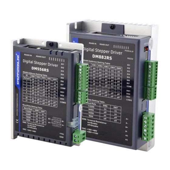
Modbus RS485 Stepper Drive User Manual 1.4.4 Parts description 1.4.5 Accessories Information Name Necessary Picture Description Need to cost extra Tuning CABLE-PC-1 cable Cable (CABLE-TX*M*-BUS) Optional length: 0.1m, Network 0.2m, 0.3m, 0.4m, cable 1m, 1.5m, 2m, 3m,5m,7m, 10m,15m, Note: (1) Tuning cable is not necessary, but it is recommended to order. -
Page 12: Dimensions
Modbus RS485 Stepper Drive User Manual DO NOT mount the drive and motor in a location subjected to corrosive or flammable gases, and combustibles. Please mount the drive and motor in an indoor electric control cabinet without liquid where direct sunlight is avoided. -
Page 13: Product Specifications
Modbus RS485 Stepper Drive User Manual Figure 2.2: DMRS series installation drawing 3 Product Specifications Don’t hot plug the motor wiring, encoder wiring and RS232 communication wiring during power on. Be sure to check the connections and make sure the power lead polarity is correct, ... -
Page 14: Wiring Instructions
Figure 3.1 Wiring Instructions Note: (1) There are two RS485 communication ports above, one of them is input port which connects with master station or previous slave, and the other is output port which connects with the following slave. (2) Single-ended inputs I1, I2, I3, I4, I5, I6 and I7 connection types can be common-cathode and common-anode. -
Page 15: Power Supply Cable & Motor Cable
Modbus RS485 Stepper Drive User Manual 3.2.1 Power Supply Cable & Motor Cable Wire diameter: +VDC, GND, A+, A-, B+, B- terminal wire diameter≥0.3mm (AWG15-22) A noise filter which can improve anti-interference performance is recommended to be connected between power ... -
Page 16: Cn1 &Cn2 Input Power Connector
Modbus RS485 Stepper Drive User Manual 3.3.2 CN1 &CN2 Input Power Connector DM556RS Name Signal Description 24V- 48V Motor phase A+ Motor phase B+ Motor phase A- Motor phase B- DM882RS Name Signal Description Motor phase A+ Motor phase B+ Motor phase A- CN1&CN2... -
Page 17: Cn4-Rs485 Communication Connector
Modbus RS485 Stepper Drive User Manual Note:(1) DI1 is normally closed, default by Enable signal. It means the motor is locked shaft after the driver powered (2) When using Brake output signals, you need to connect a relay and a diode 3.3.4 CN4-RS485 Communication Connector... - Page 18 Modbus RS485 Stepper Drive User Manual Note: (1) When the SW1-SW5 is default (all are on), the Slave ID can be configured by the PC software (2) Baud Rate: SW6 - SW7 Baud Rate 115200 (Default) 38400 (Factory) 19200 9600...
-
Page 19: I/O Connection
3.4.3 Brake Output Use PC software (from STEPPERONLINE or Controller or PLC vendor) to configure this output as a BRAKE CONTROL output. In this case, this signal can be used for automatic brake control while system power failure. It is recommended to connect a fly-wheel diode in parallel to a 24VDC relay and brake coil connection. - Page 20 Modbus RS485 Stepper Drive User Manual Figure 3.5: Brake output connection...
-
Page 21: Modbus Rtu
Write value to multiple data Check Mode CRC-16 Left is Low-bit, Right is high-bit Message Length Variable, the max length is 200byte Single message communication rate of RS485: (Unit: ms) Time from transmission Baud Start receiving to send Receive wait completion to recovery of... -
Page 22: Read Holding Registers Fc= 03
Modbus RS485 Stepper Drive User Manual 4.2.1 Read Holding Registers FC= 03 Read Holding Registers Query (Master to Read Holding Registers Response (Slave to Master) Slave) Slave ID 00 - 1F Slaver ID 00 - 1F High High Address of beginning... -
Page 23: Preset Single Register Fc= 06
Modbus RS485 Stepper Drive User Manual Note: (1) The above example shows reading the value of Pr5.22, Pr5.23, Pr5.24, their corresponding address are 0x01BD, 0x01BF, 0x01C1. (2) The data type of parameter is 32bit ,which include high 16bit register and low 16bit register. Usually, we use low 16bits only, but it needs to take the high 16 bits as beginning when we read/write multiple parameters continuously. -
Page 24: Preset Multiple Registers Fc= 10
Modbus RS485 Stepper Drive User Manual Message: 18 01 22 11 06 06 Description Address Function code Register address Write data CRC check code Slave>master data: Message: 18 01 22 11 06 06 Description Address Function code Register address Write data CRC check code Note: 0x1801-- Auxiliary control word, and 0x2211 is to save the value to EEPROM. -
Page 25: Modbus & Pr Parameters
4.3.1 Basic Parameters STEPPERONLINE RS485 parameter data type is 32 bits, a parameter contains two registers of high 16 bits and low 16 bits, only the lower 16 bits are used in practice. However, when reading or writing multiple parameters in succession, the high 16 bits of the parameter need to be used as the start, usually 00. - Page 26 Modbus RS485 Stepper Drive User Manual bit4: Locked shaft alarm bit5: EEPROM alarm bit6: Auto-tuning alarm 0x0177 Pr4.27 Bus voltage 0-65535 0.1V 0x0179 Pr4.28 Digital input statue Bit0-Bit6: DI1-DI7 0-65535 0x017B Pr4.29 Digital output statue Bit0-Bit2: DO1-DO3 0-65535 0x0187 Pr4.35...
-
Page 27: Input And Output Parameters
Modbus RS485 Stepper Drive User Manual completed Write Function value 0x1111 Reset current alarm 0x1122 Reset history alarm Save all parameters to 0x2211 EEPROM Parameter reset(exclude 0x2222 0x1801 Control word motor parameters) All parameters are reset 0x2233 to factory Save all mappings into... -
Page 28: Smooth Filter Time Setting For Digital Inputs
Modbus RS485 Stepper Drive User Manual Digital Input port function assignment: Normal-open (N.O); Normal-closed (N.C). Digital Inputs Digital Outputs Type Type Functions Symbols Functions Symbols N.O. N.C. N.O. N.C. Command Trigger Command CTRG 0x20 0xA0 CMD_OK 0x20 0xA0 Complete Homing Trigger... -
Page 29: Status Monitoring Parameters
Modbus RS485 Stepper Drive User Manual Reserved Filter time setting Bit15 Bit14 Bit13 Bit12 Bit11 Bit10 Bit9 Bit8 Register Filtering time (unit: ms) Value 0000 0001 0010 0011 0100 0101 0110 0111 1000 1001 Reserved bit, write 0 by default... -
Page 30: Control Word And Status Word
Modbus RS485 Stepper Drive User Manual 0x1013 (low 16-bit) 0x1014 (high 16-bit) Feedback position pluses 0x1015 (low 16-bit) 0x1044 (high 16-bit) Profile velocity 0x1045 (low 16-bit) 0x1046 (high 16-bit) Feedback velocity 0x1047 (low 16-bit) 4.3.5 Control Word and Status Word (1) The related function is started by sending the control word, (2) The completion is judged by checking the status word. -
Page 31: Drive Alarm Codes And Troubleshooting
Modbus RS485 Stepper Drive User Manual Error Code Error Code (EC) Description 0x01 Wrong FC (This supports FC beside of 03h/ 06h/ 10h) 0x02 Wrong access address 0x03 Wrong data, for example, write data over-limit value, etc. 0x08 Wrong CRC check code Example F: CRC check code error Master->... -
Page 32: Error Clear
STEPPERONLINE MotionStudio, and the second is via external I/O,refer to Section 4.3.2. (3) If the current error cannot be cleared, please check the drive All history error records can be cleared by STEPPERONLINE Clear history error History error MotionStudio 4.5 Register Mapping Continuous Read/Write Function Address description 0x0F10-0x0F19. - Page 33 Modbus RS485 Stepper Drive User Manual Examples Mapping target Write to Parameter original address address 0x0F10 ← 0x0001 (Pr0.00: Microstep) 0x0F11 ← 0x0009 (Pr0.04: inductance value) 0x0F12 ← 0x00A1 (Pr2.00: instruction filter time) 0x0F13 ← 0x0191 (Pr5.00: peak current) 0x0F14 ←...
-
Page 34: S-Code Application
Modbus RS485 Stepper Drive User Manual (2) Read and write Master→Slave: 01 03 0F 00 00 0A C6 D9 Slave → Master: 01 03 14 27 10 05 87 00 0F 00 3C 00 FA 00 03 0F A0 00 5A 00 01 00 00 00 56 F4 (3) Mapping parameter save instruction 0x2244 Master→Slave:... -
Page 35: Enable Drive
DI1 of DMRS series drive is the enable input by default, normally closed, so DMRS drive immediately enters the enable state after power on. RS485 communication: Pr0.07 of STEPPERONLINE MotionStudio (Register address 0x00F) set to value “1” indicates enable the drive by RS485... -
Page 36: Pr Mode (Indexer Table)
Move to the specified position after homing; Acc/Dec of homing velocity can be set; Note: Control instruction can not be sent to drive during homing JOG can be realized by external I/O or RS485 communication. CW JOG; CCW JOG; ... -
Page 37: Homing Parameters
Automatic homing on power-up: After the drive is powered on, the motor will automatically search the zero position. Trigger to homing: when IO port set to Home function triggered by external level, or trigger via Modbus RS485. Homing method: Limit switch homing: Set by register address 0x600A, or STEPPERONLINE software. -
Page 38: Homing By Home Switch
Modbus RS485 Stepper Drive User Manual Register Parameters Definition Description address Bit0: homing direction =0:CCW; =1:CW. Bit1: move to the Specified point after homing? =0: No; =1: Yes. Bit2: homing type Pr8.10 0x600A Homing mode =0: Homing by detecting limit switch signal... - Page 39 Modbus RS485 Stepper Drive User Manual (1) Home Switch & Positive Limit Switch (2) Home Switch at Positive Direction (3) Home Switch & Negative Limit Switch...
-
Page 40: Homing By Limit Switch
Modbus RS485 Stepper Drive User Manual (4) Home Switch at Negative Direction 5.2.3. Homing by Limit Switch (1) Positive Limit Switch (2) Negative Limit Switch... -
Page 41: Soft Limit & Jog & Quick Stop
Modbus RS485 Stepper Drive User Manual 5.3 Soft Limit & JOG & Quick Stop 5.3.1 Soft Limit The soft limit function means that the internal position feedback of the drive is compared with the limit position, an alarm and stop when determining that the motor exceeds the limit position. Soft limit function is universal for linear movement and rotating movement.It is not requiring hardware, eliminating malfunction due to poor wiring contact,... - Page 42 Note:(1) Pr8.39 - Pr8.41(JOG) are available when triggered by I/O; (2) Pr6.00 - Pr6.03 (JOG) are available when triggered by RS485. The trigger mode of JOG is divided into two types: RS485 communication and IO, which correspond to different parameter addresses: RS485 communication trigger JOG: Write value 0x4001 to 0x1801, JOG+.
-
Page 43: Quick Stop
5.4.1 PR Parameters Usually it is recommended using the PTP window of the STEPPERONLINE tuning software to configure the PR path parameters, but it can also use the following objects: Par. # in software... -
Page 44: Pr Path Configuration
Modbus RS485 Stepper Drive User Manual Pr9.02 0x6202 Position L Low 16 bit Pr9.03 0x6203 velocity Unit: rpm Pr9.04 0x6204 Unit: ms/1000rpm Pr9.05 0x6205 Unit: ms/1000rpm Pr9.06 0x6206 Pause time Pause time after the command is stopped PR Path 0 maps directly to Pr8.02, Others are Pr9.07... -
Page 45: Other Functions Of Pr
Modbus RS485 Stepper Drive User Manual Path 10 Path 11 Path 12 Path 13 Path 14 Path 15 Note: The 4 digital inputs do not have to be configured as ADD0 - ADD3, it is configured according to the actual required path motions. - Page 46 Modbus RS485 Stepper Drive User Manual Multi-segment jump path sequence diagram Continuous movement The bit5 of Pr9.00 is 0 , which does not overlap the continuous path. As shown in the figure below, set PR1 (PR path1) and PR2 (PR path2) to run continuously and PR1 jump. There is no in-position signal in the intermediate delay from PR1 jump to PR2.
-
Page 47: Trigger Methods
Modbus RS485 Stepper Drive User Manual Interrupt function timing sequence 5.5 Trigger Methods 5.5.1 CTRG Trigger When the path triggered by CTRG, it can be configured for rising edge triggering or double edge triggering. (No falling edge trigger function). Par. #... -
Page 48: Io Combination Trigger
Modbus RS485 Stepper Drive User Manual When CTRG is on, SI1 and SI2 are off, the path 0 is triggered; When CTRG and SI1are on, and SI2 is off, the path 1 is triggered; When CTRG and SI2 are on, and SI1 is off, the path 2 is triggered;... -
Page 49: Immediate Trigger
Modbus RS485 Stepper Drive User Manual 1. Firstly, configure required homing and path, it can be set through controller/PLC software after power-on , or through STEPPERONLINE PC software; 2. Enable drive; 3. Write corresponding command to the 0x6002 to realize the selection and startup of each action. - Page 50 Modbus RS485 Stepper Drive User Manual 10-11 Pr9.01 High position XXXX 12-13 Pr9.02 Low position XXXX 14-15 Pr9.03 velocity XXXX 16-17 Pr9.04 Acceleration XXXX 18-19 Pr9.05 Deceleration XXXX Pr9.06 20-21 Delay time XXXX Pr9.07 22-23 Trigger control 0x0010 Check code...
-
Page 51: Tuning Operations
CABLE-PC-1 Pin Definition It is recommended that users order this cable directly from STEPPERONLINE, not to make it yourself (2) USB to RS232 converter, sometimes it needs to manually install the drive program. (3) COM port selection, as shown in the figure below, the communication port is COM3: (4) Connect tuning software Select COM3, do not select baud rate and device number, keep the default settings. - Page 52 Modbus RS485 Stepper Drive User Manual (5) Basic parameter setting (6) Input and output function and polarity setting...
-
Page 53: Operation Of Trial Run
Modbus RS485 Stepper Drive User Manual Note: After setting the parameters, click "OK". Then, in the parameter management window, click the Save button to prevent the parameter values from being lost after the drive is powered off. 6.1.2 Operation of Trial Run... -
Page 54: Operation Of Pr Function
Modbus RS485 Stepper Drive User Manual 6.1.3 Operation of PR Function (1) This window can set the CTGR trigger and Homing parameters of PR motion: (2) This window is the PR path parameter setting, including operation mode, target position, speed value, etc. - Page 55 Modbus RS485 Stepper Drive User Manual After the setting is completed, please click to download and save, as follows (3) Manually run the PR path As shown in the figure below, the default is the motion parameter of PR0. As long as click Start, the motor will run according to the path of PR0.
-
Page 56: Basic Operation Of Serial Port Tools Software
Modbus RS485 Stepper Drive User Manual 6.2 Basic Operation of Serial Port Tools Software This is to control the motor through RS485 communication, user can realize the movement of the motor by sending commands to the corresponding registers. 6.2.1 Preparation and Steps... -
Page 57: Operation Instruction Format
Modbus RS485 Stepper Drive User Manual (2) COM port selection, as shown in the figure below, the communication port is COM3: (4) Connect tuning software Select COM3, select the same baud rate as the drive settings. After clicking connect. 6.2.2 Operation Instruction Format... - Page 58 Modbus RS485 Stepper Drive User Manual 01 06 62 03 02 58 66 E8 Set PR0 speed value 01 06 62 04 00 32 56 66 Set PR0 acceleration 01 06 62 05 00 32 07 A6 Set PR0 deceleration velocity...
-
Page 59: Appendix A Parameters List
1. Modbus RTU Parameters The STEPPERONLINE RS485 parameter data type is 32-bit data, and a parameter contains two registers, high 16 bits and low 16 bits, but in practice most parameters only need to use the low 16 bits. When reading and writing multiple parameters in succession, the high 16 bits of the parameter need to be used as the start. - Page 60 Modbus RS485 Stepper Drive User Manual Percentage of shaft locked 0x0197 Pr5.03 0-100 Keep default normally current(power on) 0x0199 Pr5.04 0-1500 Shaft locked duration Keep default normally Rising time of shaft locked 0x019F Pr5.07 1-60 100ms Keep default normally current (power on) 0x01A5 Pr5.10...
- Page 61 Modbus RS485 Stepper Drive User Manual Read only Error code Means 0x01 Over- current 0x02 Over- voltage 0x40 Current sampling fault 0x2203 Current alarm 0x80 Failed to lock shaft 0x200 EEPROM fault 0x100 Auto-tuning fault 2. PR Parameters: PR parameter data type is 16-bit data, one parameter occupies one register (one 16-bit register = 2 8-bit bytes).
- Page 62 Modbus RS485 Stepper Drive User Manual Pr8.40 0x6028 Unit: ms/1000rpm JOG Acceleration Pr8.41 0x6029 Unit: ms/1000rpm JOG Deceleration , it Read only. High 16-bit (0-65535) will be cleared after successful Profile position H Pr8.42 0x602A homing , it Read only. Low 16-bit (0-65535)
- Page 63 Modbus RS485 Stepper Drive User Manual Pr9.13 0x620D Pr9.14 0x620E Pause time Pr9.15 0x620F Special parameter Pr9.16 0x6210 Motion of Path 2 Pr9.17 0x6211 Position H Pr9.18 0x6212 Position L Pr9.19 0x6213 velocity Pr9.20 0x6214 Pr9.21 0x6215 Pr9.22 0x6216 Pause time Pr9.23...
Need help?
Do you have a question about the RS485 and is the answer not in the manual?
Questions and answers