
Subscribe to Our Youtube Channel
Related Manuals for StepperOnline DM556T


Summary of Contents for StepperOnline DM556T
- Page 1 User’s Manual DM556T 2-Phase Digital Stepper Drive Version 1.0 Designed by StepperOnline® ©2017 All Rights Reserved Web site: www.omc-stepperonline.com E-Mail: sales@stepperonline.com...
- Page 2 Strictly adhere to the technical information regarding installation requirements. This manual is not for use or disclosure outside of STEPPERONLINE except under permission. All rights are reserved. No part of this manual shall be reproduced, stored in retrieval form, or transmitted by any means, electronic, mechanical, photocopying, recording, or otherwise without approval from STEPPERONLINE.
-
Page 3: Table Of Contents
DM556T Digital Stepper Drive User Manual Table of Contents 1. Introductions ................................. 2 1.1 Features ................................2 1.2 Applications ................................. 2 2. Specifications ................................2 2.1 Electrical Specifications............................2 2.2 Environment ................................ 2 2.3 Mechanical Specifications ............................ 3 2.4 Elimination of Heat .............................. 3 3. -
Page 4: Introductions
1.2 Applications The DM556T stepper drive are designed to power 2 phase (1.8°) or 4-phase (0.9°) NEMA 23, 24, and 34 hybrid stepper motors. It can be easily adopted in many industries (CNC, medical, automation, packaging…), such as X-Y tables, engraving machines, labeling machines, mills, plasma, laser cutters, pick and place devices, and so on. -
Page 5: Mechanical Specifications
* Side mounting recommended for better heat dissipation 2.4 Elimination of Heat DM556T reliable working temperature should be < 60℃ (140°F) It is recommended to use automatic idle-current mode to reduce motor heating. That means set the SW4 pin of DIP switch at “OFF”... -
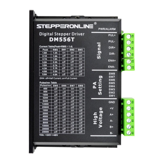
Page 6: Connection Pin Assignments And Led Indication
3. Connection Pin Assignments and LED Indication The DM556T has two connector blocks P1&P2 (see above picture). P1 is for control signals connections, and P2 is for power and motor connections. The following tables are brief descriptions of the two connectors. More detailed descriptions of the pins and related issues are presented in section 4, 5, 9. -
Page 7: Led Light Indication
3.3 LED Light Indication There are two LED lights for DM556T. The GREEN one is the power indicator which will be always on generally. The RED one is a protection indicator which will flash 1-2 times in a 3-second period, when protection enabled for a DM556T. -
Page 8: Half Coil Configuration
DM556T Digital Stepper Drive User Manual 5.2.1 Half Coil Configuration As previously stated, the half coil configuration uses 50% of the motor phase windings. This gives lower inductance, hence, lower torque output. Like the parallel connection of 8 lead motor, the torque output will be more stable at higher speeds. -
Page 9: Parallel Connection
6.2 Power Supply Sharing Multiple DM556T drives can share one power supply to reduce cost, if that power supply has enough power capacity. To avoid cross interference, connect each stepper drive directly to the shared power supply separately. To avoid cross interference, DO NOT daisy-chain connect the power supply input pins of the Drivers. -
Page 10: Dip Switch Configurations
DM556T Digital Stepper Drive User Manual of +24 - +48 VDC, leaving room for power line voltage fluctuation and back-EMF. Higher supply voltage can increase motor torque at higher speeds, thus helpful for avoiding losing steps. However, higher voltage may cause bigger motor vibration at lower speed, and it may also cause over-voltage protection or even drive damage. -
Page 11: Dynamic Current Configurations
The current automatically reduced to 50% of the selected dynamic current 0.4 second after the last pulse. 7.3 Automatic Motor Matching & Self Configuration When powered on a DM556T will automatically configure itself with the best settings to match the driven stepper motor for optimal performance. No action is needed. -
Page 12: Sequence Chart Of Control Signals
DM556T Digital Stepper Drive User Manual generator). A typical connection is shown as figure 9. Figure 9: Typical connection 10. Sequence Chart of Control Signals In order to avoid some fault operations and deviations, PUL, DIR and ENA should abide by some rules, shown as... -
Page 13: Protection Functions
DM556T Digital Stepper Drive User Manual 11. Protection Functions To improve reliability, the drive incorporates some built-in protections features. Time(s) of Priority Sequence wave of red LED Description Blink Over-current protection activated when peak current exceeds the limit. Over-voltage protection activated when drive working voltage is greater than 60VDC Reserved. -
Page 14: Warranty
OMC Co., Ltd. warrants its products against defects in materials and workmanship for a period of 12 months from shipment out of factory. During the warranty period, STEPPERONLINE will either, at its option, repair or replace products which proved to be defective.
Need help?
Do you have a question about the DM556T and is the answer not in the manual?
Questions and answers