
Subscribe to Our Youtube Channel
Related Manuals for StepperOnline CL57T


Summary of Contents for StepperOnline CL57T
- Page 1 User Manual CL57T(V3.0) Closed Loop Stepper Driver Revision 3.0 #7 Zhongke Road, Jiangning, Nanjing, China T: 0086-2587156578 ©2017 All Rights Reserved Web site: www.omc-stepperonline.com E-Mail:sales@stepperonline.com...
- Page 2 Strictly adhere to the technical information regarding installation requirements. This manual is not for use or disclosure outsides of STEPPERONLINE except under permission. All rights are reserved. No part of this manual shall be reproduced, stored in retrieval form, or transmitted by any means, electronic, mechanical, photocopying, recording, or otherwise without approval from STEPPERONLINE.
-
Page 3: Table Of Contents
CL57T(V3.0) Closed-loop Stepper Driver Table of Contents 1. Introductions................................1 1.1 Features................................1 1.2 Applications................................1 2. Specifications................................1 2.1 Electrical Specifications............................. 1 2.2 Environment................................. 1 2.3 Mechanical Specifications..........................2 2.4 Elimination of Heat..............................2 3. Connection Interface and LED Indication......................2 3.1 Connector P1 Interface............................3 3.1.1 Pin Assignments of P1..........................3... -
Page 4: Introductions
Protections for over-voltage, over-current and position following error 1.2 Applications Its great features of quicker response and no hunting make STEPPERONLINE’s closed loop stepper driver is ideal for applications such as bonding and vision systems in which rapid motions with a short distance are required and hunting would be a problem. -
Page 5: Mechanical Specifications
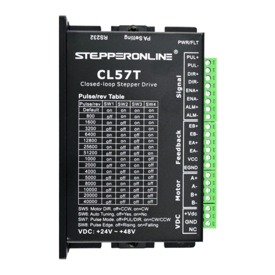
3. Connection Interface and LED Indication The CL57T has four connector blocks P1&P2&P3&P4 (see above picture). P1 is for control signals connections, P2 is for power and motor connections, P3 is for encoder signals input connections, and P4 is for connecting with PC tuning software. -
Page 6: Connector P1 Interface
The CL57T can accept differential and single-ended inputs (including open-collector and PNP output). The CL57T has 3 optically isolated logic inputs which are located on connector P1 to accept line drive control signals. These inputs are isolated to minimize or eliminate electrical noises coupled with the drive control signals. -
Page 7: Connector P2
CL57T is powered on. 3.2.2 Motor and Power Supply Wiring(P2) The CL57T can drive NEMA17, 23 and 24 closed loop stepper motor with encoder resolution of 1000 ppr. The current loop PID will be adjusted automatically regarding to function of motor auto-identification and parameter auto-configuration, to output optimal torque from wide-range motors. -
Page 8: Connector P3
3.5 LED Light Indication There are two LED lights for CL57T. The GREEN one is the power indicator which will be always on generally. The RED one is a protection indicator which will flash 1,2 or 7 times in a 5-second period, when protection enabled for a CL57T. -
Page 9: Selecting Supply Voltage
4A rating. 4.2 Power Supply Sharing Multiple CL57T drivers can share one power supply to reduce cost, if that power supply has enough power capacity. To avoid cross interference, connect each stepper drive directly to the shared power supply separately. -
Page 10: Other Dip Switch Setting(Sw5-Sw8)
CL57T(V3.0) Closed-loop Stepper Driver 2000 4000 5000 8000 10000 20000 40000 5.2 Other DIP Switch Setting(SW5-SW8) Function Default Direction CW (clock-wise) CCW (counter-clock-wise) Auto Tuning Pulse Model CW/CCW(double pulse) PUL/DIR(single pulse) Pulse Edge Falling Rising Notes: (1) The factory setting of DIP switch are ‘on off on on off off off off’;... -
Page 11: Sequence Chart Of Control Signals
CL57T(V3.0) Closed-loop Stepper Driver 7. Sequence Chart of Control Signals In order to avoid some fault operations and deviations, PUL, DIR and ENA should abide by some rules, shown as following diagram: Figure 5: Sequence chart of control signals Remark: 5s... -
Page 12: Protection And Troubleshooting
CL57T(V3.0) Closed-loop Stepper Driver 8. Protection and Troubleshooting To improve reliability, the drive incorporates some built-in protections features. Blink Sequence wave of red LED Description Trouble shooting time(s) Turn off the power immediately. 0.2S Over-current a) Check wiring is short-circuited or not;... -
Page 13: Warranty
CL57T(V3.0) Closed-loop Stepper Driver 9. Warranty STEPPERONLINE warrants its products against defects in materials and workmanship for a period of 12 months from shipment. During the warranty period, STEPPERONLINE will either, at its option, repair or replace products which proved to be defective. To obtain warranty service, a returned material authorization number (RMA) must be obtained before returning product for service.
Need help?
Do you have a question about the CL57T and is the answer not in the manual?
Questions and answers