
Related Manuals for StepperOnline DM860I


Summary of Contents for StepperOnline DM860I
- Page 1 User’s Manual DM860I Fully Digital Stepper Drive Version 1.0 Designed by StepperOnline® ©2017 All Rights Reserved Web site: www.omc-stepperonline.com E-Mail: sales@stepperonline.com...
-
Page 2: Table Of Contents
DM860I Full Digital Stepper Drive Manual Table of Contents 1. Introduction, Features and Applications........................1 Introduction................................. 1 Features..................................1 Applications.................................1 2. Specifications................................1 Electrical Specifications (T = 25℃/77℉)......................... 1 Operating Environment and other Specifications....................... 2 Mechanical Specifications (unit: mm [1inch=25.4mm]).................... 2 Elimination of Heat..............................2 3. -
Page 3: Introduction, Features And Applications
1. Introduction, Features and Applications Introduction The DM860I is a fully digital stepper drive developed with advanced DSP control algorithm based on the latest motion control technology. It has achieved a unique level of system smoothness, providing optimal torque and nulls mid-range instability. -
Page 4: Operating Environment And Other Specifications
DM860I Full Digital Stepper Drive Manual Operating Environment and other Specifications Cooling Natural Cooling or Forced cooling Environment Avoid dust, oil fog and corrosive gases 0℃ - 65℃ Ambient Temperature 40%RH - 90%RH Operating Environment Humidity -10℃ - 45℃ Operating Temperature 10-55Hz/0.15mm... -
Page 5: Pin Assignment And Description
3. Pin Assignment and Description The DM860I has two connectors, connector P1 for control signals connections, and connector P2 for power and motor connections. The following tables are brief descriptions of the two connectors. More detailed descriptions of the pins and related issues are presented in section 4, 5, 9. -
Page 6: Control Signal Connector (P1) Interface
4. Control Signal Connector (P1) Interface The DM860I can accept differential and single-ended inputs (including open-collector and PNP output). The DM860I has 3 optically isolated logic inputs which are located on connector P1 to accept line drive control signals. These inputs are isolated to minimize or eliminate electrical noises coupled onto the drive control signals. -
Page 7: Full Coil Configurations
DM860I Full Digital Stepper Drive Manual Figure 6: 6-lead motor half coil (higher speed) connections Full Coil Configurations The full coil configuration on a six lead motor should be used in applications where higher torque at lower speeds is desired. This configuration is also referred to as full copper. In full coil mode, the motors should be run at only 70% of their rated current to prevent over heating. -
Page 8: Power Supply Selection
DM860I Full Digital Stepper Drive Manual 6. Power Supply Selection The DM860I can match medium and small size stepping motors (frame size from NEMA24 to 34) made by STEPPERONLINE or other motor manufactures around the world. To achieve good driving performances, it is important to select supply voltage and output current properly. -
Page 9: Current Settings
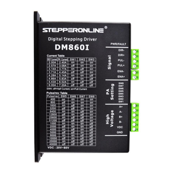
DM860I Full Digital Stepper Drive Manual Microstep Steps/rev.(for 1.8° motor) 1600 3200 6400 12800 25600 51200 1000 2000 4000 5000 8000 10000 20000 40000 Current Settings For a given motor, higher drive current will make the motor to output more torque, but at the same time causes more heating in the motor and drive. -
Page 10: Standstill Current Setting
ON meaning that standstill current is set to be the same as the selected dynamic current. The current automatically reduced to 50% of the selected dynamic current one second after the last pulse. If the application needs a different standstill current, please contact STEPPERONLINE. Motor auto-identification and parameter auto-configuration... -
Page 11: Protection Functions
DM860I Full Digital Stepper Drive Manual following diagram: Figure 11: Sequence chart of control signals Remark : a)t1: ENA must be ahead of DIR by at least 5s. Usually, ENA+ and ENA- are NC (not connected). See “Connector P1 Configurations” for more information. -
Page 12: Frequently Asked Questions
DM860I Full Digital Stepper Drive Manual 12. Frequently Asked Questions In the event that your drive doesn’t operate properly, the first step is to identify whether the problem is electrical or mechanical in nature. The next step is to isolate the system component that is causing the problem. As part of this process you may have to disconnect the individual components that make up your system and verify that they operate independently.
Need help?
Do you have a question about the DM860I and is the answer not in the manual?
Questions and answers