Advertisement
Quick Links
User Manual
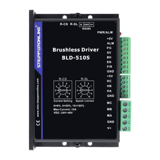
BLD-510S
Brushless DC Motor Driver
©2023 All Rights Reserved
Address: 15-4, #799 Hushan Road, Jiangning, Nanjing, China
Tel: 0086-2587156578
Web: www.omc-stepperonline.com
Sales: sales@stepperonline.com
Support: technical@stepperonline.com
Read the operating instructions carefully before putting the driver into operation with power
Advertisement

Subscribe to Our Youtube Channel
Related Manuals for StepperOnline BLD-510S


Summary of Contents for StepperOnline BLD-510S
- Page 1 User Manual BLD-510S Brushless DC Motor Driver ©2023 All Rights Reserved Address: 15-4, #799 Hushan Road, Jiangning, Nanjing, China Tel: 0086-2587156578 Web: www.omc-stepperonline.com Sales: sales@stepperonline.com Support: technical@stepperonline.com Read the operating instructions carefully before putting the driver into operation with power...
-
Page 2: Specifications
BLD-510S BLDC Driver Introduction This brushless motor driver is a driver independently developed by STEPPERONLINE to cooperate with the field of modern industrial automatic control. It mainly uses high-performance dedicated brushless DC motor driver chips, which have high integration, small size, complete protection, simple and clear wiring, and high reliability. The driver is suitable for driving small and medium-sized brushless DC motors with a rated power below 200W. - Page 3 BLD-510S BLDC Driver 2.3 Mechanical Specification (Unit: mm [1inch=25.4mm]) 2.4 Safety Precautions This product is professional electrical equipment and should be installed, debugged, operated and maintained by professional and technical personnel. Improper use will cause electric shock, fire, explosion and other dangers.
-
Page 4: Function And Usage
BLD-510S BLDC Driver 3. Terminal Interface Description 3.1 Power Input Terminal Name Description 24VDC~48VDC input GND input 3.2 Motor Input Terminal Name Description Motor A phase Motor B phase Motor C phase Hall signal A phase input Hall signal B phase input... - Page 5 BLD-510S BLDC Driver +5v terminals of the driver respectively, and connect the adjustment terminal to the SV terminal to adjust the speed using the external potentiometer (10K~50K), or through other control units (e.g. PLC, microcontroller, etc.) to input the analogue voltage to the SV terminal to achieve speed adjustment (relative to GND), the SV port accepts a range of DC 0V~+5V, corresponding to the motor rotation speed of 0~rated speed.
- Page 6 BLD-510S BLDC Driver terminal control, the motor is stopped naturally. The law of motion is related to the load inertia. 4.4 Motor forward/reverse control (F/R) The direction of motor operation can be controlled by controlling the connection of terminal F/R to terminal GND.
- Page 7 Sensorless control mode 4.10 STEPPERONLINE drivers can be used for sensorless brushless motors. But it should be noted that since our brushless driver is mainly used for our brushless motor with sensors, its built-in program is also used for motors with sensors.
-
Page 8: Communication Method
BLD-510S BLDC Driver 5. Communication Method The communication mode uses the standard Modbus protocol, which complies with the national standard GB/T 19582.1-2008. It uses a dual-line serial communication based on RS485, and the physical interface adopts a conventional 3-pin 2.54 wiring terminal (A+, GND, B-) which is easy to connect in series. The transmission mode is RTU, and the verification mode is CRC, with the CRC starting word being FFFFH. - Page 9 BLD-510S BLDC Driver Addre Name Setting Range Defau First byte: Bit0: EN Bit1: FR Bit2: BK First byte: control bit state Bit3: NW NW=1: 485 control start stop speed regulation, $8000 Second byte: Hall angle NW=0: External IO control and number of pole pairs...
- Page 10 BLD-510S BLDC Driver Address: 8000H-8017H are read and write registers Address: 8018H-801FH are read-only registers Other addresses are illegal 8000: First byte: EN: At NW=0, 0: external EN low valid 1: external EN high valid At NW=1, 0: EN not valid...
Need help?
Do you have a question about the BLD-510S and is the answer not in the manual?
Questions and answers