Grundfos SMD Installation And Operating Instructions Manual
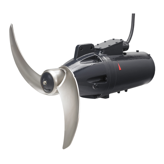
Mixers and flowmakers 50/60 hz
Hide thumbs
Also See for SMD:
- Installation and operating instructions manual (39 pages) ,
- Instructions manual (25 pages) ,
- Instructions manual (200 pages)

Related Manuals for Grundfos SMD


Summary of Contents for Grundfos SMD
- Page 1 GRUNDFOS INSTRUCTIONS SMD, SMG, SFG-Mixers and flowmakers 50/60 Hz Installation and operating instructions SMD, SMG, SFG Installation and operating instructions (all available languages) http://net.grundfos.com/qr/i/98826058...
- Page 3 SMD, SMG, SFG-Mixers and flowmakers English (GB) Installation and operating instructions ........5 Български...
- Page 4 Appendix A ..........1065 SMD, SMG, SFG-Mixers and flowmakers...
-
Page 5: Table Of Contents
Wiring diagrams for SMG and SFG ..26 ous personal injury. Wiring diagrams, SMD ... . 27 Motor protection....29... -
Page 6: Notes
2. Product introduction The symbols and notes below may appear in 2.1 Product description Grundfos installation and operating instructions, safety instructions and service instructions. The mixers are fitted with 0.9 to 18.5 kW motors. The 50 Hz flowmakers are fitted with 0.7 to 11.0 kW, and the 60 Hz versions are fitted with 0.85 to 12.1 kW... -
Page 7: Intended Use
2.3 Mixed liquids SFG flowmaker Observe the following liquid limitations to avoid overloading and exposing the mixers and flowmakers to corrosion. Pos. Description Column profile SMD, SMG, SMG.H, Depth blocker SFG.H Motor bracket pH value 4-10 Top fixation bracket including safety wire Liquid temperature * 5-40 °C... - Page 8 Grundfos. The explosion protection classifications of the SMD mixer are II 2G Ex db h IIB T4 Gb and II 2G Ex db h ib IIB T4 Gb. The classi- fication of the installation must be ap-...
-
Page 9: Identification
Application U.K Importer: Grundfos Pumps ltd. Mud, for high density Grovebury Road Leighton Buzzard Bedfordshire LU74TL Heavy duty, biogas plants Nameplate for explosion-proof SMD mixers Propeller speed 325 RPM [min Standard Installation method DK - 8850 Bjerringbro Denmark 2" thread connection... - Page 10 Place of production Reference to requirement of electric ma- chines operated with converter Manufacturer name and address Type: • SMG or SMD: Submersible mixer • SFG: Submersible flowmaker Company standard Approval mark - UKCA approved body number of production location...
- Page 11 2.4.3 Approvals The SMD mixers designed for applications in potentially explosive environments (Ex versions) are supplied with a nameplate containing certification details. SMD mixer IECEx certificate number: IECEx SEV 17.0004X. Key to certification details Directive or standard Code Description The equipment conforms to harmonized EU and UK stand- ards.
-
Page 12: Safety Instructions
When using explosion-proof mixers, ob- serve the following safety regulations. Ex marking of the SMD Ex mixers: Ex db h IIB T4 Gb. Ex marking of the SMD Ex mixer variant with leakage sensor: Ex db h ib IIB T4 Gb. For more information on leakage sensors, see 6.4 Gearbox or shaft seal... -
Page 13: Receiving The Product
See figs Mounting the lifting wire on the motor the surface protection during transportation. bracket and Mounting the lifting wire on SMD. Make sure that the mixer, flowmaker and accessories cannot roll or fall over. -
Page 14: Mounting The Product
ABOVE Tighten all nuts and bolts to the following torques: sketch for mixers. • SMD: The distance from the propeller tip to the Bolts F-class 70 Bolts F-class 80 liquid surface must be at least 1.5 times the propeller diameter. See H in fig. - Page 15 SMD.09 - 18.xx.xxxx.T. surface must be at least 0.75 times the propeller diameter. See H in fig. Positioning sketch • fixation base for floor mounting. See fig. SMD.09 - ABOVE 18.xx.xxxx.T. for flowmakers. • motor bracket for mounting on column profile. See •...
- Page 16 6. Depending on the length of the column profile, weld the turnable part of an intermediate fixation bracket (19 in fig. SMD and SMG mixers) to the column profile. 7. Position and align the column profile in the bottom fixation bracket.
- Page 17 13. Drill the holes for the anchor bolts for the crane foot (12 in fig. SMD and SMG mixers). 14. Mount the crane foot, fit and tighten the bolts. 15. Mount the lifting wire (15 in fig. Safety wire) on the motor bracket using the shackle.
- Page 18 Follow the separate installation and op- erating instructions for cranes. 19. Lift the complete mixer, motor bracket with motor, using the crane and slide it over the column profile. 20. Slowly lower the mixer into the tank and down to its position on the depth blocker.
- Page 19 touch other installations, bottom or wall. This also Pos. Description applies when the mixer is turned. See section Back support leg Positioning of mixers and flowmakers. Motor bracket DANGER Electric shock Top fixation bracket including safety wire Death or serious personal injury Crane foot ‐...
- Page 20 1. Drive the key (1) into the keyway for correct The fixation of the propeller blades is en- positioning of the blades. sured by the pressure of the clamping jaws which are tightened by the bolts (3) and 2. Apply a little oil to the blade shaft and the hole in the nuts (5).
- Page 21 2. SFG.xx.150/260 Pos. Description Place the depth blocker (3), the back support leg Screw (3b) and the front support legs (3a) in the right position, and weld them to the column profile (2). Set screw See position numbers in fig. SFG.xx.150/260, Three screws profile and support legs, back view.
- Page 22 Pos. Description Fixation plate β Column profile Depth blocker Front support leg α Back support leg 3. SFG.xx.180 and SFG.xx.230 Place the depth blocker (3), the back support leg (3b) and the front support legs (3a and 3c) in the right position, and weld them to the column profile SFG.xx.130 960 mm ≤...
- Page 23 (H) of the SFG depth blocker according to the 10. Fit the turnable metal part, now fitted on top of the positioning rules for flowmakers. See section column profile, to the already mounted top fixation Flowmakers. bracket. Tighten the bolts (A and B in fig. Top fixation) in the desired position.
- Page 24 Pos. Description Power cable Snap hook Wire clamp Lifting wire Cable clamp 19. Position the crane in the foot, and mount the lifting wire in the drum of the winch. See fig. Mounting the lifting wire in the drum. Safety wire 18.
-
Page 25: Electrical Connection
The explosion-protection classifications of 23. Remove the lifting wire from the winch and fit it to the SMD mixer are II 2G Ex db h IIB T4 Gb the wire clamp (20 in fig. Top fixation bracket with and II 2G Ex db h ib IIB T4 Gb. The classi-... -
Page 26: Wiring Diagrams For Smg And Sfg
Three-phase motors Terminals Description Ends of the three stator windings, 1, 2, 3, 4, 5, 6 (U1, V1, W1, W2, U2, V2) 11, 12 Thermal switches (F6) 21, 22 Leakage sensor in gearbox (B) Schematic drawing of delta and star connection Pos. -
Page 27: Wiring Diagrams, Smd
6.2 Wiring diagrams, SMD Marking Switch and sensor Connection Maximum load Thermal Moisture Leakage sen- Wire 4 (7 * ) Wire 6 (9 * ) Relay switch switch (M) sor (LS) 2.5 A (250 V) 2.5 V Thermistor 2.5 A (250 V) 2.5 V... - Page 28 3 x PTC + M 3 x PTO + M + LS L1 L2 L3 L1 L2 L3 1 2 3 (11) (23) 1 2 3 (31) (33) 10-wire connections Pos. Description Yellow and green 3 x PTO (standard) 3 x PTC 3 x PTO + M L1 L2 L3 L1 L2 L3 L1 L2 L3...
-
Page 29: Motor Protection
See fig. Three thermal switches, section Wiring diagrams for SMG and SFG. For details on SMD cable Ex, see the SE cable Thermal switches (F6): Ex Installation and operating instructions •... -
Page 30: Starting Method
6.6 Starting method 6.8 Protection against electro-chemical corrosion 6.6.1 SMD Two different metals or alloys cause electro-chemical Continuous operation corrosion if they are connected by an electrolyte. This applies if more than one mixer or flowmaker are Direct start is possible throughout the entire power installed in the same tank. -
Page 31: Frequency Converter Operation
If the motor is operated by a frequency • Set the frequency converter U/f ratio according to converter, the temperature class of the ex- the motor data. plosion-proof SMD mixer must be T3. Maximum For more information about frequency con- Maximum repetitive... -
Page 32: Startup
Position of the oil drain and the oil filling screws on potentially explosive environment. SMG and SFG and Position of the oil drain and the oil filling screws on SMD. CAUTION For oil quality and quantity, see section Oil quality, Sharp element gearbox or shaft seal housing. -
Page 33: Repairing The Product
8.2.1 Explosion-proof mixers Explosion-proof mixers must be serviced and repaired by Grundfos or by an approved service partner. Service work must be carried out according to EN 60079-19. -
Page 34: Service Chart
Check the power cable twice a year for surface damage. Power ca- If damaged, the cable must be replaced by Grundfos. Replace the lip seal and If the oil contains water or is If the shaft seal housing is wear ring if they are worn. -
Page 35: Oil
Dispose of used oil in accordance with 8.4.1 Oil quality, gearbox or shaft seal housing local regulations. The gear oil quality and designation for mixers (SMD, SMG) is according to DIN 51502, ISO VG 68. The 4. Clean and refit the oil drain screw (1). -
Page 36: Storing The Product
9. Storing the product Store mixers or flowmakers in a dry location in which the temperature is not exposed to major fluctuations. Do not expose the flowmaker propeller blades to direct sunlight for more than a month. If the mixer or flowmaker is stored for more than one year, change the gearbox oil. -
Page 37: Fault Finding
Clean the blades and inspect them for any Propeller blades are dirty or damaged. wear. In case the propeller blades are worn or damaged, contact Grundfos. Mixer or flowmaker Internal parts are worn. Contact Grundfos. runs unevenly and is... - Page 38 Clean the blades and inspect them for any Propeller blades are dirty or damaged. wear. In case the propeller blades are worn or damaged, contact Grundfos. noisy. Damaged motor or gearbox roller bearings. Contact Grundfos. Oscillations caused by the installation (res- Check the installation design. onance). •...
-
Page 39: Technical Data
11. Technical data 11.3 Shaft seals 11.1 Motor Sealing against leakage Two lip seals and one mechanical shaft seal made Seal Mechanical shaft seal of tungsten carbide/tungsten carbide or SiC/SiC Material, motor housing 11.4 Operating conditions Cast iron, grade 25 (EN- SMG, SFG GJL-250) Continuous operation... -
Page 40: Disposing Of The Product
This product or parts of it must be disposed of in an environmentally sound way: 1. Use the public or private waste collection service. 2. If this is not possible, contact the nearest Grundfos company or service workshop. See also end-of-life information at www.grundfos.com/product-recycling. The crossed-out wheelie bin symbol... - Page 41 Appendix A A.1. Dimensions and weights A.1.1. SMD SMD - Version T SMD mounted on slide 50 Hz Net weight * Rated power Type [kW] [mm] [mm] [mm] [mm] [mm] [kg] SMD.09.21.1478.T SMD.11.25.1470.T SMD.14.25.1460.T SMD.18.25.1440.T SMD.09.21.1478 1065...
- Page 42 Net weight * Rated power Type [kW] [mm] [mm] [mm] [mm] [mm] [kg] SMD.11.25.1470 SMD.14.25.1460 SMD.18.25.1440 SMD.19.32.985 SMD.23.37.980 SMD.28.37.975 SMD.35.37.967 With motor bracket and 10 m cable. Cable weight: 0.5 kg/m. 60 Hz Net weight * Rated power Type [kW]...
- Page 43 A.1.2. SMG 50 Hz Net weight * Rated power Type [kW] [mm] [mm] [mm] [mm] [mm] [kg] SMG.09.55.277.5.0B SMG.12.63.275.5.0B SMG.16.63.272.5.0B SMG.20.71.264.5.1B SMG.25.71.263.5.1B SMG.30.71.303.5.1B SMG.36.71.301.5.1B SMG.48.73.306.5.1B 1000 SMG.56.86.264.5.1B 1050 SMG.70.86.263.5.1B 1050 SMG.85.86.306.5.1B 1050 SMG.110.86.305.5.1B 11.0 1050 SMG.140.90.325.5.1B 14.0 1100 SMG.180.90.359.5.1B 18.0 1100 With motor bracket and 10 m cable.
- Page 44 60 Hz Rated weight * power Type [mm] [mm] [mm] [mm] [mm] [kW] [kg] SMG.09.55.275.6.0K SMG.12.63.273.6.0K SMG.16.63.270.6.0K SMG.20.71.262.6.1K SMG.25.71.261.6.1K SMG.33.71.311.6.1K SMG.38.71.309.6.1K SMG.56.86.263.6.1K 1050 SMG.70.86.262.6.1K 1050 SMG.95.86.316.6.1K 10.4 1050 SMG.120.86.315.6.1K 13.2 1050 SMG.160.90.344.6.1K 17.6 1100 SMG.09.55.276.6.0P SMG.12.63.275.6.0P SMG.16.63.273.6.0P SMG.20.71.264.6.1P SMG.25.71.263.6.1P SMG.33.71.315.6.1P SMG.40.71.314.6.1P SMG.56.86.264.6.1P 1050...
- Page 45 A.1.3. SMG.A - Agriculture SMG.A mixers are only available as 50 Hz variants. H -propeller design S - propeller design 1069...
- Page 46 Rated pow- Net weight * Propeller de- Type sign [mm] [mm] [mm] [mm] [mm] [kg] [kW] SMG.45.71.A.338.5.1B SMG.75.58.A.343.5.1B SMG.80.73.A.343.5.1B 1000 SMG.110.65.A.344.5.1B 11.0 1010 SMG.130.86.A.343.5.1B 13.0 1050 With motor bracket and 10 m cable. Cable weight: 0.5 kg/m. Maximum operating hours per year 250. 1070...
- Page 47 A.1.4. SMG.H - Heavy duty 50 Hz Net weight * Rated power Type [kW] [mm] [mm] [mm] [mm] [mm] [kg] SMG.50.65.H.265.5.1B 1050 SMG.80.65.H.306.5.1B 1050 SMG.110.65.H.344.5.1B 11.0 1050 SMG.150.78.H.325.5.1B 15.0 1100 SMG.185.78.H.358.5.1B 18.5 1100 With motor bracket and 10 m cable. Cable weight: 0.5 kg/m. 1071...
- Page 48 60 Hz Net weight * Rated power Type [kW] [mm] [mm] [mm] [mm] [mm] [kg] SMG.50.65.H.263.6.1K 1050 SMG.50.65.H.264.6.1P 1050 SMG.90.65.H.317.6.1K 1050 SMG.90.65.H.319.6.1P 1050 SMG.120.78.H.297.6.1K 13.2 1100 SMG.120.78.H.298.6.1P 13.1 1100 SMG.180.78.H.345.6.1P 19.4 1100 With motor bracket and 10 m cable. Cable weight: 0.5 kg/m. 1072...
- Page 49 A.1.5. SFG.xx.130/180/230.xx SFG.xx.130.xx SFG.xx.180.xx - 2 blade and SFG.xx.230.xx - 2 blade SFG.xx.180.xx - 3 blade and SFG.xx.230.xx - 3 blade 1073...
- Page 50 50 Hz Rated Propeller weight * power Type version [mm] [mm] [mm] [mm] [mm] [kW] [kg] SFG.07.130.50.5.0B 1300 SFG.10.130.57.5.0B 1300 SFG.14.130.64.5.0B 1300 SFG.17.130.68.5.1B 1300 SFG.22.130.74.5.1B 1300 SFG.27.130.80.5.1B 1300 SFG.33.130.85.5.1B 1300 2-blade SFG.36.130.88.5.1B 1300 SFG.07.180.32.5.0B 1200 1800 SFG.10.180.36.5.0B 1200 1800 SFG.14.180.41.5.0B 1200 1800 SFG.17.180.44.5.1B...
- Page 51 60 Hz Rated pow- Propeller weight * Type version [mm] [mm] [mm] [mm] [mm] [kW] [kg] SFG.07.130.50.6.0K 0.85 1300 SFG.10.130.57.6.0K 1300 SFG.14.130.64.6.0K 1300 SFG.17.130.68.6.1K 1300 SFG.22.130.74.6.1K 1300 SFG.29.130.82.6.1K 1300 SFG.33.130.85.6.1K 1300 SFG.36.130.88.6.1K 1300 SFG.07.130.50.6.0P 0.85 1300 SFG.10.130.57.6.0P 1300 SFG.14.130.64.6.0P 1300 2-blade SFG.17.130.68.6.1P 1300...
- Page 52 Rated pow- Propeller weight * Type version [mm] [mm] [mm] [mm] [mm] [kW] [kg] SFG.07.230.26.6.0K 0.85 1200 2300 SFG.09.230.28.6.0K 1200 2300 SFG.12.230.31.6.0K 1200 2300 2-blade SFG.16.230.35.6.0K 1200 2300 SFG.19.230.37.6.1K 1200 2300 SFG.22.230.39.6.1K 1200 2300 SFG.25.230.39.6.1K 1200 2300 SFG.32.230.42.6.1K 3-blade 1200 2300 SFG.38.230.46.6.1K 1200...
- Page 53 A.1.6. SFG.xx.260.xx SFG.xx.260.xx - 2 blades and 3 blades 50 Hz Rated pow- Net weight * Propeller ver- Type sion [mm] [mm] [mm] [mm] [mm] [kg] [kW] SFG.22.260.30.5.1B 1500 2600 SFG.27.260.32.5.1B 1500 2600 SFG.32.260.34.5.1B 1500 2600 SFG.36.260.35.5.1B 1500 2600 SFG.44.260.39.5.1B 2-blade 1500 2600...
- Page 54 Rated pow- Net weight * Propeller ver- Type sion [mm] [mm] [mm] [mm] [mm] [kg] [kW] SFG.50.260.35.6.1K 1500 2660 SFG.60.260.38.6.1K 1500 2660 3-blade SFG.72.260.40.6.1K 1500 2660 SFG.80.260.42.6.1K 1500 2660 SFG.22.260.29.6.1P 1500 2600 SFG.32.260.34.6.1P 1500 2600 2-blade SFG.36.260.35.6.1P 1500 2600 SFG.44.260.38.6.1P 1500 2600 SFG.50.260.35.6.1P...
- Page 55 A.1.7. SFG.H - Heavy duty SFG.xx.260, SFG.xx.150 - 2 blades and SFG.xx.150 - 3 blades Pos. Description SFG.xx.260 SFG.xx.150 - 2 blades SFG.xx.150 - 3 blades SFG.xx.150 propeller angle There are three possible propeller angles: • 18° • 22° • 26°...
- Page 56 Rated pow- Propeller weight * Type version [mm] [mm] [mm] [mm] [mm] [kW] [kg] SFG.70.260.H.44.6.1K 1500 2600 SFG.70.260.H.44.6.1P 1500 2600 2-blade SFG.110.260.H.51.6.1K 12.1 1500 2600 SFG.110.260.H.51.6.1P 12.0 1500 2600 With motor bracket and 10 m cable. Cable weight: 0.5 kg/m. 1080...
- Page 57 Argentina China Greece Bombas GRUNDFOS de Argentina S.A. GRUNDFOS Pumps (Shanghai) Co. Ltd. GRUNDFOS Hellas A.E.B.E. Ruta Panamericana km. 37.500industin 10F The Hub, No. 33 Suhong Road 20th km. Athinon-Markopoulou Av. 1619 - Garín Pcia. de B.A. Minhang District P.O. Box 71 Tel.: +54-3327 414 444...
- Page 58 Fax: +66-2-725 8998 Fax: + 370 52 395 431 Москва, RU-109544, Russia Turkey Тел. (+7) 495 564-88-00 (495) 737-30-00 Malaysia GRUNDFOS POMPA San. ve Tic. Ltd. Факс (+7) 495 564 8811 GRUNDFOS Pumps Sdn. Bhd. Sti. E-mail grundfos.moscow@grundfos.com 7 Jalan Peguam U1/25 Gebze Organize Sanayi Bölgesi...
- Page 59 98826058 01.2022 ECM: 1316320 www.grundfos.com...
Need help?
Do you have a question about the SMD and is the answer not in the manual?
Questions and answers