Grundfos SMD Installation And Operating Instructions Manual
Hide thumbs
Also See for SMD:
- Installation and operating instructions manual (59 pages) ,
- Instructions manual (25 pages) ,
- Instructions manual (200 pages)
Table of Contents
Advertisement
Quick Links
Advertisement
Table of Contents

Related Manuals for Grundfos SMD


Summary of Contents for Grundfos SMD
- Page 1 GRUNDFOS INSTRUCTIONS SMD, SMG, SFG mixers and flowmakers 60 Hz, North America Installation and operating instructions SMD, SMG, SFG mixers and flowmakers 60 Hz, North America Installation and operating instructions Other languages http://net.grundfos.com/qr/i/99135312...
- Page 3 SMD, SMG, SFG mixers and flowmakers English (US) Installation and operating instructions ............4 Français (CA)
-
Page 4: Table Of Contents
These warranties are Wiring diagrams for SMD ..... 23 expressly in lieu of any other warranties, express or implied, and Motor protection . -
Page 5: General Information
Children must not use or play with this product. This booklet includes instructions for installation, operation and maintenance of Grundfos SMD and SMG mixers as well as SFG flowmakers in the non-explosion-proof version and SMD mixers in the explosion-proof version. The Ex instructions must be followed for the explosion-proof SMD. -
Page 6: Product Introduction
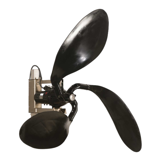
These products are designed for applications involving the mixing, that is the homogenisation and suspension of liquids. 3.3 Applications These mixers and flowmakers are intended to be used in the following areas: • municipal and industrial wastewater treatment SMD Mixer • industrial processes • sludge treatment • agriculture •... - Page 7 % dry solid SMG, SFG Activated sludge 0.5 % Sludge in selector zones 0.5 % Sludge in anoxic zones 0.5 % Sludge in bivalent zones 0.5 % Sludge in anaerobic zones 0.5 % Primary sludge ≤ 3 % Secondary sludge ≤...
-
Page 8: Identification
Ex markings and Ex certification number FM CA If a frequency converter is used. At the installation site, fix the extra nameplate that is supplied with the product. Make sure that the nameplate is visible. Nameplate of SMD, SMG and SFG... - Page 9 IP68 Enclosure class according to IEC 60529. FM warning plate 3.5.4 Approvals (cFMus) The SMD mixers have been approved by FM, and the explosion- proof versions hold FM Certificate of Conformity, numbers FM17US0078X and FM17CA0043X. 3.5.5 Approval standards The SMD mixers have been approved by FM according to: Canadian standards CSA-C22.2: No.
-
Page 10: Safety Instructions
Maintenance, service and repair To reduce the risk of ignition of hazardous atmospheres, Only Grundfos or service workshops approved by Grundfos are do not open while circuits are live. allowed to dismantle mixers. This also applies to the cable entry. -
Page 11: Maintenance
4.7 Maintenance If the product or the accessories are damaged, contact Grundfos immediately. Do not remove a damaged component, unless CAUTION instructed otherwise by Grundfos. Make sure to comply with local regulations when disposing of the Sharp element package. Minor or moderate personal injury ‐... -
Page 12: Mechanical Installation
See H in fig. Positioning sketch for mixers. ABOVE • SMD: The distance from the propeller tip to the liquid surface must be at least 1.5 times the propeller diameter. See H in fig. Positioning sketch for mixers. ABOVE •... - Page 13 See fig. SMD.09 - 18.xx.xxxx.T. • fixation bracket for wall mounting. See fig. SMD.09 - 18.xx.xxxx.T. • fixation base for floor mounting. See fig. SMD.09 - 18.xx.xxxx.T. • motor bracket for mounting on column profile. See fig. SMD and SMG mixers.
- Page 14 6. Depending on the length of the column profile, weld the turnable part of an intermediate fixation bracket (19, fig. SMD and SMG mixers) to the column profile. 7. Position and align the column profile in the bottom fixation bracket.
- Page 15 12. Fasten the depth blocker (3) in the right position. 13. Drill the holes for the anchor bolts for the crane foot (12, fig. Attaching the power cable to the lifting wire SMD and SMG mixers). 14. Mount the crane foot, and fit and tighten the bolts. Pos.
- Page 16 21. Mount the cable sock (18) to the top fixation bracket using the 6.3.4 Installing a flowmaker shackle, and pull the power cable through it to the desired position. See fig. Top fixation bracket with lifting and safety wires and cable sock.
- Page 17 6.3.4.1 Mounting the propeller blades of SFG.xx.71 - 91 Pos. Description Screw Cover plate Washer 1. Drive the key (1) into the keyway for correct positioning of the blades. 2. Apply a little oil to the blade shaft and the hole in the hub. 3.
- Page 18 2. SFG.xx.102: Place the depth blocker (3), the back support leg (3b) and the front support legs (3a) in the right position, and weld them on the column profile (2). See position numbers in fig. SFG.xx.102, profile and support legs, back view. α...
- Page 19 11. Drill the holes for the anchor bolts for the bottom fixation plates in the bottom of the tank, and insert the bolts. See fig. SFG.xx.102, profile and support legs, back view. 12. Tighten the anchor bolts in the bottom fixation plate. 13.
-
Page 20: Electrical Connection
Make sure that the power supply cannot be switched on unintentionally. http://net.grundfos.com/qr/i/96882862 26. Connect the power cable to the terminals in the control cabinet. 7. Electrical connection 20. Lift the complete flowmaker and the motor bracket with motor, using the crane and slide it over the column profile. -
Page 21: Wiring Diagrams For Smg And Sfg
The classification of the installation must be approved by the local authorities in each individual case. For the elec- trical installation, the standard ANSI/IEC 60079-14 must be met. See section 3.5.5 Approval standards. (6) (11) (12) (21) (22) The instructions in section 4.3 Explosion-proof versions must be observed. - Page 22 Three PTC sensors Terminals Description Ends of the three stator windings, (U1, V1, 1, 2, 3, 4, 5, 6 W1, W2, U2, V2) PTC sensors according to DIN 44081 (ϑ1, ϑ2, 31, 32 ϑ3) 21, 22 Leakage sensor in gearbox (B)
-
Page 23: Wiring Diagrams For Smd
L1 L2 L3 1 2 3 (11) (23) (11) (13) 1 2 3 SMD, 7-wire cable, PTO, moisture switch and leakage sensor version 10-wire connections SMD, 7-wire cable, PTO, moisture switch version SMD, 10-wire cable Pos. Description Yellow and green... -
Page 24: Motor Protection
6 months. If the oil contains water, replace the shaft seal. http://net.grundfos.com/qr/i/99421246 SMD, 10-wire cable, PTO, moisture switch, standard version For details on SMD cable Ex, see the SE cable Ex Installation and operating instructions 7.3 Motor protection Mixers and flowmakers are provided with the following types of motor protection: http://net.grundfos.com/qr/i/99952997... -
Page 25: Checking The Direction Of Rotation
(SIL 1). When using an isolation transformer, do not alter the ratio For more information about frequency converter operated between starting current and rated current. mixer or flowmaker speed and torque curves, visit the Grundfos Product Center at https://product-selec- tion.grundfos.com. -
Page 26: Startup
If required, fill oil into the gearbox or shaft seal housing through the oil-filling hole (2). See figs Position of oil drain and oil filling screws on SMD and Position of oil drain and oil filling screws on SMG and SFG. -
Page 27: Service
Before returning the product for service, contact Grundfos with details about the liquid. Otherwise, Grundfos can deny to service the product. Any application for service must include details about the liquid. -
Page 28: Service Chart
[fluid oz. (l)] 9.4.1 Oil quality, gearbox or shaft seal housing SMG.220.xx 135 (4.0) The gear oil designation for mixers, SMD and SMG, is according to SFG.xx.51.xx 44.0 (1.3) ISO VG 68. The gear oil designation for flowmakers, SFG, is according to ISO VG 220. -
Page 29: Storing The Product
Pay attention to the condition of the shaft seals, cable entry 6. Refit the screw (2). and sensors. Position of oil drain and oil filling screws on SMG and SFG Position of oil drain and oil filling screws on SMD Pos. Description Oil drain screw... -
Page 30: Fault Finding
Propeller cannot rotate freely. peller can rotate freely. Mixer or flowmaker does Stator windings are faulty. Contact Grundfos. not start. Wait until the motor is cooled, and try to restart the mix- Motor has cut out due to overheating. er or flowmaker. -
Page 31: Technical Data
1. Use the public or private waste collection service. The mixers and flowmakers are designed for continuous operation. 2. If this is not possible, contact the nearest Grundfos company or 12.1 Motor service workshop. See also end-of-life information at www.grundfos.com/product-... - Page 32 Appendix A A.1. Dimensions and weights A.1.1. SMD SMD - Version T SMD mounted on slide Rated power Net weight Type [hp (kW)] [in (mm)] [in (mm)] [in (mm)] [in (mm)] [in (mm)] [lb (kg)] SMD.13.7.1775.T.(Ex) 1.3 (1.0) 7.09 (180) SMD.17.8.1765.T.(Ex)
- Page 33 A.1.2. SMG Rated power Net weight Type [hp (kW)] [in (mm)] [in (mm)] [in (mm)] [in (mm)] [in (mm)] [lb (kg)] SMG.12.22.276. 1.2 (0.9) 30.7 (780) 7.87 (200) 12.6 (320) 16.1 (410) 21.7 (550) SMG.16.25.275. 1.6 (1.2) 179 (81) 31.1 (790) 7.87 (200) 12.6 (320) 16.1 (410)
- Page 34 A.1.3. SFG.xx.51-91.xx SFG.xx.51.xx SFG.10-39.71.xx - 2 blade SFG.10-30.91 - 2 blade and SFG.47.71, SFG.55.71, SFG.34-55.91 - 3 blade Rated Net weight Propeller ver- power Type sion [in (mm)] [in (mm)] [in (mm)] [in (mm)] [in (mm)] [lb (kg)] [hp (kW)] SFG.10.51.50.
- Page 35 Rated Net weight Propeller ver- power Type sion [in (mm)] [in (mm)] [in (mm)] [in (mm)] [in (mm)] [lb (kg)] [hp (kW)] SFG.10.91.26. 1.0 (0.7) SFG.12.91.28. 1.2 (0.9) 445 (202) SFG.16.91.31. 1.6 (1.2) 2-blade SFG.22.91.35. 2.2 (1.6) SFG.26.91.37. 2.6 (1.9) 47.2 (1200) 11.9 (302) 22.4 (570)
- Page 36 A.1.4. SFG.xx.102.xx SFG.xx.102.xx - 2 blades and 3 blades Rated pow- Net weight Propeller Type version [in (mm)] [in (mm)] [in (mm)] [in (mm)] [in (mm)] [lb (kg)] [hp (kW)] SFG.30.102.29. 3.0 (2.2) SFG.43.102.34. 4.3 (3.2) 102.4 2-blade 25.6 (650) 800 (363) (2600) SFG.48.102.35.
- Page 37 Tel.: +36-23 511 110 N-1011 Oslo Turkey E-mail: bulgaria@grundfos.bg Fax: +36-23 511 111 Tel.: +47-22 90 47 00 GRUNDFOS POMPA San. ve Tic. Ltd. Sti. Fax: +47-22 32 21 50 Gebze Organize Sanayi Bölgesi Canada India Ihsan dede Caddesi Poland GRUNDFOS Canada inc.
- Page 38 Uzbekistan Grundfos Tashkent, Uzbekistan The Representative Office of Grundfos Kazakhstan in Uzbekistan 38a, Oybek street, Tashkent Tel.: (+998) 71 150 3290 / 71 150 3291 Fax: (+998) 71 150 3292...
- Page 39 99135312 06.2022 ECM: 1338822 www.grundfos.com...
Need help?
Do you have a question about the SMD and is the answer not in the manual?
Questions and answers