Sign In
Upload
Download
Table of Contents
Contents
Add to my manuals
Delete from my manuals
Share
URL of this page:
HTML Link:
Bookmark this page
Add
Manual will be automatically added to "My Manuals"
Print this page
×
Bookmark added
×
Added to my manuals
Manuals
Brands
Grundfos Manuals
Mixer
SMD Series
Installation and operating instructions manual
Grundfos SMD Series Installation And Operating Instructions Manual
Mixers and flowmakers, 60 hz, north america
Hide thumbs
1
Table Of Contents
2
3
4
5
6
7
8
9
10
11
12
13
14
15
16
17
18
19
20
21
22
23
24
25
26
27
28
29
30
31
32
33
34
35
36
37
38
39
40
41
42
43
44
page
of
44
Go
/
44
Contents
Table of Contents
Bookmarks
Table of Contents
Table of Contents
1 Limited Warranty
2 General Information
Symbols Used in this Document
3 Safety Instructions
General Safety Instructions
Potentially Explosive Environments
Explosion-Proof Versions
Receiving the Product
Installing the Product
Starting up the Product
Servicing the Product
Fault Finding the Product
4 Receiving the Product
Inspecting the Product
5 Installing the Product
Torques
Positioning of Mixers and Flowmakers
Installing a Mixer
Installing a Flowmaker
6 Electrical Connection
Motor Protection
Gearbox or Shaft Seal Housing Protection
Starting Method
Wiring Diagrams for SMG and SFG
Wiring Diagrams for SMD
Direction of Rotation
Protection against Electro-Chemical Corrosion
Frequency Converter Operation
7 Starting up the Product
8 Handling and Storing the Product
Transporting the Product
Storing the Product
9 Product Introduction
Applications
Identification
Approvals (Cfmus)
10 Servicing the Product
Explosion-Proof Mixers
Contaminated Mixer or Flowmaker
Service Chart
Oil
Oil Change
11 Fault Finding the Product
12 Technical Data
General Technical Data
Motor
Gearbox, SMG, SFG Only
Shaft Seals
Propeller
Sound Pressure Level
13 Disposing of the Product
Advertisement
Quick Links
Download this manual
GRUNDFOS INSTRUCTIONS
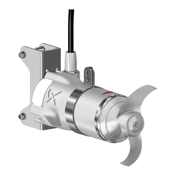
SMD, SMG, SFG
mixers and flowmakers
60 Hz, North America
Installation and operating instructions
Table of
Contents
Previous
Page
Next
Page
1
2
3
4
5
Advertisement
Table of Contents
Need help?
Do you have a question about the SMD Series and is the answer not in the manual?
Ask a question
Questions and answers
Related Manuals for Grundfos SMD Series
Mixer Grundfos SMG Series Installation And Operating Instructions Manual
Mixers and flowmakers, 60 hz, north america (44 pages)
Mixer Grundfos SMD Installation And Operating Instructions Manual
Mixers and flowmakers 50/60 hz (59 pages)
Mixer Grundfos SMD Installation And Operating Instructions Manual
(39 pages)
Mixer Grundfos AMD.07.18.1410.3 Service Instructions Manual
(9 pages)
Mixer Grundfos AMD.05-08 Installation And Operating Instructions Manual
(144 pages)
Mixer Grundfos AMG Series Installation And Operating Instructions Manual
Mixers and flowmakers (814 pages)
Mixer Grundfos AMD Series Installation And Operationg Instructions
(16 pages)
Mixer Grundfos AMG Series Service Instructions Manual
50/60 hz (24 pages)
This manual is also suitable for:
Smg series
Sfg series
Table of Contents
Print
Rename the bookmark
Delete bookmark?
Delete from my manuals?
Login
Sign In
OR
Sign in with Facebook
Sign in with Google
Upload manual
Upload from disk
Upload from URL


Need help?
Do you have a question about the SMD Series and is the answer not in the manual?
Questions and answers