Table of Contents
Advertisement
Advertisement
Table of Contents

Related Manuals for Daikin intelligent Touch Manager


Summary of Contents for Daikin intelligent Touch Manager
- Page 1 Installation Manual intelligent Touch Manager Model DCM601A71 3P291714-2B...
- Page 2 Disclosure To the User in USA Part 15 of FCC Note: This equipment has been tested and found to comply with the limits for a Class B digital device, pursuant to part 15 of the FCC Rules. These limits are designed to provide reasonable protection against harmful interference in a residential installation.
- Page 3 WARNING • Only qualified personnel must carry out the installation work. • Consult your Daikin dealer regarding relocation and reinstallation of the con- troller. Improper installation work may result in electric shocks or fire. • Install the controller in accordance with the instructions in the installation man- ual.
- Page 4 • Install the control wires for the controller at least 3.5 feet (1 meter) away from televisions or radios to prevent image interference or noise. Depending on the radio waves, a distance of 3.5 feet (1 meter) may not be sufficient to eliminate the noise. Installation Manual 3P291714-2B English DCM601A71 intelligent Touch Manager...
-
Page 5: Table Of Contents
Connecting power supply ......................23 2.7.1 Terminal location and schematic connection diagram ........... 23 2.7.2 Wiring specifications ...................... 24 Secure installation of intelligent Touch Manager ..........25 Wall mounting .......................... 25 3.1.1 Parts to be used ......................25 3.1.2 Installation procedure ....................26... - Page 6 3.3.3 Installation procedure ....................30 Basic setup of intelligent Touch Manager ............32 Setting backup battery to ON ....................32 Turning on power supply for intelligent Touch Manager and air conditioners ......32 Setting up locale ........................33 Setting time zone ........................33 Setting current time and daylight saving time ................
-
Page 7: Before Installation
• Check that the intelligent Touch Manager comes with all accessories. • Confirm where the terminals and switches of the intelligent Touch Manager are located. • Check that an appropriate space for installing the intelligent Touch Manager is available. -
Page 8: Understanding External Dimensions
Understanding external dimensions • intelligent Touch Manager body 10-3/32 10-23/32 31/32 31/32 3/16 3/16 3/16 3/16 11-13/32 (in.) • Wall mounting metal plate 9-7/32 2-3/8 1-9/16 (in.) Thickness 1/32 Installation Manual 3P291714-2B English DCM601A71 intelligent Touch Manager... - Page 9 • Frame bracket 11-3/32 9-1/2 2-7/16 9/32 8-27/32 Thickness 1/16 (in.) • Angle bracket 1-1/8 15/32 25/32 1-23/32 Thickness 1/16 (in.) English Installation Manual 3P291714-2B DCM601A71 intelligent Touch Manager...
-
Page 10: Understanding Where Terminals And Switches Are Located
1.3.1 Rear face Most terminals are located on the rear face of the intelligent Touch Manager. However, they are covered with a terminal cover for safety reasons. Remove 2 screws to detach the cover, and you can see various types of ports (terminals). -
Page 11: Front Panel
Located below the monitor display on the front panel are four LEDs that indicate the oper- ating status of the intelligent Touch Manager. Sliding the front slide cover down and then removing a screwed cover reveals terminals used during the setup after installation or during maintenance work. -
Page 12: Side Face
1.3.3 Side face On the left side of the intelligent Touch Manager, there is a USB port. The USB port is used for making settings, performing maintenance or other operations after the installation of the intelligent Touch Manager is completed. Also, on this side a label is attached on which the information such as product name, weight, power supply and serial number are printed. -
Page 13: Determining Installation Place
Determining installation place Be sure to install the intelligent Touch Manager in a place that meets the conditions described in 1.4.1 to 1.4.3. 1.4.1 Installation place and mounting direction Below are the description of the installation place and mounting direction. Be sure to confirm. -
Page 14: Electric Wiring
This chapter describes the procedure for connecting the intelligent Touch Manager with DAIKIN air conditioning devices and other equipment. In addition to air conditioners, the intelligent Touch Manager can monitor and control a wide range of equipment. However, the required connection procedures vary depending on the equipment to be connected. -
Page 15: Terminal Location And Schematic Connection Diagram
Make sure that the wires you are connecting to the F1 and F2 terminals are not power wires. Inadvertently connecting power wires to these terminals results in a failure of the air conditioner or intelligent Touch Manager. <Conceptual connection diagram with air conditioning equipment>... -
Page 16: Wiring Specifications
• Where Interface for use in BACnet is installed in parallel. • Where Interface for use in LONWORKS is installed in parallel. • If there is another intelligent Touch Manager or iTM plus adaptor which is assigned to MASTER. Installation Manual 3P291714-2B... -
Page 17: Connecting A Lan Cable
WARNING Do not clamp the LAN cable with high current cables. NOTE For how to connect the intelligent Touch Manager to a PC network, contact your net- work administrator. English Installation Manual 3P291714-2B... -
Page 18: Terminal Location And Schematic Connection Diagram
2.3.1 Terminal location and schematic connection diagram Using a LAN cable, connect the LAN port to the network hub. <LAN connection schematic diagram> Rear face of intelligent Touch Manager LAN cable 2.3.2 Wiring specifications • Applicable cable standard: 100Base-TX or 10Base-T •... -
Page 19: Connecting I/O Module
Connecting I/O module In combination with the I/O module, the intelligent Touch Manager can monitor and control a maximum of 960 contacts of non-DAIKIN peripheral devices such as lighting equipment and security systems. Connect the intelligent Touch Manager to the termination of the RS-485 wiring. -
Page 20: Address Setup
(EM11A026))”. Connecting an emergency stop input device or power meter The intelligent Touch Manager can perform operations such as an emergency stop of air conditioners according to the external signal input device, and an electricity usage calcu- lation for each air conditioner (for power proportional distribution) according to the pulse inputs from a power meter. -
Page 21: Wiring Specifications
If you have many air conditioners, use iTM plus adaptors to connect them. It is a fact that the number of indoor groups you can control using a single intelligent Touch Manager is limited to 64. By using iTM plus adaptors, you can add 64 indoor unit groups per iTM plus adaptor. -
Page 22: Terminal Location And Schematic Connection Diagram
Connect the iTM plus adaptor to the plus ADP IF terminal located on the rear face. Con- nect the intelligent Touch Manager to the plus ADP IF terminal. As the terminals have polarity, be sure to connect the positive wire to the “+” terminal and the negative wire to the “–”... -
Page 23: Connecting Power Supply
Connecting power supply Connect the intelligent Touch Manager to an power supply. WARNING Be sure to perform the operation during power-off conditions. Do not turn the power supply on until all connections are made. Not doing so may cause an electric shock. -
Page 24: Wiring Specifications
• The power supply requires earth leakage breaker installation and earth wire connection. After installing an earth leakage breaker, be sure to connect only the intelligent Touch Manager to it. • To prevent accidents due to wire breakage or disconnection, secure the power supply cables to the blue resin cable mount with cable ties. -
Page 25: Secure Installation Of Intelligent Touch Manager
Secure installation of intelligent Touch Manager There are the following three ways to install the intelligent Touch Manager. • Wall mounting: Fix the intelligent Touch Manager to the metal plate which is attached to the wall. • Flush wall mounting: Embed the back of the intelligent Touch Manager into the wall using the frame bracket and angle brackets. -
Page 26: Installation Procedure
• Secure the round-head wood screws at four points. <Wall mounting installation> N IT NOTE • How to use the P-tight screw Screw in from the bottom of the intelligent Touch Manager. Remove the rear cover before starting installation. Wall P-tight screw Round-head wood screw... -
Page 27: Flush Wall Mounting
Flush wall mounting 3.2.1 Parts to be used To flush-mount the intelligent Touch Manager to the wall, use the following accessory mounting parts: • Frame bracket, 1 pc. • Angle bracket, 2 pcs. • Flat-head screw (M4×40), 4 pcs. • Pan-head screw (M4×14, with spring washer and plain washer), 4 pcs. -
Page 28: Installation Procedure
When securing the frame bracket, be careful not to drop the angle brackets inside the wall. 2. Remove the front panel from the front face of the intelligent Touch Manager. The front panel is originally attached to the monitor screen. - Page 29 Front panel Main body 3. Insert the intelligent Touch Manager into the frame bracket attached to the wall and fix the intelligent Touch Manager to the frame bracket using four screw holes around the monitor screen and the pan-head screws.
-
Page 30: Mounting To Control Enclosure
2. Insert the intelligent Touch Manager into the opening of the control enclosure and install it to the control enclosure using the pan-head screws. 3. Attach the front panel of the intelligent Touch Manager back to its original position. Installation Manual 3P291714-2B... - Page 31 N IT Pan-head screw CAUTION If the intelligent Touch Manager is directly mounted to the control enclosure, you will be exposed to the power line connection terminals when opening the control enclosure door. Touching electrical junctions by hand may result in an electric shock. Attach the terminal cover to the rear face for your safety.
-
Page 32: Basic Setup Of Intelligent Touch Manager
The setting assignment made through this procedure may be changed at a later time. Setting backup battery to ON To retain the settings even in the event of a power outage, the intelligent Touch Manager has a built-in battery. This battery is disabled by default. So first you need to change the battery setting to ON. -
Page 33: Setting Up Locale
Set up the local standard time zone you want to use for the system clock. <Time Zone Settings screen> 1. On the Time Zone Settings screen, select the time zone of desired region from the list box. 2. Touch OK. The Time/DST Setup screen appears. English Installation Manual 3P291714-2B DCM601A71 intelligent Touch Manager... -
Page 34: Setting Current Time And Daylight Saving Time
If you see any problem, touch the Refresh button to reload the up to data information, or review the DIII address settings. 2. When the confirmation dialog appears, touch Yes. The intelligent Touch Manager restarts and Main screen appears. The intelligent Touch Manager setup has now been completed. NOTE When iTM plus adaptor is connected, power on the iTM plus adaptor in advance. -
Page 35: Setting Diii-Net Address For Each Air Conditioner
The followings are the names of buttons and display area of the navigation remote control- ler. <Navigation Remote controller> Liquid-crystal display (with backlight) Up button Menu / OK button Right button Cancel button Down button English Installation Manual 3P291714-2B DCM601A71 intelligent Touch Manager... -
Page 36: Setting Address With Wired Remote Controller
” when the intelligent Touch Manager is not powered on. Power on the intelligent Touch Manager and wait for a while before trying to operate the remote controller. You cannot change the parameter number to “ ” also when the intel- ligent Touch Manager is not communicating with the indoor units normally. - Page 37 The DIII-NET address has been set. <Step 5> GROUP SETTING 6. Press the Inspection/Test Operation button. You are now brought back to the screen shown in Step 6-2. <Step 6-1> GROUP SETTING <Step 6-2> English Installation Manual 3P291714-2B DCM601A71 intelligent Touch Manager...
-
Page 38: Setting Address With Navigation Remote Controller
The “Group Address” menu is not displayed when the intelligent Touch Manager is not powered on. Power on the intelligent Touch Manager and wait for a while before trying to operate the remote controller. The “Group Address” menu is not displayed also when the intelligent Touch Manager is not communicating with the indoor units normally. -
Page 39: Setting An Unique Address To Each Unit (When Power Proportional Distribution (Option) Is Used)
When power distribution is enabled, you need to set a unique address for each unit. For how to set an address, refer to the “Commissioning Manual Supplementary Volume (Power Proportional Distribution (EM11A027))”. English Installation Manual 3P291714-2B DCM601A71 intelligent Touch Manager... -
Page 40: Quick Operation Guide
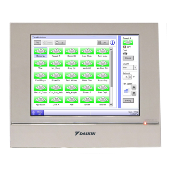
Quick Operation Guide This chapter describes how to start/stop the areas and management points registered with the intelligent Touch Manager and display their information quickly. For detailed oper- ation procedures, refer to the “User’s Manual (EM11A017)”. Viewing target area and management point information in... -
Page 41: Starting/Stopping An Area Or Management Point
Select Start or Stop in the On/Off buttons. When operation is started, the icon color changes to green or red (depending on the system setting). When operation is stopped, the color changes to grey. English Installation Manual 3P291714-2B DCM601A71 intelligent Touch Manager... - Page 44 3P291714-2B EM11A018A (1306) HT...
Need help?
Do you have a question about the intelligent Touch Manager and is the answer not in the manual?
Questions and answers