Table of Contents
Advertisement
Advertisement
Table of Contents

Related Manuals for Daikin intelligent Touch Manager DCM601B71


Summary of Contents for Daikin intelligent Touch Manager DCM601B71
- Page 1 Installation Manual intelligent Touch Manager Model DCM601B71 3P291714-8H...
- Page 2 Disclosure To the User in USA Part 15 of FCC This device complies with part 15 of the FCC Rules. Operation is subject to the following two conditions: (1) This device may not cause harmful interference. (2) This device must accept any interference received, including interference that may cause undesired operation.
- Page 3 WARNING • Only qualified personnel must carry out the installation work. • Consult your Daikin dealer regarding relocation and reinstallation of the con- troller. Improper installation work may result in electric shocks or fire. • Install the controller in accordance with the instructions in the installation man- ual.
- Page 4 CAUTION • Keep water out of the controller. • To avoid electric shock due to entry of water or insects, fill the wiring through- hole with putty. • Do not wash the controller with water as it may result in electrical shocks or fire.
-
Page 5: Table Of Contents
Contents Before Installation ....................7 Checking that all accessories are included ................7 Understanding external dimensions ..................8 Understanding where terminals and switches are located ............10 1.3.1 Rear face ........................10 1.3.2 Front panel ........................11 1.3.3 Side face ........................12 1.3.4 Wiring of cables ...................... - Page 6 Secure installation of intelligent Touch Manager ..........26 Wall mounting .......................... 26 3.1.1 Parts to be used ......................26 3.1.2 Installation procedure ....................27 Flush wall mounting ......................... 28 3.2.1 Parts to be used ......................28 3.2.2 Wall opening dimensions ....................28 3.2.3 Installation procedure ....................
-
Page 7: Before Installation
Checking that all accessories are included Based on the following accessory list, check that all accessories for the intelligent Touch Manager are included. If there is any missing or defective part, contact your DAIKIN dealer where you purchased the product. -
Page 8: Understanding External Dimensions
Understanding external dimensions • intelligent Touch Manager body 10-3/32 10-23/32 31/32 31/32 3/16 3/16 3/16 3/16 11-13/32 (in.) • Wall mounting metal plate 9-7/32 2-3/8 1-9/16 (in.) Thickness 1/32 Installation Manual 3P291714-8H English DCM601B71 intelligent Touch Manager... - Page 9 • Frame bracket 11-3/32 9-1/2 2-7/16 9/32 8-27/32 Thickness 1/16 (in.) • Angle bracket 1-1/8 15/32 25/32 1-23/32 Thickness 1/16 (in.) English Installation Manual 3P291714-8H DCM601B71 intelligent Touch Manager...
-
Page 10: Understanding Where Terminals And Switches Are Located
[DIII] The communication line connection terminals for “DIII-NET”, which enables communications with DAIKIN’s air conditioning equipment. [LINE, PHONE] The port used when subscribing to the DAIKIN “Air Conditioning Network Service System” online monitoring service for air-conditioning systems. To use the “Air Conditioning Network Service System” service, you need to sign a sepa- rate maintenance contact. -
Page 11: Front Panel
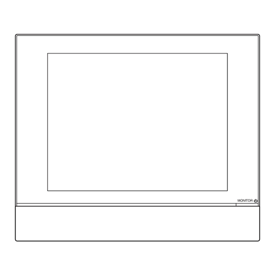
1.3.2 Front panel Located below the monitor display on the front panel are four LEDs that indicate the oper- ating status of the intelligent Touch Manager. Sliding the front slide cover down and then removing a screwed front switch cover reveals terminals used during the setup after instal- lation or during maintenance work. -
Page 12: Side Face
1.3.3 Side face On the left side of the intelligent Touch Manager, there is a USB port. The USB port is used for making settings, performing maintenance or other operations after the installation of the intelligent Touch Manager is completed. Also, on this side a label is attached on which the information such as product name, weight, power supply and serial number are printed. -
Page 13: Determining Installation Place
Determining installation place Be sure to install the intelligent Touch Manager in a place that meets the conditions described in 1.4.1 to 1.4.3. 1.4.1 Installation place and mounting direction Below are the description of the installation place and mounting direction. Be sure to confirm. -
Page 14: Electric Wiring
Electric Wiring This chapter describes the procedure for connecting the intelligent Touch Manager with DAIKIN air conditioning devices and other equipment. In addition to air conditioners, the intelligent Touch Manager can monitor and control a wide range of equipment. However, the required connection procedures vary depending on the equipment to be connected. -
Page 15: Removing The Power Supply Terminal Cover
Power supply terminal cover Connecting DIII-NET-compatible air conditioning equipment DIII-NET is the DAIKIN’s original communication method used between air conditioners. Using DIII-NET, you can centrally control multiple DAIKIN DIII-NET-compatible air condi- tioning devices by connecting them to your intelligent Touch Manager. - Page 16 <Conceptual connection diagram with air conditioning equipment> N, P N, P N, P N, P N, P N, P N, P N, P N, P N, P Outdoor unit OUT - OUT communication (terminal) IN - OUT communication (terminal) Indoor unit A maximum of 16 indoor units can be connected per remote controller group.
-
Page 17: Wiring Specifications
Precautions for using multiple centralized controllers The “centralized controller” refers to the equipment (e.g. the intelligent Touch Manager) that controls multiple air conditioners. Besides the intelligent Touch Manager, the DAIKIN’s product portfolio includes a wide range of centralized controllers suitable for different applications or building sizes, which can be used in combination to construct an optimal air conditioning control system. -
Page 18: Connecting A Lan Cable
<DIII MASTER> To change the setting of the intelligent Touch Man- ager to SLAVE, turn the DIII MASTER switch located under the front slide cover. Placing the DIII MASTER switch in the upper position (labeled as “SLAVE”) changes it to a SLAVE. When installing multiple centralized controllers, set only the highest-priority controller to MASTER and all other controllers to SLAVE according to the following order of priority. -
Page 19: Terminal Location And Schematic Connection Diagram
2.3.1 Terminal location and schematic connection diagram Using a LAN cable, connect the LAN port to the network hub. <LAN connection schematic diagram> Rear face of intelligent Touch Manager LAN cable 2.3.2 Wiring specifications • Applicable cable standard: 100Base-TX or 10Base-T •... -
Page 20: Connecting I/O Module
In combination with the I/O module, the intelligent Touch Manager can monitor and control a maximum of 960 contacts of non-DAIKIN peripheral devices such as lighting equipment and security systems. Connect the intelligent Touch Manager to the termination of the RS-485 wiring. -
Page 21: Address Setup
2.4.3 Address setup <Bus coupler> The bus coupler located at the left end of nodes has rotary switches for setting the addresses. Set a unique address for each node. For details, refer to the “Commissioning Manual Supplementary Volume (External Management Points (EM11A026))”. -
Page 22: Wiring Specifications
2.5.2 Wiring specifications • Cable type: CPEV cable • Core thickness: AWG 22-19 • Cable length: 656 ft. or less <Pulse width> Pulse width: 20 to 400 ms Pulse interval: 100 ms or more CAUTION • The contact connected to the contact input terminal must be capable of han- dling 10 mA at 16 VDC. -
Page 23: Terminal Location And Schematic Connection Diagram
2.6.1 Terminal location and schematic connection diagram Connect the iTM plus adaptor to the plus ADP IF terminal located on the rear face. Con- nect the intelligent Touch Manager to the plus ADP IF terminal. As the terminals have polarity, be sure to connect the positive wire to the “+” terminal and the negative wire to the “–”... -
Page 24: Connecting Power Supply
Connecting power supply Connect the intelligent Touch Manager to an power supply. WARNING Be sure to perform the operation during power-off conditions. Do not turn the power supply on until all connections are made. Not doing so may cause an electric shock. -
Page 25: Attaching The Rear Cover
2.7.3 Attaching the rear cover After you finish routing the cables, close the power supply terminal cover, then attach the terminal cover and power supply terminal cover. 2.7.4 Wiring specifications • Cable length: 328 ft. or less • Cable type: Ordinary tough rubber sheathed cord (60245 IEC 53) equivalent or higher Ordinary polyvinyl chloride sheathed cord (60227 IEC 53) equivalent or higher •... -
Page 26: Secure Installation Of Intelligent Touch Manager
Secure installation of intelligent Touch Manager There are the following three ways to install the intelligent Touch Manager. • Wall mounting: Fix the intelligent Touch Manager to the metal plate which is attached to the wall. • Flush wall mounting: Embed the back of the intelligent Touch Manager into the wall using the frame bracket and angle brackets. -
Page 27: Installation Procedure
3.1.2 Installation procedure CAUTION • The wall mounting metal plate has a number of holes for attaching the round- head wood screws. Though you can use any of these holes to fix the plate, we recommend you to use ones closer to the edge in order to prevent wobbling. •... -
Page 28: Flush Wall Mounting
Flush wall mounting 3.2.1 Parts to be used To flush-mount the intelligent Touch Manager to the wall, use the following accessory mounting parts: • Frame bracket, 1 pc. • Angle bracket, 2 pcs. • Flat-head screw (M4×40), 4 pcs. • Pan-head screw (M4×14, with spring washer and plain washer), 4 pcs. (Check that there are all accessories listed in section 1.1: see the accessories included with intelligent Touch Manager C.) 3.2.2... -
Page 29: Installation Procedure
3.2.3 Installation procedure 1. Insert the mounting frame bracket and angle brackets into the wall opening and secure them to the wall in such a manner that the wall is sandwiched between the brackets with flat-head screws. NOTE • You need to route in advance the cables connected to the rear face of the intelligent Touch Manager through the cable hole provided at the bottom of the frame bracket. - Page 30 <Removing front panel> N IT Front panel Main body 3. Insert the intelligent Touch Manager into the frame bracket attached to the wall and fix the intelligent Touch Manager to the frame bracket using four screw holes around the monitor screen and the pan-head screws. NOTE •...
-
Page 31: Mounting To Control Enclosure
Mounting to control enclosure 3.3.1 Parts to be used To mount the intelligent Touch Manager directly to the control enclosure, use the following accessory mounting parts: • Pan-head screw (M4×40, with spring washer and plain washer), 4 pcs. • Nut (φ4), 4 pcs. 3.3.2 Wall opening dimensions Use the following dimensional drawing to provide a sufficient opening. - Page 32 <Installing intelligent Touch Manager body to control enclosure> N IT Pan-head screw CAUTION If the intelligent Touch Manager is directly mounted to the control enclosure, you will be exposed to the power line connection terminals when opening the control enclosure door. Touching electrical junctions by hand may result in an electric shock.
-
Page 33: Basic Setup Of Intelligent Touch Manager
Basic setup of intelligent Touch Manager After checking that all connections are completed, start the intelligent Touch Manager basic setup. The basic setup refers to the preparative settings for monitoring and control- ling the air conditioning system using the intelligent Touch Manager. Make each setting by following the guidance displayed on the screen after you turn on the power supply of the intelligent Touch Manager. -
Page 34: Setting Up Locale
Setting up locale Set the display type of date/time, unit of temperature, decimal point type, etc. <Locale Settings screen> 1. [LOCALE] Set the following items on the screen. [Date] Select the date display format. [Time] Select the time display format (24-hour or 12-hour clock). [Celsius / Fahrenheit] Select the temperature display unit (Celsius or Fahrenheit). -
Page 35: Setting Current Time And Daylight Saving Time
Setting current time and daylight saving time Adjust the clock and set up the daylight saving time schedule. <Time/DST Setup screen> 1. On the Time/DST Setup screen, set up the date/time and the daylight saving time schedule. (Enable or disable the daylight saving time function. If enabled, select the start time and the end time.) 2. -
Page 36: Setting Diii-Net Address For Each Air Conditioner
Setting DIII-NET address for each air conditioner The DIII-NET system has the control address used to identify each air conditioner group. This is called “DIII-NET address”. You must set the DIII-NET address manually using the remote controller of air conditioner. There are several types of the remote controller, and the setting method differs depending on the controller type. -
Page 37: Setting Address With Wired Remote Controller
4.7.2 Setting address with wired remote controller The operation procedure of the wired remote controller is as follows. NOTE After power-on, the controller shows the symbol “ ” for about 1 minute after displaying all information on its display. During this period, it may not accept your operation. If so, try operating the remote controller again after “... - Page 38 4. Using the Programming time buttons, select the address you want to set. <Step 4> GROUP SETTING 5. Press the SCHEDULE button to make the “GROUP” indicator stay lit. The DIII-NET address has been set. <Step 5> GROUP SETTING 6. Press the Inspection/Test Operation button. You are now brought back to the screen shown in Step 6-2.
-
Page 39: Setting Address With Navigation Remote Controller
4.7.3 Setting address with navigation remote controller The operation procedure of the navigation remote controller is as follows. NOTE You cannot perform the following procedure when the display backlight is off. In this case, press any key to turn on the backlight before starting the procedure. 1. -
Page 40: Setting An Unique Address To Each Unit (When Power Proportional Distribution (Option) Is Used)
5. Using the Up/Down buttons, select the address you want to set. <Step 5> Group Address (Group) Gr Addr. Release 1-00 Change 6. Press the Menu/OK button. The indication changes from “Release” to “Set” and the DIII-NET address is set. <Step 6>... -
Page 41: Quick Operation Guide
Quick Operation Guide This chapter describes how to start/stop the areas and management points registered with the intelligent Touch Manager and display their information quickly. For detailed oper- ation procedures, refer to the “User’s Manual (EM11A017)”. Viewing target area and management point information in list format List Icon... -
Page 42: Starting/Stopping An Area Or Management Point
Starting/stopping an area or management point (1) Select the area or management point you want to start or stop. (2) Select Start or Stop in the On/Off buttons. When operation is started, the icon color changes to green or red (depending on the system setting). When operation is stopped, the color changes to grey. - Page 44 3P291714-8H EM21A029A (2205) HT...
Need help?
Do you have a question about the intelligent Touch Manager DCM601B71 and is the answer not in the manual?
Questions and answers