Table of Contents
Advertisement
Quick Links
Advertisement
Table of Contents

Subscribe to Our Youtube Channel
Related Manuals for Tech Controllers EU-293v2


Summary of Contents for Tech Controllers EU-293v2
- Page 1 EU-293 user’s manual EU-293v2...
-
Page 2: Table Of Contents
TECH TABLE OF CONTENTS Safety .................................... 3 Device description ................................ 4 III. How to install the controller ............................5 How to install battery-powered regulator ....................... 5 How to install 230V-powered regulator ........................7 Wireless controller receiver ............................9 First start-up ................................10 How to use the controller ............................ -
Page 3: Safety
EU-293 user’s manual SAFETY Before using the device for the first time the user should read the following regulations carefully. Not obeying the rules included in this manual may lead to personal injuries or controller damage. The user’s manual should be stored in a safe place for further reference. -
Page 4: Device Description
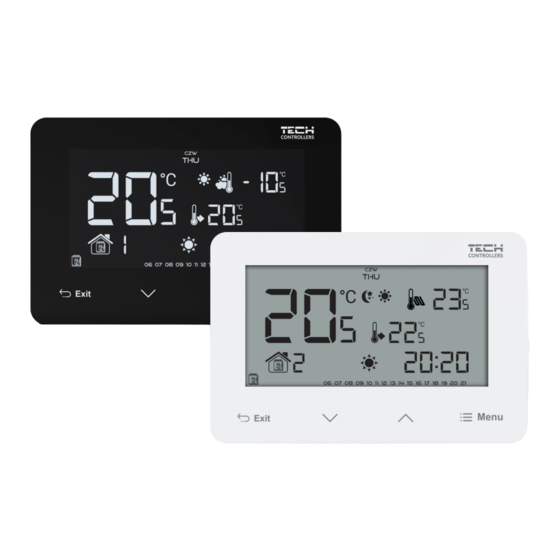
TECH DEVICE DESCRIPTION The EU-293v2 room regulator is intended for controlling the heating or cooling device (e.g. gas, oil or electric boiler or the boiler controller). Its main task is to maintain the pre-set temperature in the flat by sending a signal to the heating/cooling device (contact opening) when the desired temperature is reached. -
Page 5: How To Install The Controller
EU-293 user’s manual The EU-293v2 works with an additional EU-MW-3 signal receiver (included in the controller set), mounted near the heating device. Hardware versions: 1. EU-293 B v2 – wireless version, powered with two AAA 1,5V batteries, with a temporary backlight. - Page 6 TECH The EU-293v2 room regulator - connection diagram In order to install the device properly, follow the diagram below. A two-core communication cable should be connected to appropriate ports in the receiver. heating device...
-
Page 7: How To Install 230V-Powered Regulator
EU-293 user’s manual The EU-293v2 room regulator may be used as a wall-mountable panel. In order to mount it, place the rear part of the controller in the mounting box on the wall, insert the regulator and turn it slightly. - Page 8 TECH The EU-293v2 room regulator - connection diagram In order to install the device properly, follow the diagram below. A two-core communication cable should be connected to appropriate ports in the receiver. heating device...
-
Page 9: Wireless Controller Receiver
WIRELESS CONTROLLER RECEIVER The EU-293v2 regulator communicates with the heating device (or the CH boiler controller) by means of a radio signal sent to the EU-MW-3 receiver. Such a receiver is connected to the heating device (or the CH boiler controller) by means of a two-core cable, and communicates with the room regulator using a radio signal. -
Page 10: First Start-Up
TECH FIRST START-UP In order for the EU-293v2 controller to operate correctly, follow these steps when starting the device for the first time: 1. Insert the batteries - in order to do it, remove the front cover (battery-powered version). 2. If the room regulator is to control the floor heating system, connect an additional sensor to the floor sensor connector. - Page 11 EU-293 user’s manual In order to activate this mode, press EXIT button until day/night mode icon appears on the main screen. Day/night mode icon Weekly control This mode enables the user to define the time when the pre-set comfort temperature and the pre-set economical temperature will apply.
- Page 12 TECH Example 1 – manual mode activation in Day/night mode When Day/night mode is active, the user changes the pre-set temperature by pressing one of the buttons which automatically activates manual mode. The controller returns to Day/night mode when daytime changes into nighttime (or the other way round) or when the user presses EXIT Manual mode icon Day/night mode icon...
-
Page 13: Main Screen View And Description
EU-293 user’s manual 3. MAIN SCREEN VIEW AND DESCRIPTION The user operates the device using touch buttons. While one parameter is being edited, the remaining icons are not displayed. 1. Display 2. EXIT in the main screen view - press this button to activate the weekly control or day/night mode. In the controller menu, use this button to confirm the settings and return to the main screen view. -
Page 14: Controller Functions
TECH 1. Day of the week 2. An icon informing about current economical temperature (resulting from weekly control or day/night mode settings). 3. An icon informing about current comfort temperature (resulting from weekly control or day/night mode settings). 4. An icon informing about displaying current floor temperature (point 6 on the display) - a floor sensor must be and registered in the controller menu. -
Page 15: Block Diagram - Main Menu
EU-293 user’s manual 4.1. BLOCK DIAGRAM - MAIN MENU Day of the week Clock settings Day from... Night from... Button lock Optimum start Automatic manual mode Weekly program Pre-set comfort temperature Pre-set economical temperature Pre-set temperature hysteresis Temperature sensor calibration Registration Floor sensor Maximum floor temperature*... -
Page 16: Clock Settings
TECH 4.3. CLOCK SETTINGS In order to set current time, press MENU until time setting panel is displayed on the screen. By pressing set the hour and minutes. Press MENU to confirm and move on to the next parameter or press EXIT to confirm and return to the main screen view. -
Page 17: Automatic Manual Mode
EU-293 user’s manual Room temperature - Room temperature - OPTIMUM START OFF OPTIMUM START ON – pre-programmed change from economical temperature to comfort temperature Activating this function means that at the time of pre-programmed change of the pre-set temperature determined by the schedule, the current room temperature will be close to the desired value. - Page 18 TECH HOW TO CONFIGURE PARTICULAR WEEKLY PROGRAMS Weekly program allows the user to define the time when comfort temperature and economical temperature will apply. Depending on the program number, the user may set daily temperature values for all days of the week (programs 1÷3), for weekdays and the weekend separately (programs 4÷6) and for each day of the week separately (programs 7÷9).
-
Page 19: Pre-Set Comfort Temperature
EU-293 user’s manual STEP 3 – ASSIGN COMFORT TEMPERATURE OR ECONOMICAL TEMPERATURE TO PARTICULAR HOURS An hour which is being edited is displayed on the controller screen. In order to assign comfort temperature, press . In order to select economical temperature, press . -
Page 20: Pre-Set Temperature Hysteresis
TECH 4.12. PRE-SET TEMPERATURE HYST ERESIS Room temperature hysteresis defines the pre-set temperature tolerance in order to prevent undesired oscillation in case of small temperature fluctuation (within the range of 0,2 ÷ 4°C). In order to set the hysteresis, press MENU until the hysteresis setting screen opens up. -
Page 21: Maximum Floor Temperature
EU-293 user’s manual 4.16. MAXIMUM FLOOR TEMPERATURE In order to set the maximum floor temperature, enable floor heating and press MENU until the maximum floor temperature screen opens up. Next, use to set the maximum temperature. To confirm, press the MENU button (confirm and go on to edit the next parameter) or press EXIT to confirm and return to the main screen view. -
Page 22: Technical Data
TECH HEAT/ COOL mode This function enables the user to select the operation mode of the room regulator: COOL - controlling a cooling system HEAT - controlling a heating system Use the buttons to select the type of system to be controlled. To confirm, press the MENU button (confirm and go on to edit the next parameter) or press EXIT to confirm and return to the main screen view. - Page 23 EU-293 user’s manual EU-MW-3 Supply voltage 230V ± 10% / 50Hz Operation temperature 5°C ÷ 50°C Maximum power consumption <1W 230V AC / 0,5A (AC1) * Potential-free cont. nom. out. load 24V DC / 0,5A (DC1) ** Operation frequency 868MHz Maximum transmitting power 25mW * AC1 load category: single-phase, resistive or slightly inductive AC load.
- Page 24 TECH...
Need help?
Do you have a question about the EU-293v2 and is the answer not in the manual?
Questions and answers