Table of Contents
Advertisement
Quick Links
© Copyright 2013 - 2016
EVERTZ MICROSYSTEMS LTD.
5292 John Lucas Drive
Burlington, Ontario
Canada L7L 5Z9
Phone:
905-335-3700
Sales:
sales@evertz.com
Tech Support:
service@evertz.com
Web Page:
www.evertz.com
Version 1.1, September 2016
The material contained in this manual consists of information that is the property of Evertz Microsystems and is intended solely for the use of
purchasers of the 7706LT series product. Evertz Microsystems expressly prohibits the use of this manual for any purpose other than the operation
of the 7706LT series product. Due to on going research and development, features and specifications in this manual are subject to change without
notice.
All rights reserved. No part of this publication may be reproduced without the express written permission of Evertz Microsystems Ltd. Copies of
this manual can be ordered from your Evertz dealer or from Evertz Microsystems.
7706LT Series
Extended L-Band Fiber Transmitter
USER MANUAL
Fax: 905-335-3573
Fax: 905-335-7571
Advertisement
Table of Contents

Related Manuals for evertz 7706LT Series


Summary of Contents for evertz 7706LT Series
- Page 1 Version 1.1, September 2016 The material contained in this manual consists of information that is the property of Evertz Microsystems and is intended solely for the use of purchasers of the 7706LT series product. Evertz Microsystems expressly prohibits the use of this manual for any purpose other than the operation of the 7706LT series product.
- Page 2 This page left intentionally blank...
- Page 3 IMPORTANT SAFETY INSTRUCTIONS The lightning flash with arrowhead symbol within an equilateral triangle is intended to alert the user to the presence of uninsulated “Dangerous voltage” within the product’s enclosure that may be of sufficient magnitude to constitute a risk of electric shock to persons. The exclamation point within an equilateral triangle is intended to alert the user to the presence of important operating and maintenance (Servicing) instructions in the literature accompanying the product.
- Page 4 WARNING Changes or Modifications not expressly approved by Evertz Microsystems Ltd. could void the user’s authority to operate the equipment. Use of unshielded plugs or cables may cause radiation interference. Properly shielded interface cables...
-
Page 5: Table Of Contents
7706LT Extended L-Band RF Fiber Transmitter TABLE OF CONTENTS OVERVIEW ........................... 1 INSTALLATION ..........................3 2.1. 7706LT CONNECTIONS ...................... 4 2.2. CARE AND HANDLING OF OPTICAL FIBER ..............4 2.2.1. Safety ........................4 2.2.2. Assembly ........................5 2.2.3. Labelling ........................5 2.2.4. - Page 6 7706LT Extended L-Band RF Fiber Transmitter 6.1.12. Setting the Display Orientation ................19 6.1.13. Displaying the RF Threshold ................... 20 6.1.14. Displaying the Gain Mode ..................20 6.1.15. Displaying the Gain Level ..................20 6.1.16. Displaying the Squelch Status ................. 20 6.1.17.
- Page 7 Evertz products are for informational use only and are not warranties of future performance, either expressed or implied. The only warranty offered by Evertz in relation to this product is the Evertz standard limited warranty, stated in the sales contract or order confirmation form.
- Page 8 7706LT Extended L-Band RF Fiber Transmitter This page left intentionally blank Page - iv Revision 1.1...
-
Page 9: Overview
7706LT Extended L-Band RF Fiber Transmitter OVERVIEW The 7706LT is a fiber optic transmitter for RF signals in the extended L-Band or wider frequency range. It accepts a single RF input on coaxial cable and provides a single output for optical transmission. An RF monitor provides a convenient means of obtaining peak satellite signal strength, or additional signal distribution. - Page 10 7706LT Extended L-Band RF Fiber Transmitter This page left intentionally blank Page - 2 Revision 1.1...
-
Page 11: Installation
7706LT Extended L-Band RF Fiber Transmitter INSTALLATION The 7706LT comes with a companion rear plate appropriate for a 1RU, 3RU or standalone enclosure as specified at the time of order. SC/UPC, SC/APC, ST/UPC, FC/UPC, FC/APC or ST/UPC optical connectors are available and the type specified at the time of order will be installed. For information on mounting the rear plate and inserting the module into the frame, see the 7700FR manual for detailed instructions. -
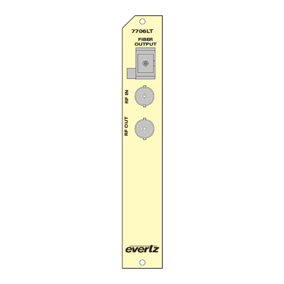
Page 12: 7706Lt Connections
SC/UPC, SC/APC, FC/UPC, FC/APC or ST/UPC female connector with the optical output from the 7706LT. This connector should be connected to the FIBER IN connector of an appropriate Evertz companion receiver model at the destination end with a suitable fiber optic cable. -
Page 13: Assembly
Triangular band: black Symbol: black 2.2.2. Assembly Assembly or repair of the laser sub-module is to be done only at the Evertz facility and performed only by Evertz technical personnel. 2.2.3. Labelling Certification and Identification labels are combined into one label. As there is inadequate space on the product to place the label, it is reproduced here in the manuals. -
Page 14: Handling And Connecting Fibers
Evertz recommends that the user maintain a minimum bending radius of 5 cm to avoid fiber-bending loss that will decrease the maximum attainable distance of the fiber cable. Evertz fiber optic modules are equipped with lockout devices that prevent the user from damaging the fiber connector by installing a module into a slot in the frame that does not have a suitable rear plate installed. -
Page 15: Specifications
7706LT Extended L-Band RF Fiber Transmitter SPECIFICATIONS 3.1. RF INPUT Number of Inputs: Connector: BNC per IEC 61169-8 Annex A (F-Type and SMA Optional) Input Impedance: 75Ω (50Ω Optional) > 15dB (>10dB for 50Ω) Return Loss: Frequency Range: 850MHz-2250MHz Input Power Range: -10dBm to -60dBm AGC Gain Range: -10 to +30dB... -
Page 16: Compliance
7706LT Extended L-Band RF Fiber Transmitter 3.7. COMPLIANCE Laser Safety: Class 1 laser product Complies with 24 CFR 1040.10 and 1040.11 IEC 60825-1 EMI/RFI: Complies with FCC Part 15, Class A EU EMC directive Page - 8 Revision 1.1... -
Page 17: Status Indicators
7706LT Extended L-Band RF Fiber Transmitter STATUS INDICATORS The 7706LT has eight LED status indicators on the front card edge to show operational status of the card at a glance. See Figure 5-1 for LED locations. Two large LEDs on the front of the board indicate the general health of the module: LOCAL FAULT: This red LED will be on during the absence of a valid RF input signal (too low, too high or out of AGC range), an LNB short/overload, or if a local... -
Page 18: Table 4-1: Led Status Indicators
7706LT Extended L-Band RF Fiber Transmitter LED # Colour Function LED 1 is red or LED 2 is off or LED 3 is yellow or LED 4 is red or LED 5 is red. LOCAL / LED 1 is off and LED 2 is green and LED 3 is off and LED 4 is green or off FAULT GREEN and LED 5 is green or off. -
Page 19: Jumper Positions
7706LT Extended L-Band RF Fiber Transmitter JUMPER POSITIONS 5.1. 7706LT JUMPERS AND LEDS Toggle Switch LOCAL FAULT / MODULE OK RF High RF OK RF Low AGC Status LNB Power Status Pushbutton Squelch Status FACTORY FRAME STATUS Serial Upgrade Port Figure 5-1: Location of 7706LT Jumpers and LEDs 5.2. -
Page 20: Configuring The Module For Firmware Upgrades
Upgrading Firmware section of this manual for more information. 5.4. FACTORY AND BDM JUMPERS When shipped from the Evertz facility, the FACTORY and BDM jumpers will not be installed. These jumpers should not be installed for any reason. If jumpers are on these positions they should be removed. -
Page 21: Dot-Matrix Display
7706LT Extended L-Band RF Fiber Transmitter DOT-MATRIX DISPLAY Signal and status monitoring and control of the card’s parameters are provided via the four-digit alphanumeric display located on the card edge. The card-edge toggle-switch (see Figure 5-1) is used to navigate through the display menus and the push button is used to select options. Table 6-1 provides a quick reference to the display menu structure. - Page 22 7706LT Extended L-Band RF Fiber Transmitter Top Level Level 1 Level 2 Level 3 Level 4 BACK BACK 0 to -60 dBm Default -60 dBm RFTH 0 to -60 dBm UPPR Default 0 dBm MODE MAN (default) OFF (default) 0 to -60dBm SQTH Default: -60dBm GAIN...
-
Page 23: Table 6-1: Card Edge Menu Structure
7706LT Extended L-Band RF Fiber Transmitter Fault status (Default) MODE DEFD GAIN CTRL OUTL (continued) LNBV (-LNB only) 22KT (-LNB only) LNBC (-LNB only) HORZ DISP VERT (default) BACK 0 to -60dBm 0 to -60 dBm RFTH UPPR 0 to -60 dBm MODE GAIN (visible in manual... -
Page 24: 7706Lt Controlled Parameters
7706LT Extended L-Band RF Fiber Transmitter 6.1. 7706LT CONTROLLED PARAMETERS To change the 7706LT parameters, select the CTRL menu item in menu level 1. The toggle switch may then be used to select the parameter to change as described below. 6.1.1. -
Page 25: Enabling/Disabling Squelch Mode
7706LT Extended L-Band RF Fiber Transmitter 6.1.3. Enabling/Disabling Squelch Mode Squelch mode will turn off the laser output if the RF input drops below the squelch threshold setting (see section 6.1.4). This feature is useful for triggering downstream automatic main/standby protection switches, and for other such applications. -
Page 26: Adjusting The Agc Target Level
7706LT Extended L-Band RF Fiber Transmitter 6.1.6. Adjusting the AGC Target Level The target output level to be maintained by the 7706LT when AGC mode is user adjustable. Adjustment of this parameter allows optimal laser depth of modulation and CNR performance to be achieved. -
Page 27: Configuring The 22Khz Tone
7706LT Extended L-Band RF Fiber Transmitter 6.1.9. Configuring the 22KHz Tone A 22 kHz tone may be combined with the LNB voltage for universal LNB local oscillator control. The 22KHz tone can be enabled or disabled via the 22KT selection menu. To select the 22KHz tone, select the CTRL menu item in the first menu level, then use the toggle switch to display the 22KT option and press the pushbutton to select it. -
Page 28: Displaying The Rf Threshold
7706LT Extended L-Band RF Fiber Transmitter CTRL Horizontal display used when the module is HORZ DISP housed in the one-rack unit 7701FR frame or the HORZ stand-alone enclosure. VERT Vertical display used when the module is housed VERT in the three-rack unit 7700FR frame. 6.1.13. -
Page 29: Displaying The Laser Status
7706LT Extended L-Band RF Fiber Transmitter 6.1.17. Displaying the Laser Status To display the laser status, select the STAT menu item in the first menu level, then use the toggle switch to display the LASR option and press the pushbutton to select it. STAT LASR Laser is operating normally. -
Page 30: Displaying The Firmware Version
7706LT Extended L-Band RF Fiber Transmitter 6.1.22. Displaying the Firmware Version To display the firmware version, select the STAT menu item in the first menu level, then use the toggle switch to display the VER option and press the pushbutton to select it. The firmware version will scroll across the display.
Need help?
Do you have a question about the 7706LT Series and is the answer not in the manual?
Questions and answers