
Related Manuals for Measurement Computing Switch & Sense 8/8


Summary of Contents for Measurement Computing Switch & Sense 8/8
- Page 1 Switch & Sense 8/8 USB-based Isolated Input and Relay Output User's Guide May 2021. Rev 8 © Measurement Computing Corporation...
- Page 2 Other product and company names mentioned herein are trademarks or trade names of their respective companies. © 2021 Measurement Computing Corporation. All rights reserved. No part of this publication may be reproduced, stored in a retrieval system, or transmitted, in any form by any means, electronic, mechanical, by photocopying, recording, or otherwise without the prior written permission of Measurement Computing Corporation.
-
Page 3: Table Of Contents
Table of Contents Preface About this User's Guide ........................4 What you will learn from this user's guide ..................... 4 Conventions in this user's guide ........................4 Where to find more information ........................4 Chapter 1 Introducing the Switch & Sense 8/8 ....................5 Overview: Switch &... -
Page 4: Preface
Preface About this User's Guide What you will learn from this user's guide This user's guide describes the Measurement Computing Switch & Sense 8/8 data acquisition device and lists device specifications. Conventions in this user's guide For more information Text presented in a box signifies additional information related to the subject matter. -
Page 5: Introducing The Switch & Sense 8/8
Chapter 1 Introducing the Switch & Sense 8/8 Overview: Switch & Sense 8/8 features This user's guide contains all of the information you need to install, configure, and program the Switch & Sense 8/8. The Switch & Sense 8/8 is a USB 1.1 low-speed device used for data acquisition and control. It is designed for USB 1.1 ports, and was tested for full compatibility with both USB 1.1 and USB 2.0 ports. -
Page 6: Functional Block Diagram
Switch & Sense 8/8 User's Guide Introducing the Switch & Sense 8/8 Functional block diagram Switch & Sense 8/8 functions are illustrated in the block diagram shown here. Control Registers Control 9 VDC external Controller power supply (1.5 MBS) Universal Serial Bus HOST Figure 1. -
Page 7: Installing The Switch & Sense 8/8
Chapter 2 Installing the Switch & Sense 8/8 Unpacking As with any electronic device, you should take care while handling to avoid damage from static electricity. Before removing the board from its packaging, ground yourself using a wrist strap or by simply touching the computer chassis or other grounded object to eliminate any stored static charge. -
Page 8: Functional Details
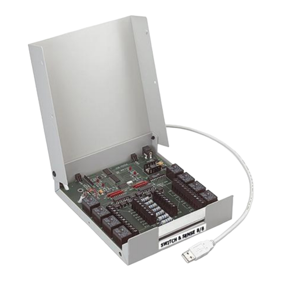
Chapter 3 Functional Details The Switch & Sense 8/8 expands the capabilities of desktop personal computers by providing SPDT relay control and isolated inputs in a plug-and-play package. Screw terminals provide easy field wiring to the three output lines for each of the eight on-board relays. In addition, two terminals are provided for the differential input signals associated with each of the eight isolated inputs. -
Page 9: External Power Led
Switch & Sense 8/8 User's Guide Functional Details External power LED The LED labeled lights up when the Switch & Sense 8/8 is connected to an external EXTERNAL POWER power source. It uses up to 5 mA of current and cannot be disabled. Status LED The LED labeled indicates the communication status of the Switch &... -
Page 10: Main Connector And Pinout
Switch & Sense 8/8 User's Guide Functional Details IP7B IP0A IP7A IP0B IP6B IP1A IP1B IP6A IP5B IP2A IP5A IP2B IP4B IP3A IP4A IP3B Strain Relief for Field Wiring Figure 3. Switch & Sense 8/8 screw terminals and relays Main connector and pinout Connector specifications Connector type Screw terminal... -
Page 11: Relay Contact Terminals (No, C, Nc (0) To No, C, Nc (7))
Switch & Sense 8/8 User's Guide Functional Details Relay contact terminals (NO, C, NC (0) to NO, C, NC (7)) The two outer groups of 12 screw terminals connect to the normally open (NO), common (C), and normally closed (NC) contacts for relays 0 through 7. Form C relay output A schematic for Form C relay contacts is shown here. -
Page 12: Differential Isolated Digital Input Terminals (Ip0A To Ip7B)
Switch & Sense 8/8 User's Guide Functional Details Relay contact protection circuit for inductive loads If you are using the relays to control inductive loads, place a diode across the load terminals to suppress the kickback voltage. If the diode is not present, the kickback voltage could cause the on-board processor to enter an unstable state. - Page 13 Switch & Sense 8/8 User's Guide Functional Details 100K 1.6 K Filter Switch 0.1uF Isolated Input Not Polarized Circuitry Sharing PC Ground Figure 6. Switch & Sense 8/8 single-channel configuration The figure below shows a simple connection from a +9 V battery to the relay 4 terminals. When the relay is energized, the relay 4 NO terminal connects the battery voltage to the input 4 terminal (IP4B).
- Page 14 Switch & Sense 8/8 User's Guide Functional Details Extending the input range You can extend the input range beyond the 5 to 30 V specified by adding an external resistor. Figure 9 shows the external resistor (R The equation R = 100 * (V –...
-
Page 15: Specifications
Chapter 4 Specifications Typical for 25 °C unless otherwise specified. Specifications in italic text are guaranteed by design. USB compliance Device type USB version 1.1 low speed (1.5 Mbs) device Device compatibility USB 1.1, USB 2.0 Power consumption 5 V USB Bus power 20 mA typical , 25 mA max. -
Page 16: Usb Connection
Switch & Sense 8/8 User's Guide Specifications USB connection Captive pigtail cable USB Type A connector Length 2 meters Environmental Operating temperature range 0 to 70 °C Storage temperature range -40 to 100 °C Humidity 0 to 95% non-condensing Mechanical Card dimensions 165 mm long x 150 mm wide x 20 mm high, 6.5 in. - Page 17 Measurement Computing Corporation NI Hungary Kft 10 Commerce Way H-4031 Debrecen, Hátar út 1/A, Hungary Norton, Massachusetts 02766 Phone: +36 (52) 515400 (508) 946-5100 Fax: +36 (52) 515414 Fax: (508) 946-9500 http://hungary.ni.com/debrecen...
Need help?
Do you have a question about the Switch & Sense 8/8 and is the answer not in the manual?
Questions and answers