
Related Manuals for Peak PCAN-PCI Express


Summary of Contents for Peak PCAN-PCI Express
- Page 1 PCAN-PCI Express CAN Interface for PCI Express User Manual Document version 3.4.0 (2015-06-09)
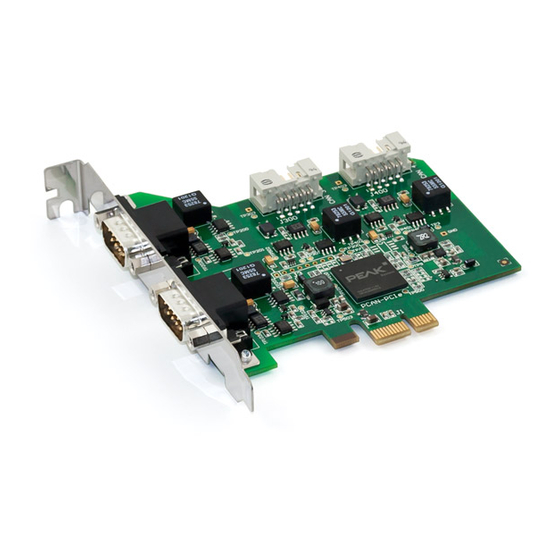
- Page 2 Four CAN channels IPEH-003040 Channel galv. isolated The cover picture shows the product PCAN-PCI Express Four Channel galvanic isolated. Other product versions have an identical form factor but vary in equipment. CANopen® and CiA® are registered community trade marks of CAN in Automation e.v.
-
Page 3: Table Of Contents
PCAN-PCI Express – User Manual Contents Introduction Properties at a Glance System Requirements Scope of Supply Installing the Software and the Card Connecting the CAN Bus D-Sub connector 3.1.1 Slot Bracket with D-Sub Connectors Supplying External Devices via the CAN... - Page 4 PCAN-PCI Express – User Manual Appendix B Dimension Drawing Appendix C Quick Reference...
-
Page 5: Introduction
PCAN-PCI Express – User Manual Introduction The PCAN-PCI Express card enables the connection of a PC with PCI Express slots to CAN networks. There is galvanic isolation of up to 500 Volts between the computer and CAN sides. The card is available as a single, dual, or four-channel version. -
Page 6: System Requirements
Extended operating temperature range from -40 to 85 °C (-40 to 185 °F) Note: This manual describes the use of the PCAN-PCI Express card with Windows. You can find device drivers for Linux and the corresponding application information on the provided DVD in the directory branch Develop and on our website under www.peak-system.com/linux. -
Page 7: Installing The Software And The Card
PCAN-PCI Express – User Manual Installing the Software and the Card This chapter covers the software setup for the PCAN-PCI Express card (short: PCIe card) under Windows and the installation of the card in the computer. Setup the driver before installing the PCIe card. - Page 8 Do the following to install the PCIe card into the computer: Attention! Electrostatic discharge (ESD) can damage or destroy components on the PCAN-PCI Express card. Take precautions to avoid ESD when handling the card. Four-channel version only: Connect the 10-pin connector of CAN ports 3 and 4 with a cable from the slot bracket.
- Page 9 Windows notifies that new hardware has been detected. The drivers are found and installed by Windows. After the initialization process is finished successfully you can find the entry “PCAN-PCI Express” in the branch “CAN-Hardware” of the Windows Device Manager.
-
Page 10: Connecting The Can Bus
CiA® 102. Figure 2: Pin assignment of High-speed CAN connection (view onto a male connector on the PCAN-PCI Express card) With pin 1 devices with low power consumption (e.g. bus conver- ters) can be directly supplied via the CAN connector. At delivery this pin is not assigned. - Page 11 PCAN-PCI Express – User Manual The pin assignment between the D-Sub port and the 10-pin connec- tor on the PCAN-PCI Express Four Channel card for channel 3 and 4 is as follows: Figure 3: Numbering at the 10-pin connector Assignment...
-
Page 12: Slot Bracket With D-Sub Connectors
PCAN-PCI Express – User Manual 3.1.1 Slot Bracket with D-Sub Connectors Figure 4: Dual channel slot bracket Four-channel version only: To connect a CAN bus to the PCAN-PCI Express card, use the supplied slot bracket. After you have con- nected the cables from the slot bracket with the 10-pin sockets of CAN port 3 and 4, you can connect the CAN busses with the D-Sub sockets. -
Page 13: Supplying External Devices Via The Can Connector
Connector A 5-Volt supply can optionally be routed to pin 1 of a D-Sub connec- tor by setting solder bridges on the PCAN-PCI Express card (inde- pendently for each connector on the dual or four-channel version). Thus external devices with low power consumption (e.g. bus converters) can be directly supplied via the CAN connector. - Page 14 PCAN-PCI Express – User Manual Figure 5: Position of the solder fields on the board’s bottom side for a 5-Volt supply at the CAN connection 5-Volt supply → Jumper None Pin 1 CAN 1 JP100 CAN 2 JP200 CAN 3...
-
Page 15: Cabling
Use the card on a terminated CAN bus. 3.3.2 Example of a Connection Figure 6: Simple CAN connection In this example, the PCAN-PCI Express card is connected with a control unit by a cable that is terminated at both ends. -
Page 16: Maximum Bus Length
PCAN-PCI Express – User Manual 3.3.3 Maximum Bus Length High-speed CAN networks may have bit rates of up to 1 Mbit/s. The maximum bus length depends primarily on the bit rate. The following table shows the maximum possible CAN bus length... -
Page 17: Software And Api
PCAN-PCI Express – User Manual Software and API This chapter covers the provided software PCAN-View and the programming interface PCAN-Basic. Monitor Software PCAN-View PCAN-View is simple Windows software for viewing, transmitting, and logging CAN- and CAN FD messages. Note: This chapter describes the use of PCAN-View with a CAN adapter. - Page 18 PCAN-PCI Express – User Manual Do the following to start and initialize PCAN-View: Open the Windows Start menu or the Windows Start page and select PCAN-View. The dialog box for selecting the hardware and for setting the parameters appears. Figure 8: Selection of the hardware and parameters From the list Available PCAN hardware, select the desired interface to be used.
- Page 19 PCAN-PCI Express – User Manual Activate the Listen-only mode if you do not actively participate in the CAN traffic and just want to observe. This also avoids an unintended disruption of an unknown CAN environment (e.g. due to different bit rates).
-
Page 20: Receive/Transmit Tab
PCAN-PCI Express – User Manual 4.1.1 Receive/Transmit Tab Figure 9: Receive/Transmit Tab The Receive/Transmit tab is the main element of PCAN-View. It contains two lists, one for received messages and one for the transmit messages. Representation of CAN data is in hexadecimal format. - Page 21 PCAN-PCI Express – User Manual Figure 10: Dialog box new transmit message Enter the ID and the data for the new CAN message. The field Cycle Time indicates if the message shall be transmitted manually or periodically. If you want to transmit the message periodically, you must enter a value greater than 0.
-
Page 22: Trace Tab
PCAN-PCI Express – User Manual 4.1.2 Trace Tab Figure 11: Trace Tab On the Trace tab the data tracer of PCAN-View is used for logging the communication on a CAN bus. During this process the CAN messages are cached in the working memory of the PC. Afterwards they can be saved to a file. -
Page 23: Pcan-Pci Express Tab
PCAN-PCI Express – User Manual 4.1.3 PCAN-PCI Express Tab Figure 12: PCAN-PCI tab (example) On the PCAN-PCI Express tab various information about your hardware is displayed, like the current device driver version. 4.1.4 Status Bar Figure 13: Display of the Status Bar... -
Page 24: Linking Own Programs With Pcan-Basic
On the provided DVD you can find files of the programming interface PCAN-Basic in the directory branch Develop. This API provides basic functions for linking own programs to CAN- and CAN FD interfaces by PEAK-System and can be used for the following operating systems: Windows 8.1, 7, Vista (32/64-bit) Windows CE 6.x (x86/ARMv4) -
Page 25: Features Of Pcan-Basic
Use of up to 16 channels for each hardware unit (depending on the PEAK CAN interface used) Simple switching between channels of a PEAK CAN interface Driver-internal buffer for 32,768 messages per CAN channel Precision of time stamps on received messages up to 1 μs (depending on the PEAK CAN interface used) Supports PEAK-System‘s trace formats version 1.1 and 2.0 (for... -
Page 26: Principle Description Of The Api
PCAN-PCI Express – User Manual An overview of the API functions is located in the header files. You can find detailed information about the PCAN-Basic API on the provided DVD in the text and help files (file name extensions .txt and .chm). -
Page 27: Notes About The License
Notes about the License Device drivers, the interface DLL, and further files needed for linking are property of the PEAK-System Technik GmbH and may be used only in connection with a hardware component purchased from PEAK-System or one of its partners. If a CAN hardware component... -
Page 28: Technical Specifications
PCAN-PCI Express – User Manual Technical Specifications Connectors Computer PCI Express x1 (1 Lane), Specification 1.1 D-Sub (m), 9 pins Pin assignment according to specification CiA® 102 Specification ISO 11898-2, High-speed CAN 2.0A (standard format) and 2.0B (extended format) Bit rates... - Page 29 PCAN-PCI Express – User Manual Environment Operating temperature -40 - +85 °C Temperature for storage -40 - +125 °C and transport Relative humidity 15 - 90 %, not condensing EN 55024:2011-09 EN 55022:2011-12 EC directive 2004/108/EG...
-
Page 30: Appendix Ace Certificate
PCAN-PCI Express – User Manual Appendix A CE Certificate... -
Page 31: Appendix B Dimension Drawing
PCAN-PCI Express – User Manual Appendix B Dimension Drawing Figure 15: Dimension drawing PCAN-PCI Express The figure does not show the actual size of the product. -
Page 32: Appendix C Quick Reference
PCAN-PCI Express – User Manual Appendix C Quick Reference Software/Hardware Installation under Windows Before installing the PCAN-PCI Express card into the computer set up the corresponding software package from the supplied DVD (with administrator privileges). Afterwards, insert the PCIe card into a vacant PCI Express slot of the switched off computer.
Need help?
Do you have a question about the PCAN-PCI Express and is the answer not in the manual?
Questions and answers