Table of Contents
Advertisement
Quick Links
Advertisement
Table of Contents

Related Manuals for Tech Controllers EU-297 v3


Summary of Contents for Tech Controllers EU-297 v3
- Page 1 EU-297 v3...
-
Page 2: Table Of Contents
TECH CONTENTS Safety ..................................3 Device description ..............................4 III. How to install the controller ............................. 5 Installation of the regulator - batteries ........................6 Installation of the regulator – power supply 230V ....................7 First start-up ................................10 How to use the controller ............................10 Principle of operation ............................ -
Page 3: Safety
EU-297 SAFETY Before using the device for the first time the user should read the following regulations carefully. Not obeying the rules included in this manual may lead to personal injuries or controller damage. The user’s manual should be stored in a safe place for further reference. -
Page 4: Device Description
TECH DEVICE DESCRIPTION The EU-297v3 room regulator is intended for controlling the heating device Its main task is to maintain the pre-set flat/floor temperature by sending a signal to the heating device (contact closing) or the main controller, which controls the actuators, when the room/floor temperature is below the pre-set value. -
Page 5: How To Install The Controller
EU-297 Hardware versions: 1. EU-297 v3 PB, EU-297 v3 PBN – wired version, powered with two AAA 1,5V batteries Colour versions: black or white 2. EU-297 v3 PZ, EU-297 v3 PZN– wired version, powered with 230V Colour versions: black or white III. -
Page 6: Installation Of The Regulator - Batteries
TECH INSTALLATION OF THE REGULATOR - BATTERIES... -
Page 7: Installation Of The Regulator - Power Supply 230V
EU-297 The room regulator should be connected to the heating device with a two-core cable. The cable connection of both devices is shown in the diagram below: heating device NOTE The regulator is powered with batteries - it is recommended to check the batteries from time to time and replace them once every heating season. - Page 8 TECH...
- Page 9 EU-297 The room regulator should be connected to the heating device with a two-core cable. The cable connection of both devices is shown in the diagram below: heating device...
-
Page 10: First Start-Up
TECH IV. FIRST START-UP In order for the EU-297v3 controller to work properly, it is necessary to follow these steps when starting the device for the first time: 1. Insert the batteries - in order to to do it, remove the front cover of the controller (battery version). 2. -
Page 11: Device Description
EU-297 DEVICE DESCRIPTION The user operates the device using touch buttons. 1. Display 2. EXIT button – press this button to display the room temperature/ floor temperature or to disable manual mode. – press this button to decrease the edited value. –... -
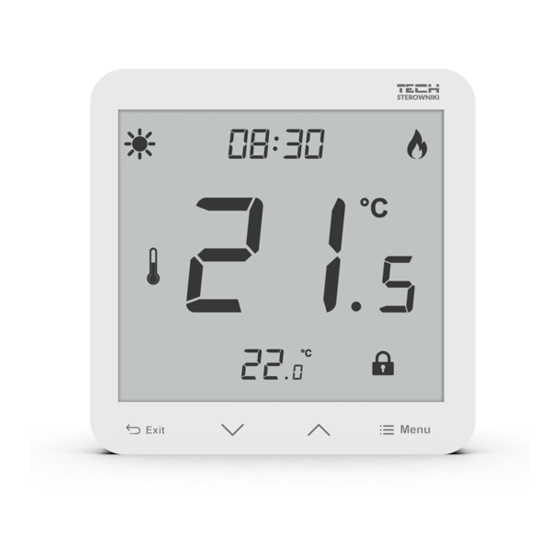
Page 12: Main Screen Description
TECH 1. MAIN SCREEN DESCR IPTION 1. Battery level (battery version) 2. Maximum/minimum floor temperature - this icon is displayed only when the floor sensor is enabled in the controller menu. 3. Hysteresis 4. Night mode 5. Day mode 6. Manual mode 7. -
Page 13: Block Diagram - Main Menu
EU-297 BLOCK DIAGRAM - MAIN MENU Clock Pre-set day temperature Day from... Pre-set night temperature Night from... Hysteresis Maximum temperature Floor heating ON/OFF Minimum temperature Button lock ON/OFF Histeresis 1.1. CLOCK In order to set the time, press MENU button until the clock settings appear on the screen. -
Page 14: Day From
TECH 1.3. DAY FROM… This function enables the user to define the exact time of entering the day mode. To configure this parameter, press MENU until a flashing icon appear on the screen. to set the time of day mode activation. 1.4. -
Page 15: Floor Heating On/Off
EU-297 1.7. FLOOR HEATING ON/OFF This function is used to enable (ON) or disable (OFF) the underfloor heating, with the use of When the underfloor heating is enabled ( ), the user may configure the following parameters: Maximum temperature - in order to set the maximum floor temperature, press MENU until the floor heating icon appears on the screen. -
Page 16: Button Lock On/Off
TECH Minimum floor temperature - 23°C Hysteresis - 2°C When the floor temperature drops to 23°C, the underfloor heating will be enabled. It will be disabled when the temperature reaches 25°C. 1.8. BUTTON LOCK ON/OFF It is possible to activate button lock. In order to do it, press the MENU button until the icon appears on the screen and select ON. -
Page 17: Floor Sensor Calibration
EU-297 2.3. FLOOR SENSOR CALIBRAT ION Floor sensor calibration (an additional icon is displayed: ) should be performed if the floor temperature measured by the sensor differs from the actual temperature. Calibration setting range is from -9,9 to +9,9 ⁰C with the accuracy of 0,1⁰C. To calibrate the built-in sensor, press the MENU button until the floor sensor calibration screen appears. - Page 18 ** DC1 load category: direct current, resistive or slightly inductive load. Hereby, we declare under our sole responsibility that EU-297 v3 manufactured by TECH STEROWNIKI, head-quartered in Wieprz Biała Droga 31, 34-122 Wieprz, is compliant with Directive 2014/35/EU of the European Parliament and of the Council of 26 February 2014 on the harmonisation of the laws of Member States relating to the making available on the market of electrical equipment designed for use within certain voltage limits (EU OJ L 96, of 29.03.2014, p.
- Page 19 EU-297...
- Page 20 TECH...
Need help?
Do you have a question about the EU-297 v3 and is the answer not in the manual?
Questions and answers