Table of Contents
Advertisement
Quick Links
Advertisement
Table of Contents

Related Manuals for Tech Controllers EU-281C


Summary of Contents for Tech Controllers EU-281C
- Page 1 EU-281C...
-
Page 2: Table Of Contents
TABLE OF CONTENTS Safety .................................... 3 Description of the device ............................. 4 III. Installation ..................................5 IV. Module EU-260v1 ................................. 6 How to use the controller ............................7 Principle of operation ............................... 7 Main screen description ............................7 Main screen description - installation screen ..................... 7 Main screen description –... -
Page 3: Safety
SAFETY Before using the device for the first time the user should read the following regulations carefully. Not obeying the rules included in this manual may lead to personal injuries or controller damage. The user’s manual should be stored in a safe place for further reference. -
Page 4: Description Of The Device
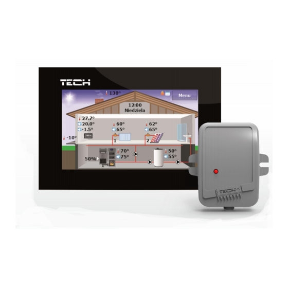
II. DESCRIPTION OF THE DEVICE EU-281C room regulator enables convenient control of the room temperature, CH boiler temperature, water tank temperature as well as the temperature of the mixing valves without the need to go to the boiler room. The regulator may cooperate with various types of main controllers using RS communication: standard controllers, pellet controllers (equipped with an igniter) and installation controllers. -
Page 5: Installation
III. INSTALLATION EU-281C is intended to be flush-mounted. The controller should be installed by a qualified person. WARNING Risk of fatal electric shock from touching live connections. Before working on the controller switch off the power supply and prevent it from being accidentally switched on. -
Page 6: Module Eu-260V1
IV. MODULE EU-260V1 V1 module – intended for . It should be connected to a device with its own power supply. NOTE In order to achieve the maximum aerial sensitivity, EU-260 v1 should be installed at least 50 cm from any metal surface, piping or the CH boiler. -
Page 7: How To Use The Controller
V. HOW TO USE THE CONTROLLER PRINCIPLE OF OPERATI ON The regulator sends a signal to the main controller informing if the pre-set temperature has been reached. Depending on particular settings, reaching the pre-set temperature may result in e.g. CH pump deactivation, pre-defined decrease in the pre-set CH boiler temperature (main controller settings). - Page 8 1. Flue gas temperature (displayed only if a flue gas sensor is used in the main controller). 2. Current time and day of the week - tap here to edit time settings. 3. Icon indicating that alarm clock function is active. 4.
-
Page 9: B) Main Screen Description - Panel Screen
MAIN SCREEN DESCRIPTION – PANEL SCREEN 1. Current operation mode of the pumps. 2. Icon indicating that weekly control function is active. 3. Icon indicating that alarm clock function is active. 4. External temperature (displayed only when the external sensor is used in the main controller). 5. - Page 10 CH boiler temperature panel – Current and pre-set CH boiler temperature – tap on this panel to change the pre-set CH boiler temperature. Water tank temperature panel – Current and pre-set water tank temperature – tap on this panel to change the pre-set water tank temperature.
-
Page 11: Controller Functions - Menu Options
VI. CONTROLLER FUNCTIONS – MENU OPTIONS During standard operation of the controller, graphic display shows the main page. By tapping on MENU the user enters particular settings of the regulator. BLOCK DIAGRAM OF MAI N MENU Clock Time Day of the week Alarm clock Auto-lock Protections... -
Page 12: Time
TIME Tapping on Time icon opens up a panel enabling the user to change clock settings, current day of the week and alarm clock settings. Clock – This function is used to set the current time according to which the regulator operates. ... -
Page 13: Protections
Set the alarm time using ‘up’ and ‘down’ arrows. - If the alarm clock is to be activated on selected days only, the user needs to select the days of alarm clock activation. Screen view when the alarm clock is about to be activated. PROTECTIONS Tap on Protection icon in the main menu to configure parental lock settings. -
Page 14: Screen
PIN code – In order to set PIN code, which is necessary for the user to operate the controller when the lock is activated, tap on PIN icon. NOTE 0000 is the default PIN code. SCREEN Tap on Screen icon in the main menu in order to configure screen settings. ... -
Page 15: Boiler Control
After selecting the day of the week, a panel for setting temperature deviations in selected time intervals is displayed. 1. Decrease temperature 2. Copy temperature deviation to next hours 3. Increase temperature 4. Change time period backwards 5. Change time period forwards 6. -
Page 16: C) Installation Controller Submenu
Operation modes – Tap on this icon to choose one of the following pump operation modes (in the CH boiler controller): House heating, Water tank priority, Parallel pumps or Summer mode. Detailed description of particular operation modes may be found in the CH boiler controller manual. INSTALLATION CONTROLLER SUBMENU ... -
Page 17: Alarms
VII. ALARMS EU-281C room temperature regulator signalizes all alarms which occur in the main controller. In the event of alarm, the room regulator sends a sound signal and the display shows the same message as the main controller. If the internal sensor is damaged, the following alarm appears: ‘Room temperature sensor... - Page 18 EU Declaration of Conformity Hereby, we declare under our sole responsibility that EU-281c manufactured by TECH, head-quartered in Wieprz Biała Droga 31, 34-122 Wieprz, is compliant with Directive 2014/35/EU of the European Parliament and of the Council of 26 February 2014 on the harmonisation of the laws of Member States relating to the making available on the market of electrical equipment designed for use within certain voltage limits (EU OJ L 96, of 29.03.2014, p.
Need help?
Do you have a question about the EU-281C and is the answer not in the manual?
Questions and answers