Advertisement
Quick Links
SERVICE MANUAL
Ver. 1.0 2017.10
Product name
(Model name)
Focal length (mm)
35mm equivalent
focal length*
1
(mm)
Lens groups-elements
Angle of view 1*
Angle of view 2*
Minimum focus*
Maximum magnification (X) 0.31
Minimum aperture
Filter diameter (mm)
Dimensions (maximum
diameter × height)
(approx., mm (in.))
Mass (approx., g (oz))
Shake compensation
function
9-896-828-11
2017J33-1
©
Sony Imaging Products & Solutions Inc.
2017.10
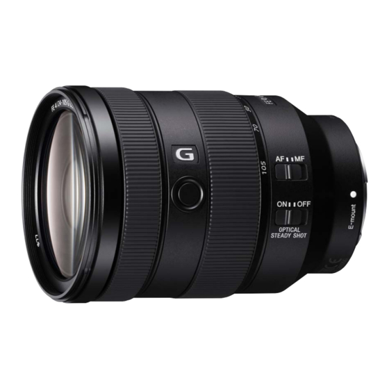
(FE 4/24-105 G OSS) (FE 24-105mm F4 G OSS)
SPECIFICATIONS
FE 24-105mm F4 G OSS
(SEL24105G)
24-105
36-157.5
14-17
2
84°-23°
2
61°-15°
3
(m (feet)) 0.38 (1.25)
f/22
77
83.4 × 113.3
(3 3/8 × 4 1/2)
663 (23.4)
Yes
SEL24105G
This is the equivalent focal length in 35mm format
*
1
when mounted on an Interchangeable Lens Digital
Camera equipped with an APS-C sized image sensor.
Angle of view 1 is the value for 35mm cameras, and
*
2
angle of view 2 is the value for Interchangeable Lens
Digital Cameras equipped with an APS-C sized image
sensor.
Minimum focus is the distance from the image
3
*
sensor to the subject. The minimum focus is 0.41 m
(1.35 feet) at a middle zoom range (around 70 mm).
Depending on the lens mechanism, the focal length
may change with any change in shooting distance.
The focal lengths given above assume the lens is
focused at infinity.
Included items
(The number in parentheses indicates the number
of pieces.)
Lens (1), Front lens cap (1), Rear lens cap (1),
Lens hood (1), Lens case (1), Set of printed
documentation
Design and specifications are subject to change
without notice.
and
are trademarks of Sony Corporation.
INTERCHANGEABLE LENS
US Model
Canadian Model
AEP Model
Chinese Model
E-mount
Advertisement

Related Manuals for Sony FE 24-105mm F4 G OSS


Summary of Contents for Sony FE 24-105mm F4 G OSS
- Page 1 SEL24105G (FE 4/24-105 G OSS) (FE 24-105mm F4 G OSS) SERVICE MANUAL US Model Canadian Model Ver. 1.0 2017.10 AEP Model Chinese Model E-mount SPECIFICATIONS Product name This is the equivalent focal length in 35mm format FE 24-105mm F4 G OSS...
- Page 2 DE FONCTIONNEMENT. NE REMPLACER CES COMPO- • Be sure to control soldering iron tips used for unleaded solder SANTS QUE PAR DES PIÈCES SONY DONT LES NUMÉ- and those for leaded solder so they are managed separately. ROS SONT DONNÉS DANS CE MANUEL OU DANS LES Mixing unleaded solder and leaded solder will cause detach- SUPPLÉMENTS PUBLIÉS PAR SONY.
- Page 3 SEL24105G 1-5. NOTE ON REPLACEMENT OF MAIN BOARD To replace the Main Board (CL-1058 board), connect the E-mount lens to the ILCE-5000, and read/write of the adjustment data in the following procedure. • Before main board replacement “Command” of E-Mount Lens Adjustment (Adjustment Applica- tion for Service) is set to [READ] to implement the [Adjustment Data Backup].
- Page 4 SEL24105G 2. DISASSEMBLY & ASSEMBLY OPERATION NOTES Make sure that the conductive side of a flexible board does not have any stain or foreign materials. Do not touch the conductive side of flexible boards with bare hands. Plug in a flexible board straight, fully into the connector until it reaches the end inside. (Fig. 1, Fig. 2, Fig. 3) (The flexible board was plugged in straight (The flexible board was plugged in (The flexible board was not plugged in...
- Page 5 SEL24105G 2-1. CONSTITUTION DIAGRAM Red arrow direction : Shown the front (lens) side Black arrow direction : Shown the rear (mount) side back adjustment washer 1st moving frame assy 1st group assy cam shading barrel cam follower G_A (5.0_4.5) cam follower G_B filter screw barrel cam pin shaft (M) (5.0_4.5_4.0)
- Page 6 SEL24105G 2-2. DISASSEMBLY • This set can be disassembled in the order shown below. 2-2-1. DISASSEMBLY FLOW FRONT SIDE (LENS SIDE) REAR SIDE (MOUNT SIDE) 2-2-2. FRONT RING 2-2-5. ZOOM RING RUBBER (Page 2-4) (Page 2-5) 2-2-3. FILTER SCREW BARREL OPTICAL AXIS ADJUSTMENT (Page 2-4) RESOLVING POWER...
- Page 7 SEL24105G Note: Follow the disassembly procedure in the numerical order given. 2-2-2. FRONT RING 1 Rotate the front ring in the direction of the arrow, and remove it. front (lens) side rear (mount) side 2-2-3. FILTER SCREW BARREL 1 six tapping screws (BTITE (1.4 2 filter screw barrel front (lens) side rear (mount) side...
- Page 8 SEL24105G 2-2-4. 1ST GROUP ASSY 1 three tapping screws (TP1.7 2 1st group assy 3 three back adjustment washers Note: Take note of the amount of back adjustment washers . front (lens) side rear (mount) side 2-2-5. ZOOM RING RUBBER 1 zoom ring rubber 2 guard tape Z rear (mount) side...
- Page 9 SEL24105G 2-2-6. MOUNT ASSY rear shading barrel 1 four screws (TP2 tapping screw (TP1.4 rear (mount) side tapping screw mount block (TP1.4 4 mount assy front (lens) side tapping screw 3 BL contact flexible board (TP1.4 tapping screw (TP1.4 BL contact assy 2 Lift up the mount assy.
- Page 10 SEL24105G 2-2-7. CL-1058 BOARD BLOCK 4 CL-1058 board block rubber bush A (total eight pieces) rubber bush A rubber bush A board spacer 1 Lift up the CL-1058 board block after CL-1058 board removing eight rubber bush A from rubber bush A eight places of bosses.
- Page 11 SEL24105G 2-2-9. APPEARANCE ASSY hole hole 2 zoom linkage pin 2 zoom linkage pin rear (mount) side 1 Rotate the zoom ring assy, and align the hole of the zoom ring assy with the zoom linkage pin. 3 Peel off the MP cushion front (lens) side 5 Remove the flexible board.
- Page 12 SEL24105G 2-2-10. ZOOM RING ASSY rear (mount) side front (lens) side hole 1 Rotate the zoom ring assy in the direction of the arrow, align the hole of the zoom ring assy with the position shown in the figure. 2 zoom ring assy 3 ESD gasket groove slider...
- Page 13 SEL24105G 2-2-11. FOCUS RING RUBBER rear (mount) side front (lens) side 2 guard tape F 1 focus ring rubber 2-2-12. FOCUS RING rear (mount) side 2 screw (B1.4 front (lens) side 3 focus ring key 2 screw (B1.4 3 focus ring key 1 Rotate the focus ring, and align the hole of the focus ring with the focus ring key.
- Page 14 SEL24105G 2-2-13. OUTER BLOCK ASSY 1 SP cushion 1 SP cushion 3 tapping screw (P1.4 2.5) rear (mount) side 1 SP cushion front (lens) side 3 tapping screw (P1.4 2.5) 3 tapping screw (P1.4 2.5) 1 SP cushion 2 ESD gasket 5 outer block assy 4 three claws outer barrel assy...
- Page 15 SEL24105G 2-2-14. ZMR ASSY 1 two screws (M1.7 3.5) 2 ZMR assy rear (mount) side front (lens) side 2-12...
- Page 16 SEL24105G 2-2-15. 1ST MOVING FRAME ASSY 1 cam pin A 1 cam pin A 1 cam pin A rear (mount) side front (lens) side 3 cam pin shaft (M) 3 cam pin shaft (M) 3 cam pin shaft (M) 4 three cam followers G_A (5.0_4.5) 2 1st moving frame assy 2-13...
- Page 17 SEL24105G 2-2-16. 3-5TH GROUP BLOCK 1 two screws (M1.7 2.5 torasuta (CH)) 3 cam pin G_B 4 three cam followers G_B (5.0_4.5_4.0) 2 main FPC plate 3 cam pin G_B 3 cam pin G_B rear (mount) side front (lens) side G17 mask block assy 5 3-5th group block rear (mount) side...
- Page 18 SEL24105G 2-2-17. 2ND LENS BARREL ASSY 2 Remove by rotating the cam shading barrel in the direction of the arrow. 3 cam pin G_B 1 adhesive bond front (lens) side 3 cam pin G_B rear (mount) side 4 three cam followers G_B (5.0_4.5_4.0) 3 cam pin G_B 5 2nd lens barrel assy 2-15...
- Page 19 SEL24105G 2-3. ASSEMBLY • This set can be assembled in the order shown below. 2-3-1. ASSEMBLY FLOW CAM BARREL ASSY OUTER BARREL ASSY 2-3-2. 2ND LENS BARREL ASSY 2-3-6. OUTER BLOCK ASSY (Page 2-17) (Page 2-21) 2-3-3. 3-5TH GROUP BLOCK 2-3-7.
- Page 20 SEL24105G Note: Follow the assembly procedure in the numerical order given. 2-3-2. 2ND LENS BARREL ASSY 3 Align the marking of the 2nd lens barrel assy with ditch, and install the 2nd lens barrel assy. marking cam barrel assy front (lens) side 1 Rotate the zoom cam barrel in the direction of the arrow.
- Page 21 SEL24105G 2-3-3. 3-5TH GROUP BLOCK 6 Align the marking of the 3-5th group block with ditch, and install the 3-5th group block. 1 3-5th group assy rear (mount) side front (lens) side marking ditch 5 Align the position of ditches. 2 Make valley fold on the flexible board.
- Page 22 SEL24105G 2-3-4. 1ST MOVING FRAME ASSY 4 cam pin shaft (M) 2 Align the position of ditches. Note 2: Install the cam pin shaft (M) as shown in the direction of figure. rear (mount) side 4 cam pin shaft (M) front (lens) side 4 cam pin shaft (M) 1 Rotate the zoom cam barrel in...
- Page 23 SEL24105G 2-3-5. ZMR ASSY 3 two screws (M1.7 3.5) 1 ZMR assy 2 two bosses rear (mount) side front (lens) side 2-20...
- Page 24 SEL24105G 2-3-6. OUTER BLOCK ASSY 1 Align the FH button with switch, and install the outer block assy. FH button 2 three claws outer barrel assy rear (mount) side guide line 5 SP cushion front (lens) side switch 6 Apply grease. G-85 guide line 5 SP cushion...
- Page 25 SEL24105G 2-3-7. FOCUS RING 2 Apply grease. (total four position) G-85 Note: Grease must not attach to this part. rear (mount) side front (lens) side rear (mount) side front (lens) side potentiometer Note: Grease must not 1 Apply grease. attach to this part. (total two position) G-115 Note: Grease must not attach to this part.
- Page 26 SEL24105G 2-3-8. FOCUS RING KEY 4 Rotate the focus ring a little in the direction of the arrow. focus ring key rear (mount) side front (lens) side 5 Apply grease. focus ring key 5 Apply grease. (total two position) 3 screw (B1.4 (total one position) G-85 G-85...
- Page 27 SEL24105G 2-3-10. ZOOM RING ASSY 3 Align the hole of the zoom ring assy with slider, and install the zoom ring assy. 1 ESD gasket groove hole center rear (mount) side 2 Match the slider with the position shown in the figure. front (lens) side slider 4 Rotate the zoom ring assy in the direction of the arrow.
- Page 28 SEL24105G 2-3-11. APPEARANCE ASSY 4 six screws (M1.7 Note 3: Apply the adhesive bond to the tip of screws. B-40 3 appearance assy Note 1: Take care not to damage the flexible board. Note 2: When installing the appearance assy assy, be careful not to turn over the gasket.
- Page 29 SEL24105G 2-3-12. ZOOM LINKAGE PIN screw hole screw hole hole hole 2 zoom linkage pin 2 zoom linkage pin rear (mount) side front (lens) side 1 Rotate the zoom ring assy, and align the hole of the zoom ring assy with the screw hole.
- Page 30 SEL24105G 2-3-14. REAR BARREL ASSY Note 1: Be careful of the direction of installation. rear (mount) side front (lens) side ditch 2 mount rubber rear (mount) side front (lens) side 1 rear barrel assy 5 three tapping screws (TP1.7 3 Align two switching levers with two ditches, and install the rear barrel block.
- Page 31 SEL24105G 2-3-15. CL-1058 BOARD 2 rubber bush A Note: Be careful of the direction of installation. 2 rubber bush A 3 board spacer long (rear (mount) side) short (front (lens) side) rubber bush A 1 CL-1058 board 2 rubber bush A rear (mount) side 2 two rubber bushs A 2 rubber bush A...
- Page 32 SEL24105G 2-3-17. BL CONTACT ASSY 5 rear shading barrel rear (mount) side front (lens) side 6 tapping screw (TP1.4 1 mount block 6 tapping screw (TP1.4 7 conductive tape 4 tapping screw mount assy (TP1.4 (from front (lens) side) 6 tapping screw (TP1.4 8 Crease the BL contact flexible board.
- Page 33 SEL24105G 2-3-19. ZOOM RING RUBBER 2 zoom ring rubber Note 1: Be careful of the direction of installation. rear (mount) side front (lens) side 1 guard tape Z rear (mount) side pasting reference front (lens) side guard tape Z Note 2: The edge of the guard tape Z does not come over the hole.
- Page 34 SEL24105G 2-3-21. FILTER SCREW BARREL filter screw barrel 2 six tapping screws (BTITE (1.4 (from front (lens) side) 1 Align the square rib with the boss, square rib and install the filter screw barrel. boss front (lens) side Note: When installing the filter screw barrel, be careful not to catch the gasket.
- Page 35 SEL24105G 3. EXPLODED VIEWS Note: • -XX and -X mean standardized parts, so they may have some difference from the original one. • Items marked “*” are not stocked since they are seldom required for routine service. Some delay should be anticipated when ordering these items.
- Page 36 SEL24105G 3-2. MOUNT SECTION Red arrow direction : Shown the front (lens) side Black arrow direction : Shown the rear (mount) side Refer to cam barrel section Refer to outer barrel section (Note) (Note) not supplied (Note) (Note) not supplied not supplied not supplied Note: This part is for resolving power adjustment.
- Page 37 SEL24105G 3-3. OUTER BARREL SECTION Red arrow direction : Shown the front (lens) side Black arrow direction : Shown the rear (mount) side 107 114 Ref. No. Part No. Description Ref. No. Part No. Description 4-690-158-01 ZOOM RING RUBBER (9121) 4-441-121-11 ESD GASKET 4-693-030-01...
- Page 38 SEL24105G 3-4. CAM BARREL SECTION Red arrow direction : Shown the front (lens) side Black arrow direction : Shown the rear (mount) side (Note) (Note) (Note) (Note) (Note) (Note) (Note) (Note) (Note) Note: Selection of this part is required for each unit. Perform an opera- tion check of the relevant locations, refer to “3-5.
- Page 39 SEL24105G 3-5. SELECTION PARTS Ref. No. 6 BACK ADJUSTMENT WASHER Ref. No. 158 CAM FOLLOWER G_A (5.0_4.5) (for resolving power adjustment) Perform an operation check of the relevant locations, and select an This part is for resolving power adjustment. appropriate part. Adjust the thickness by following the results of the resolving power check.
- Page 40 SEL24105G 4. SUPPLIED ACCESSORIES Note: • Items marked “*” are not stocked since they are seldom required for routine service. Some delay should be anticipated when ordering these items. Ref. No. Part No. Description 4-695-033-01 MANUAL, INSTRUCTION (JAPANESE, ENGLISH, FRENCH, SPANISH, SIMPLIFIED CHINESE) 4-695-033-11 MANUAL, INSTRUCTION (GERMAN, DUTCH, SWEDISH, ITALIAN, PORTUGUESE)
- Page 41 SEL24105G 5. ADJUSTMENTS Note: When disassembled the lens, after the assembly has been completed, perform adjustments by referring to this chapter. 5-1. BEFORE STARTING ADJUSTMENTS 5-1-1. Adjustment Items after Replacing Parts When replacing main parts and boards, adjust or check the items indicated by z in the following table. Note: Do not adjust the items indicated by .
- Page 42 SEL24105G 5-1-2. Adjustment/Check Procedure Flow Chart After the parts replacement 5-2-3. Optical axis adjustment Perform the Replace the 3-5th group adjustment, it does not 5-2-2. Optical axis improve the assy check symptoms. Resolving power adj. Replace the 1st group assy (Note 2) Perform the 5-3.
- Page 43 SEL24105G 5-1-3. List of Service Tools and Equipment Service Tools/Equipments Part No. Fig. No. Remarks E-Mount_Lens_Adjustment_(E).zip (Adjustment Application for Service) Version: 1.4.3.0 or higher Lens adjustment program ― ― Following two files are stored in “C:\FSA\VX9121” folder of the C E-Mount Lens Adjustment drive.
- Page 44 SEL24105G Service Tools/Equipments Part No. Fig. No. Remarks 1-487-963-12 Except US, Canadian AC adaptor (AC-PW20) 1-487-963-22 US, Canadian Flange back adjustment jig J-6082-563-A FB adjustment chart (10 mm) J-6082-819-A For “Flange Back Adjustment”. J-6082-604-A 110V 1000 mm Collimator J-6082-604-B 240V Flange back tester J-6082-606-A FB tester stand...
- Page 45 SEL24105G 5-2. OPTICAL AXIS CHECK/ Setting of the Flange Back Tester 1. Set the equipment as shown in the following figure. ADJUSTMENT Dial Gauge A-mount attachment (Min. scale: 0.01 mm) 5-2-1. Setting/Preparation of the Flange Back (f’F) Objective lens (10x) Measuring Instrument Eyepiece lens (7x) Equipment and Tools (Common)
- Page 46 SEL24105G Preparations of Using a Camera (General E-mount Preparations of Using a B-L Control Box Interchangeable Lens Digital Camera) Equipment and Tools • Personal Computer (See Note 1) Equipment and Tools • B-L Control Box (Supplied with D-sub 15-pin cable) •...
- Page 47 SEL24105G 5. When starting and finishing the BLG-TestProgram, perform the following procedure. • Starting the BLG-TestProgram • Finishing the BLG-TestProgram Procedure of Starting Procedure of Finishing (1) Mount a lens to be tested to the lens mount block. (1) Click [Power] to turn off the power to the lens. (2) Connect the D-sub 15-pin cable to the lens mount block, and (2) Confirm that the two LEDs on the B-L Control Box are not lit.
- Page 48 SEL24105G 6. Start the lens adjustment program “BLG-TestProgramV[][][].exe”. 7. When [Open] is clicked and communication between personal computer and B-L Control Box is connected, the button name changes to [Close] and the [Power] button is made active. 8. Click [Power] to supply power to the lens to be tested. At this time, confirm that both of the two LEDs on the B-L Control Box are light.
- Page 49 SEL24105G 10. Align the plane mirror with the center projected image on the screen, and confirm again that the reflected light illuminates the center of the lens to be tested. If the reflected light position is deviated, re-adjust the lens projector position. 11.
- Page 50 SEL24105G 5-2-2. Optical Axis Check 5-2-3. Optical Axis Adjustment Note: Optical Axis Adjustment is done by moving the 3th group assy Checking Procedure in the 3-5th group assy. 1. Adjust the optical axis while observing the microscope until the Refer to “2-2. DISASSEMBLY”, disassemble the lens, and chart image can be seen in the center.
- Page 51 SEL24105G 5-3. RESOLVING POWER CHECK 5-3-1. Setting/Preparation of the Lens Test Projector Preparations of Using a Camera (General E-mount Interchangeable Lens Digital Camera) Equipment and Tools • Camera (General E-mount interchangeable lens digital camera) • Lens Test Projector (F) • E-mount FF jig for Lens Test Projector (F) (See Note) •...
- Page 52 SEL24105G Preparations of Using a B-L Control Box Equipment and Tools • Personal Computer (See Note 1) • B-L Control Box (Supplied with D-sub 15-pin cable) • AC cable (Sold on the market) • RS-232C Cable (D-sub 9-pin (Male with securing screws), D-sub 9-pin (Female with securing screws)) Straight type (Sold on the market) •...
- Page 53 SEL24105G (2) Starting and Finishing the BLG-TestProgram Starting the BLG-TestProgram Procedure of Finishing 1. Mount a lens to be tested to the lens mount block. 1. Click [Power] to turn off the power to the lens. 2. Connect the D-sub 15-pin cable to the lens mount block, and 2.
- Page 54 SEL24105G (3) Setting Method Setting Procedure 1. Start the lens adjustment program “BLG-TestProgramV[][][].exe”. 2. When [Open] is clicked and communication between personal computer and B-L Control Box is connected, the button name changes to [Close] and the [Power] button is made active. 3.
- Page 55 SEL24105G 5. Align the plane mirror with the center projected image on the screen, and confirm again that the reflected light illuminates the center of the lens to be tested. If the reflected light position is deviated, re-adjust the lens projector position. 6.
- Page 56 SEL24105G 9. Clicking [Focus(Target Dist.)] displays the focus JOG operation window. Focus position indicator Select focus step value Select and enter focus step speed Focus drive Focus drive (near) (far) 10. Adjust the focus position with [Near] and [Far] while selecting “Focus Step” and “Low”/“Mid”/“High”, and then click [OK] to close the focus JOG window.
- Page 57 SEL24105G 5-3-2. Projective Resolving Power Check Reference value: Number of projective resolving power lines (lines/mm) Focal length f Distance (m) (mm) Peripheral (y' = 15) Peripheral (y' = 18) Center (y' = 0) 0.96 More than More than More than More than More than 63 lines...
- Page 58 SEL24105G 4. Read the value of the number of projective resolving power lines (maximum resolving power) of the center projected image (y’ = 0). 5. Read the value (the number of projective resolving power lines) of the thinnest line (resolution limit) that allows recognition of contrast of the sagittal (S) image and meridional (M) image (three lines) of the peripheral projected image (y’...
- Page 59 SEL24105G 5-3-3. Photographic Resolving Power Check For this lens, it is necessary to check the photographic resolving power with two kinds of focal length (24 mm, 105 mm). Therefore, please check with the case where the zoom set to the WIDE end (focal length: 24 mm) and the case where it is set to the TELE end (focal length: 105 mm).
- Page 60 SEL24105G 5-4. RESOLVING POWER ADJUSTMENT Note: Resolving Power Adjustment is done by increasing or decreas- ing the thickness of the washer. Refer to “2-2. DISASSEMBLY”, disassemble the lens, and change the thickness of the washer. 5-4-1. Partial Blur (TELE side) Adjustment Adjusting Procedure 1.
- Page 61 SEL24105G 5-4-2. Partial Blur (WIDE side)/Curvature Adjustment Adjusting Procedure ADJUSTMENT SHIM 1. Increase or decrease the thickness of the adjustment shim to adjust the partial blur/curvature. Partial blur: Set the zoom to the WIDE end, Change the thick- ness of the side where blurring occurs. Curvature: Change the thickness of the whole.
- Page 62 SEL24105G 5-5. E-MOUNT LENS ADJUSTMENT (1) Installation For adjustment of the SEL24105G, prepare a version 1.4.3.0 or higher of the lens adjustment program (E-Mount Lens Adjustment.zip). Equipment and Tools • Personal Computer (See Note 1, 2) Note: Perform the installation by administrator privileges. •...
- Page 63 SEL24105G 5. The installer start up screen appears, then click the [Next] button 5-5-2. Precautions for Use to start the installation. • When the instruction “PUSH ENTER” as shown below is displayed on the screen, if the “PUSH ENTER” does not disappear even after pressing the ENTER key, press it again.
- Page 64 SEL24105G 5-5-3. Method of Starting and Finishing 5-5-4. Adjustment Method of Each Item (1) Starting the E-Mount Lens Adjustment (1) Lens Device (S) Make sure to disconnect the AC adaptor after finishing the adjustment • Adjust and inspection the focusing ring. (including the case when stops due to an error).
- Page 65 SEL24105G 7. “MF ROTATION STOP” is displayed, press the ENTER key. (2) Lens Device2 (S) • Adjust the MR sensor of focus and zoom. • Adjust the mechanical end of focus and zoom. • Adjust the frequency of focus PWM. •...
- Page 66 SEL24105G 5. When the ENTER key is pressed, message screen is displayed 9. When the ENTER key is pressed, message screen is displayed in the following. Set the zooming ring to the TELE end (focal in the following. Set the zooming ring to the TELE end (focal length: 105 mm).
- Page 67 SEL24105G (3) Lens Device3 (S) 4. The message screen is displayed in the following order. Operate the shake compensation switch accordance with the message. • Check the switch operation. Subject Not required • Focus hold button Operation on Lens side •...
- Page 68 SEL24105G (4) Steady Hall (S) (5) Flange Back (S) • Adjust the position detection hall element for shake compensation. • Adjust the flange back of inner focus lens. Subject Not required Flange back adjustment jig Subject + FB adjustment chart Operation on Lens side Not required Operation on Lens side...
- Page 69 SEL24105G 5. After the automatic adjustment of WIDE end is completed, mes- 8. Rotate the zooming ring to the TELE side until the background sage screen is displayed in the following. Set the zooming ring color of the value (hexadecimal number) at the lower left of the to the TELE end (focal length: 105 mm).
- Page 70 SEL24105G 13. Rotate the zooming ring to the WIDE side until the background (6) F Number (S) color of the value (hexadecimal number) at the lower left of the • Perform focus actuator inspection. window changes to light blue. • Perform actuator damage inspection. •...
- Page 71 SEL24105G (7) Focus Shift Adjustment 3. “Set FocusSW : AF” is displayed, set the focus mode switch to the AF. • The focus shift due to change in the F number is corrected. • Flange back adjustment jig Subject + FB adjustment chart •...
- Page 72 SEL24105G 8. When the ENTER key is pressed, automatic adjustment is started. 15. After the automatic adjustment is completed, message screen is 9. After the automatic adjustment is completed, message screen is displayed in the following. Set the zooming ring to the TELE displayed in the following.
- Page 73 SEL24105G 20. After the automatic adjustment is completed, the calculation (8) Lens Sleep processing of the quantity of correction is started. The display • Set the switch to initial position. of the message screen changes as follows. • Set the lens to the sleep mode. (Processing time: 10 to 15 minutes) Subject Not required...
- Page 74 SEL24105G Revision History Ver. Date History Contents 2017.10 Official Release —...
Need help?
Do you have a question about the FE 24-105mm F4 G OSS and is the answer not in the manual?
Questions and answers