Table of Contents
Advertisement
Advertisement
Table of Contents
Troubleshooting

Subscribe to Our Youtube Channel
Related Manuals for DENTSPLY ProMix 400


Summary of Contents for DENTSPLY ProMix 400
- Page 1 REPAIR GUIDE MODEL 400 MODEL 401 MODEL 402 ProMix AMALGAMATION UNIT...
-
Page 3: Table Of Contents
TABLE OF CONTENTS SECTION TITLE PAGE SECTION I: TECHNICAL DETAILS & SPECIFICATIONS TECHNICAL DETAILS ................OPERATING ENVIRONMENT ..............DIMENSIONS .................... SECTION II: GLOSSARY OF SYMBOLS GLOSSARY OF SYMBOLS ..............SECTION III: SAFETY PRECAUTIONS SAFETY PRECAUTIONS ................ SECTION IV: GENERAL DESCRIPTION INTRODUCTION .................. -
Page 4: Section I: Technical Details & Specifications
SECTION I TECHNICAL DETAILS & SPECIFICATIONS Technical Details: AC INPUT RATING: Model 400 120V, 60Hz, 2.0A Model 401 230V, 50/60Hz, 1.0A FUSE RATING: Model 400 F2.0A /250V Model 401 F1.6A/250V MOTOR RATING: 115VAC, 60Hz PRESET MOTOR SPEEDS: Low (Turtle) 3700±200 rpm High (Rabbit) 4200±200 rpm IEC EQUIPMENT CLASS:... -
Page 5: Glossary Of Symbols
SECTION II GLOSSARY OF SYMBOLS ______ Attention, Consult Accompanying Documents ______ Alternating Current ______ Protective Earth ______ OFF (Power: Disconnection from the Mains) ______ ON (Power: Connection to the Mains) -
Page 6: Safety Precautions
3. Should the ProMix ™ get damaged in any way, do not attempt to operate the unit unless thoroughly inspected and serviced by qualified Dentsply Dealer Service personnel. 4. In cases where a patient or user of the ProMix ™ has been fitted with an implanted heart pacemaker and has been cautioned against the use of small electrical appliances (such as electric shavers, hair dryers, etc.) we recommend that the... -
Page 7: Section Iv: General Description
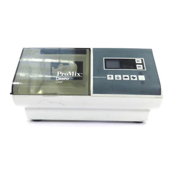
SECTION IV GENERAL DESCRIPTION The microprocessor controlled ProMix ™ is one of the most advanced amalgam mixer systems presently available in the dental marketplace. ™ The ProMix Amalgamation Unit provides: a) Two Preset Speeds with an LED indicating the Low speed (3700 rpm) and an LED indicating the High speed (4200 rpm). -
Page 8: Installation
INSTALLATION NOTE: Upon receiving the ProMix™ system check the packaging and parts for any damage that may have occurred in transit. If damage is apparent, please contact your dealer immediately. Unit Power-up (Initialization): Plug the detachable power cord into the back of the unit and then to the mains supply. NOTE: Always use the unit in conjunction with a properly grounded outlet. -
Page 9: Operation
OPERATION The operation of the ProMix™ can be controlled by the LCD display and the seven (7) push buttons/pads located on the front panel. Display Board Indicates the set (desired) amalgamation cycle/run time and counts down to “00” in 1 second intervals during operation. -
Page 10: Section Vi: Service And Maintenance
SECTION VI SERVICE AND MAINTENANCE SERVICE Questions concerning the operation, repair or servicing of this unit should be forwarded to the nearest Dentsply representative or the service department. CLEANING NOTE: Disconnect the power cord from the ProMix™ unit prior to cleaning. -
Page 11: Electrical Trouble Shooting
7.2.1 Display Board does not come on when main switch at the back of the unit is turned on. Possible Problem Solution A. Loose Lead Wires Open unit and check for loose lead wire connections between the A/C receptacle, main power switch Fig (1a), and the power supply. - Page 12 C. Power Supply Locate CPU Board (Fig 1d) and disconnect connector J1 (Fig 1d). Locate power supply (Fig 1c). Measure voltage between the wire connection marked ac- and ground marked gnd (See Fig 1c). This voltage should be greater than 7V a.c..
- Page 13 7.2.2 Display Board activates but switches are inactive. Possible Causes Solutions A. Power Supply See para 7.2.1 C B. C.P.U. Board See para 7.2.1.D C. Display Board If 7.2.2. A and B fail to correct problem replace Display Board (Fig 1f) 7.2.3 Display Board Up(’) / Down(‘) keys operate properly, but on/off key activation does not start the unit.
- Page 14 B. Door switch cable connections Locate CPU board (Fig 1d). Check for loose or (Model 401, 402, 230v) open connections to J2 (Fig 3b). If loose in connections, press wires into connector to insure good contact. If the problem persists, replace door switch cable assembly.
- Page 15 7.2.4 Motor speeds up and stops immediately after turned on, All other keys function properly. Possible Problem Solution A. Optical detector board assembly Locate optical detector board (Fig 4a). Check for broken wires in cable to power supply. If broken or intermittent, replace optical detector board assembly.
- Page 16 7.2.5 Motor speed is inconsistent. Possible Problem Solution A. Loose wires Locate power supply (Fig 1c). Check for loose or broken capacitor/ resistor connections in cable assembly (Fig 5a). If broken, replace assembly. B. Optical Detector Refer to 7.2.4. B C.
-
Page 17: Mechanical Trouble Shooting
MECHANICAL FAILURES 7.3.1 Capsule remains locked in arm. Possible Problem Solution A. Arm release Locate the arm release mechanism Fig 5b. and press A and B together repeatedly in the direction of the arrows. 7.3.2 Unit moves from vibration during operation. Possible Problem Solution A. - Page 18 7.3.4 Arm opens and does not hold capsule. Possible Cause Solution A Broken arm Replace arm assembly (Fig 6c). See assembly/disassembly. 7.3.5 Rubber boot falls off. Possible Cause Solution A. Glue bond is broken Glue the boot back to plastic using Loctite Super bonder 498 (Fig 8.2).
-
Page 19: Promix Disassembly
Assembly and disassembly procedure (CAUTION: DISCONNECT POWER SOURCE FROM UNIT BEFORE ATTEMPTING ANY DISASSEMBLY OR REPAIR PROCEDURE) ProMix™ Disassembly a. Turn the unit upside down and completely loosen the 4 screws in the bottom half of the enclosure. (As shown in the Fig 8.1). b. - Page 20 8.1.2 Power Supply Removal. Model 400 a. 120v power supply removal. Disconect cable connection to CPU board at 120 Volt J1 and J3 (Fig 1d) Disconnect optical Detector board and door switch connections at power supply board J2 and J3 (Fig 3a). Model 401, a.
- Page 21 8.1.5 Tail Spring Assembly & Disassembly. a. Cut the tail spring in the centre using a pair of wire cutters (Fig 8.5). b. Remove the spring by unhooking from the arm assembly. c. To replace the spring hook onto the arm first. 8.1.6 Arm Assembly &...
-
Page 22: Component List
COMPONENT LIST (Promix) Model Dependent Components: Model 400 Model 401 Model 402 Component Description Part No. Part No. Part No. CPU Board PM400001 PM401001 PM401001 Power Supply PM400002 PM401002 PM401002 Optical Detector Board PM400003 PM401003 PM401003 Door Switch Cable Assembly PM400004 PM401004 PM401004... - Page 23 NOTES...
- Page 24 In the USA In Europe Dentsply Caulk Dentsply DeTrey-DeDent Dentsply International Inc. D-7750 Konstanz Milford, De 19963-0359 Germany 78404 Printed in Canada (2/95)
Need help?
Do you have a question about the ProMix 400 and is the answer not in the manual?
Questions and answers