
Related Manuals for DENTSPLY Midwest E Electric Handpiece System


Summary of Contents for DENTSPLY Midwest E Electric Handpiece System
- Page 1 Directions for Use CAUTION: US Federal law restricts this device to sale by or on the order of a licensed dental professional Doc. No. 87514-0914...
-
Page 2: Table Of Contents
General Operation ............19 Operational Mode Options ..........20 7 Preparation Mode ............21 All trademarks referred to are the property of their respective owners. Manufactured for: DENTSPLY Professional A division of DENTSPLY International 901 West Oakton Street Des Plaines, IL 60018-1843 www.dentsply.com... -
Page 3: Introduction
1 Introduction Introduction ® The Midwest E Electric Handpiece System is a dental handpiece system with various attachments, intended for cutting, shaping, filing, drilling, cleaning and polishing procedures in both general and endodontic dentistry. System Contents ® The Midwest E Electric Handpiece System is comprised of the following components: ... -
Page 4: Important Information
2 Important Information Important Information Indications for Use ® The Midwest E Electric Handpiece System is intended for use by dental professionals in the performance of dental restoration, prophylaxis and endodontic procedures. Attachments are offered to complement the system used for general dentistry work. The intended use of the respective attachment is dependent on the gear ratio. - Page 5 Service Using Authorized Personnel Only Supply of spare parts, service, and maintenance of the Midwest® E Electric Handpiece System is restricted to DENTSPLY authorized service personnel only. Use of other servicing or non-qualified parts is prohibited. NOTE: Send the product every 3 years for a service check. The safety check according to IEC 62353 and the measurement check will be carried out during service check.
-
Page 6: Precautions
2 Important Information Handpiece Attachments Follow and adhere all instructions described in the Handpiece Attachment Directions for Use. Ensure Handpiece Attachments are inserted completely, such that the attachment and motor are flush with each other. Follow the separate User Manual for attaching and using the dental attachments. -
Page 7: Applied Symbols
Supply of spare parts, service and maintenance may only be carried out by authorized personnel. DENTSPLY shall assume no liability for accidental, special or consequential damage caused by maintenance or service of the Midwest E unit by third parties, or for use of equipment or parts manufactured by third parties, including loss of profit, any commercial loss, economic loss or loss incurred by personal injury. -
Page 8: Product Overview
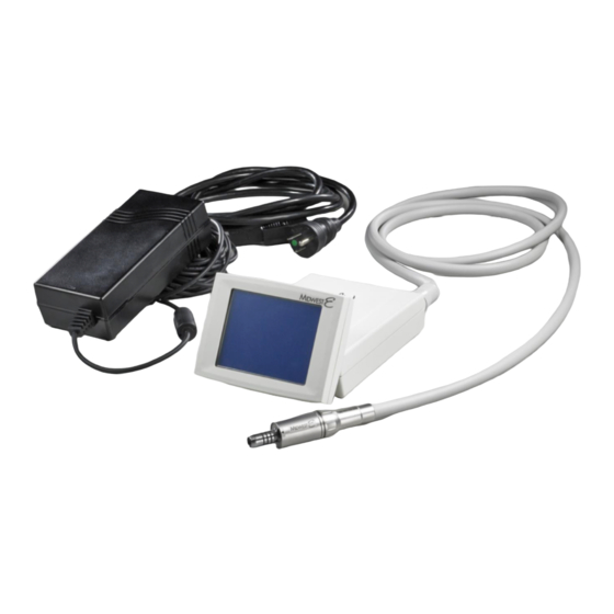
3 Product Overview Product Overview Overview of the Unit Figure 1 – Overview of the Unit LCD Screen Control Unit ® Midwest E Motor Power Supply Unit Power Supply - Main Cord Motor Hose Installation Bracket Page 8... -
Page 9: Back Panel
3 Product Overview Back Panel Figure 2 – Back Panel of the Unit 4-hole, 5-hole, or 6-pin Connector Power Supply Input Motor Hose Input Page 9... -
Page 10: Installation And Preparation For Use
4 Installation and Preparation for Use Installation and Preparation for Use WARNING: Installation of the device should be performed by a qualified service technician only Location A mounting accessory is supplied with the unit to aid installation of the system to a dental unit. The placement and mounting location of the device is at the discretion of the dental office. - Page 11 4 Installation and Preparation for Use Figure 4 – Connect Power Supply Connect Drive Air Tubing to the Control Unit Connect the 4-hole, 5-hole, or 6-pin air and water supply tubing (according ISO 9168) to the four-hole connection of the control unit (See Figure 5 below). CAUTION: Compressed air supply must be clean, dry, and free from oil per ISO 7494-2.
- Page 12 4 Installation and Preparation for Use Connect the Dental Motor 1. Connect the motor hose to the control unit Locate the motor hose pin connector on the back panel of the unit. Snap the hose male connector to the female end on the unit aligning the pins together as shown in the figure below. Figure 6 –...
-
Page 13: System Icons
4 Installation and Preparation for Use System Icons Icons/Keys Used to Program and Operate the Device: Button Icon Name Function Mode PREP Preparation Mode Main Menu ENDO Endodontic Mode Main Menu SETUP Set Up Mode Main Menu HANDPIECE LIGHT Instrument light on / off Main menu and Set up menu Submenu: illumination setting... - Page 14 4 Installation and Preparation for Use Button Icon Name Function Mode SPEED Bur speed Main menu E1 to E5 and P1 to P3 GEAR RATIO Ratio setting of the low speed Main menu E1 to E5 attachments and P1 to P3 E1, E2, E3, E4 Memory cell for Main menu...
-
Page 15: Set Up Mode
5 Set Up Mode Set Up Mode Set Up Mode Operations To enter in the Set Up Mode menu, press on the SETUP icon on the left of the home screen. You will then enter into the Set Up Mode Menu as shown in Figure 10 below. Setup Mode SETUP Mode Icon FACTORY RESET Icon... -
Page 16: Calibration
5 Set Up Mode Calibration ® Calibration of the Midwest E Electric Handpiece System should be performed each time the device has been installed or moved to different location where the air pressure from the foot pedal may vary. To Calibrate the Foot Control: 1. - Page 17 5 Set Up Mode To Turn ON/OFF Speaker Sound 1. Pressing the SPEAKER icon changes the operating status of the speaker. 2. If the icon has a slash through it, the speaker it is off; no slash indicates the speaker is on. To Adjust the Fiber Optic Handpiece Light Time Delay 1.
- Page 18 5 Set Up Mode To Adjust Standby Mode The standby mode switches off the display if the control is not active during the set time. By setting 0, the standby mode is switched off. By activating the foot control or touching the display, the display will wake up and all functions will be available. 1.
-
Page 19: General Operation
6 General Operation General Operation General Operation WARNING: To Promote Infection Control: Always adhere to protective measures when handling the device with patients. After use with a patient, spray air and water through the device for at least 20 seconds. ... -
Page 20: Operational Mode Options
6 General Operation Operational Mode Options ® The Midwest E Electric Handpiece System provides two operational Modes and one Set Up Mode for procedural use: Preparation Mode (PREP) For general preparation, Non-Endodontic Procedures; information on Operating Instructions using PREP mode, can be found in "Preparation Mode Operations" on page 20. ... -
Page 21: Preparation Mode
7 Preparation Mode Preparation Mode Preparation Mode Operations Preparation Mode (PREP) allows the user to regulate the motor speed, direction, and light source (on/off) of the handpiece system. ® E provides 4 default Memory Settings for ratio and speed (for details see the default values’ The Midwest table for ratio and speed in Table 1 below). - Page 22 7 Preparation Mode To Change Gear Ratio 4. Activate the gear ratio settings by pressing the GEAR RATIO icon. Select the appropriate increase or reduction ratio using the "+" or "-" Icons to match the gear ratio of the handpiece attachment currently being used.
-
Page 23: Endodontic Mode
8 Endodontic Mode Endodontic Mode Endodontic Mode Operations Endodontic Mode (ENDO) allows the user to regulate/change the motor speed, torque, operational direction, and auto reversing or stop options of the handpiece system. The combination of the torque and Torque-Stop Mode options in Endodontic Mode allows the user to designate the motor torque limits and direct the motor into auto reverse once the specified torque limit is reached. - Page 24 8 Endodontic Mode CAUTION: When using ENDO Mode, the spray air and spray water must be switched OFF at the dental unit or foot control. To Change ENDO Mode Memory Settings: 1. Turn on the device. 2. Press ENDO to access the Endodontic Mode presets. 3.
- Page 25 8 Endodontic Mode Change Torque-Stop Mode 15. Select the direction of the auto reverse option for endodontic procedures by pressing the TORQUE-STOP MODE icon. 16. Continue to press the TORQUE-STOP MODE icon until. The desired direction option is displayed. The choices will be: Auto-Stop Auto-Reverse Auto-Reverse Forward...
-
Page 26: Cleaning And Maintenance
E System. Maintenance WARNING: ® Repair and maintenance work on the Midwest E Electric Handpiece System must only be performed by authorized DENTSPLY personnel. DO NOT OPEN THE CONTROL BOX. There are no serviceable parts inside the control box. Page 26... -
Page 27: Troubleshooting
Error Code “ERR 84” - Phase short circuit Check for any damage on the tubing or motor assembly. Contact DENTSPLY Service Center on Page 32 if any damage found. Reset the system by powering the unit OFF/ON by disconnecting/re-connecting the power supply on the back of the unit. -
Page 28: Information On Electromagnetic Compatibility
11 Information on Electromagnetic Compatibility Information on Electromagnetic Compatibility The medical device is suitable for use in the specified electromagnetic environment. The purchaser or user of the medical device should ensure that it is used in an electromagnetic environment as described below: Emission Test Compliance Electromagnetic Environment... - Page 29 11 Information on Electromagnetic Compatibility NOTE: U is the alternating mains voltage before the test level is used. NOTE 1: At 80 MHz and 800 MHz, the higher frequency range applies. NOTE 2: These guidelines may not be applicable in every case. The spread of electromagnetic waves is absorbed and reflected by buildings, objects and people.
-
Page 30: Specifications
12 Specifications Specifications Control Unit 100 – 40,000 Rpm (min Motor speed range (forward / reverse): Output torque: max. 3.0 Ncm Motor current: max. 5.7 A / Phase Motor voltage: max. 22 V AC Operation mode: Duty cycle (0.5 on / 9 off) minutes Current of LED: max. -
Page 31: Recommended Input Settings
12 Specifications Recommended Input Settings System pressure: 4.0 bar (58 psi) Spray air: 1.0 bar (14.5 psi) Spray water: 0.8 bar (11.6 psi) Operating Conditions of Control Unit and Power Supply Location: Permitted in interior rooms Ambient temperature: 10 to 35ºC (50 to 95ºF) Relative humidity: 30 to 75 % Max. -
Page 32: Spare Parts
13 Spare Parts Spare Parts Spare Parts PART PART PART DESCRIPTION NUMBER 875040 CONTROL UNIT 875070 POWER SUPPLY & CORD ® 875045 MIDWEST E MOTOR ® 875055 MIDWEST E MOTOR O-RINGS ® 875060 MIDWEST E MOTOR HOSE CONNECTION O-RING ® 875065 MIDWEST E MOTOR SEAL... -
Page 33: Warranty
36 months from date of purchase (Note: the handpiece attachments are guaranteed for 24 months) – provided the unit has been operated and maintained as prescribed in these Instructions for Use, at the discretion of DENTSPLY, and has not been subject to apparent misuse, abuse or accident.
Need help?
Do you have a question about the Midwest E Electric Handpiece System and is the answer not in the manual?
Questions and answers