
Subscribe to Our Youtube Channel
Related Manuals for Orion MPA66-17


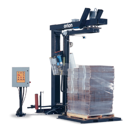
Summary of Contents for Orion MPA66-17
- Page 1 MODEL MPA66-17 SERIAL # 2005-8899999 2270 Industrial boul. , Montreal (Laval), Canada, H7S 1P9 Tel.: (450) 667-9769, Fax: (450) 667-6320...
- Page 2 INSTRUCTION MANUAL FOR ALL INQUIRIES PLEASE CONTACT OUR LOCAL DISTRIBUTOR FOR NORTH AMERICA ONLY 1-800-333-6556...
- Page 4 Thank choosing ORION stretch-wrapping equipment. It is a wise choice, which will benefit your company now and in the future. ORION uses a unique combination of functional, rugged steel structure and sophisticated control systems to offer equipment high durability maintenance requirements.
- Page 5 3)Subassembly ( see PART LIST ) SAFETY: ORION'S stretch wrappers should be operated with caution and common sense as any other industrial equipment. To prevent injury and/or electrical shocks, careful operation of the machine and awareness of its many automatic functions is required.
- Page 6 Minimum Load Size 30”W x 30”L x 26”H Weight Capacity Unlimited (Floor Loaded) Production Capacity Contact Orion for a Throughput Calculation Specific to your application Utilities 115/1/60 30 Amp Service 3 CFM Compressed Air @ 80 PSI Rotary Tower 20” Diameter Precision Ring Bearing Tower Support...
- Page 7 ORION PACKAGING SYSTEMS INC. SEMI-AUTOMATIC SPECIFICATIONS - EFFECTIVE SEPTEMBER 1st, 2000 REVISED APRIL 2001 ORION MODEL MPA66 Continued Film Tail Treatment Pneumatic Film Clamping Device Impulse Wire Film Cutting Pneumatic Load Seeking Brush Down System Structural Features 100% Structural Steel Construction Throughout...
- Page 8 2. Perform a visual inspection of the electrical and mechanical parts for loosened joints and / or broken connections. Any suspected shipping damage must be reported immediately to the freight carrier. Any transport damage cannot be claimed to Orion Packaging Inc. Items that are vulnerable to damage and must be inspected are as follows:...
-
Page 9: Machine Installation
MACHINE INSTALLATION After the visual inspection has been completed, the electrical power and the compressed air shall be connected as specified on the diagrams supplied with the machine. An electrical diagram is provided with each machine in the envelope attached to the panel box. ASSEMBLY PROCEDURE The structural frames of the machine have to be installed on a leveled floor. -
Page 10: Control Panel
CONTROL PANEL The control panel layout is custom designed for each particular installation. Please before proceeding be familiar with location of the EMERGENCY button and all functions, switches and pushbuttons. POWER SWITCHES Main Disconnect Switch ON - connects the power source to the machine. OFF - disconnects the power source. - Page 11 REWRAP SELECTOR The REWRAP selector is a pushbutton switch that restarts the wrapping cycle during the automatic operation. The REWRAP will work only when the operation switch is set to AUTO, and a load is in the proper position for wrapping on the turntable (process conveyor). CLAMP JOG The Clamp Jog is a bistable pushbutton (except “MA”...
-
Page 12: Film Tension
CARRIAGE CONTROL SWITCH The CARRIAGE CONTROL switch is a three position type switch with the Following settings: RAISE - raises the carriage until the top limit switch on the tower is attained. LOWER - lowers the carriage until the bottom limit switch on the tower is attained. This switch is normally positioned in the middle where the carriage remains stationary. -
Page 13: Limit Switches
TOP AND BOTTOM WRAPS There are two bistable, three position type switches controlling the number of wraps that may be put at the top and bottom of the load. TOP WRAPS: 1,2,3 BOTTOM WRAPS: 1,2,3 These switches may be set before the automatic cycle begins, and in their different positions will wrap respectively 1,2 or 3 turns of the film on the top or on the bottom of the load. -
Page 14: Proximity Switch
PROXIMITY SWITCH Proximity Switch is located under the turntable next to the lock, or on the perch (“MA” type machine). Its purpose is to monitor the turntable or rotary arm position, and to signal the controller every time the turntable or rotary arm passes the home position. The proximity switches proper adjustment ensures that turntable or rotary tower will stop in the correct position for the lock to be activated (only turntable machine). -
Page 17: Loading The Film
LOADING THE FILM The film roll can be loaded on the carriage mandrel from either end of the roll. When using tacky film, please verify that the inward tacky surface of the film is inward on the load. 1. Disconnect power (turn off power switch). 2. -
Page 20: Machine Maintenance
MACHINE MAINTENANCE All general information about machine maintenance is based on normal machine working conditions: indoor, moderate dust and low moisture environment, and maximum rotation of 32 RPM of turntable/rotary arm. They should be regarded as guidelines, reviewed and corrected according to requirements of actual use and conditions. -
Page 21: Chain Maintenance
Externally: by lubricating and wiping the chain drive with oily cloth. The frequency of lubrication depends on entirely upon the usage of the machine and environment in which the machine is placed (dust, moisture etc.). Machines working under extremely dirty conditions should be lubricated every 400 operating hours but at minimum, every 2 months. - Page 22 FULLY AUTOMATIC STANDARD ASSEMBLY PART LIST Note : * Quantity listed in order of part number ** The names given to the parts are generic...
- Page 30 APPENDIX...
- Page 33 MULTISTRETCH MOTOR CONTROL BOARD CALIBRATION INSTRUCTIONS FOR 336-8/10 BOARD Adjustments Bias: (RV3) The RV3 pot controls the system bias. This control injects an offset voltage that adds or subtracts from the voltage reference defined by the External Tension Adjustment (Film Tension Potentiometer).
- Page 34 a safe level regardless of motor load or input from the tension-arm. This pot is factory pre-set to suit ½ hp motors. Should changes be required in the field, proceed as follows: Monitor the motor current. Advance the pot slowly until the desired current is achieved.
-
Page 37: Installation
66 & 55 series Orion stretch wrapping equipment. The following calibration instructions apply to all 66 & 55 series turntable and rotary tower type machinery, but it will be important to note specific reference to your particular Orion model for best calibration results. - Page 38 ADJUSTMENTS Acceleration: (RV3) The pot marked A is the control for the acceleration or electronic soft start feature. For an initial setting, turn the A pot fully counter-clockwise (CCW) until a faint “clicking” sound is heard, then approximately 2 turns (or revolutions) clockwise (CW).
-
Page 39: Troubleshooting And Repair
TROUBLE SHOOTING & REPAIR In most cases, repair will require parts replacement. If user intends to, and is equipped to perform repairs, spare parts are available from Orion Parts & Service. Damage is usually visually evident on the 850M board. Replacing the obviously damaged board frequently restores operation.
Need help?
Do you have a question about the MPA66-17 and is the answer not in the manual?
Questions and answers