
Related Manuals for Orion H66-14


Summary of Contents for Orion H66-14
- Page 1 MODEL H66-14 SERIAL # 2270 Industrial boul. , Montreal (Laval), Canada, H7S 1P9 Tel.: (450) 667-9769, Fax: (450) 667-6320...
- Page 2 INSTRUCTION MANUAL FOR ALL INQUIRIES PLEASE CONTACT OUR LOCAL DISTRIBUTOR FOR NORTH AMERICA ONLY 1-800-333-6556...
- Page 3 Thank choosing ORION stretch-wrapping equipment. It is a wise choice, which will benefit your company now and in the future. ORION uses a unique combination of functional, rugged steel structure and sophisticated control systems to offer equipment high durability maintenance requirements.
- Page 4 3)Subassembly ( see PART LIST ) SAFETY: ORION'S stretch wrappers should be operated with caution and common sense as any other industrial equipment. To prevent injury and/or electrical shocks, careful operation of the machine and awareness of its many automatic functions is required.
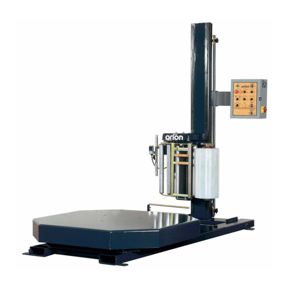
- Page 5 Turntable Jog Pushbutton Selectable Bottom Wraps First / Top Wraps First Operation Film Delivery 20” Orion Insta-Thread™ Powered Prestretch Film Delivery System Precision Ground, Polyeurethane Pre-Stretch Rollers for Consistent, Maximum Film Yield 245% Standard Pre-Stretch Ratio (Maximum 395%) Easy & Safe to Operate Self-Threading Carriage Design...
- Page 6 2. Perform a visual inspection of the electrical and mechanical parts for loosened joints and / or broken connections. Any suspected shipping damage must be reported immediately to the freight carrier. Any transport damage cannot be claimed to Orion Packaging Inc. Items that are vulnerable to damage and must be inspected are as follows:...
-
Page 7: Machine Installation
MACHINE INSTALLATION After the visual inspection has been completed, the electrical power and the compressed air shall be connected as specified on the diagrams supplied with the machine. An electrical diagram is provided with each machine in the envelope attached to the panel box. -
Page 9: Machine Operation
MACHINE OPERATION Before Starting Machine Operation Verify that the machine is properly connected to the electrical source. The electrical requirements depend on the machine type and features. For this information, please see the machine electrical diagram provided with the machine operation manual. The control panel layout for the machine is shown on the drawing. - Page 10 TOP WRAPS FIRST - When this Sub-Mode has been selected film carriage will move to top of load and stop. Selected number of top wraps will be applied. The film carriage will then move to bottom of the load and stop. Selected number of bottom wraps will then be applied. The film carriage will be in bottom position;...
- Page 11 FILM TENSION Film tension may be adjusted using the film tension control knob. It has a range of tension from 0 to 10 (0 to 4 the low range, 4 to 8 the most useful range for most of the films used by our customers, 8 to 10 as a very high range which may break some films).
-
Page 12: Loading The Film
MACHINE WRAPPING TEST Notice: It is advisable to test-run the equipment with several pallet loads before attempting to wrap using film. Please position the operator beside the EMERGENCY STOP push button. Start up of the machine (system) may determine the need for the adjustment of: - Load height stop photoswitch (on the carriage) - Top limit switch position - Bottom limit switch position... - Page 14 PROXIMITY SENSOR ADJUSTMENT Occasionally the Feed Back Proximity Sensor may need some adjustment. The position of the feed back proximity sensor against the cam is shown on drawing # 419139. Adjustment instructions: - Remove the carriage cover - Unbolt the two nuts holding the proximity switch - item # 1 - Turn the Proximity sensor - (item # 2) to create the gap between the cam and the front side of proximity sensor about 1/8 “...
-
Page 15: Machine Maintenance
MACHINE MAINTENANCE All general information about machine maintenance is based on normal machine working conditions: indoor, moderate dust and low moisture environment, and maximum rotation of 32 RPM of turntable/rotary arm. They should be regarded as guidelines, reviewed and corrected according to requirements of actual use and conditions. MOTOR MAINTENANCE An occasional inspection of the brushes should be made in order to establish a wear rate. -
Page 16: Chain Maintenance
Externally: by lubricating and wiping the chain drive with oily cloth. The frequency of lubrication depends on entirely upon the usage of the machine and environment in which the machine is placed (dust, moisture etc.). Machines working under extremely dirty conditions should be lubricated every 400 operating hours but at minimum, every 2 months. - Page 19 SEMI-AUTOMATIC STANDARD ASSEMBLY PART LIST Note : * Quantity listed in order of part number ** The names given to the parts are generic...
- Page 26 APPENDIX...
- Page 28 MULTISTRETCH 336-6/7/9 MOTOR CONTROL BOARD CALIBRATION INSTRUCTIONS Bias: (RV3) The RV3 pot controls the system bias. This control injects an offset voltage that adds or subtracts from the voltage reference defined by the external tension adjustment (film tension potentiometer); this will allow extremes of adjustment to be set to levels consistent with proper operation.
- Page 29 This pot is factory pre-set to suit ½ HP motors. Should changes be required in the field, proceed as follows: Monitor the motor current. Turn the current limit RV4 to minimum (full CCW). Stall the motor. Advance the pot slowly until the desired current is achieved.
-
Page 31: Installation
66 & 55 series Orion stretch wrapping equipment. The following calibration instructions apply to all 66 & 55 series turntable and rotary tower type machinery, but it will be important to note specific reference to your particular Orion model for best calibration results. - Page 32 ADJUSTMENTS Acceleration: (RV3) The pot marked A is the control for the acceleration or electronic soft start feature. For an initial setting, turn the A pot fully counter-clockwise (CCW) until a faint “clicking” sound is heard, then approximately 2 turns (or revolutions) clockwise (CW).
-
Page 33: Troubleshooting And Repair
TROUBLE SHOOTING & REPAIR In most cases, repair will require parts replacement. If user intends to, and is equipped to perform repairs, spare parts are available from Orion Parts & Service. Damage is usually visually evident on the 850M board. Replacing the obviously damaged board frequently restores operation.
Need help?
Do you have a question about the H66-14 and is the answer not in the manual?
Questions and answers