Table of Contents
Advertisement
Quick Links
INSTALLATION, OPERATION, MAINT.
200, 230,
*During model development, the following models received updated nomenclature:
460 & 575 Models
With EPROM
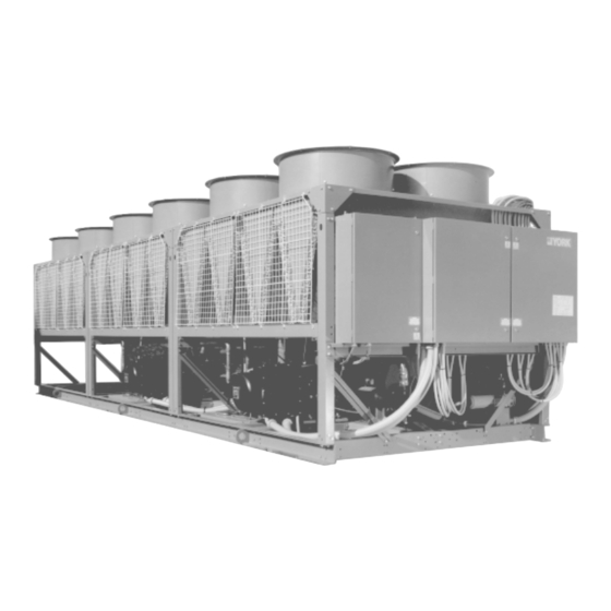
AIR COOLED SCREW LIQUID CHILLERS
Supersedes: 201.10-NM1 (496)
140 - 250 TON MODELS (Standard Efficiency)
215 - 260 TON MODELS (High Efficiency)*
60 HERTZ
STYLE D
OLD
YCAS 316
YCAS 336
YCAS 366
031-01714-001
Millennium
AIR COOLED SCREW HERMETIC
27960A
NEW
YCAS 216X
YCAS 236X
YCAS 266X
(Standard, Brine & Metric Models, Combined)
TM
Form 201.10-NM1 (697)
28507A
®
•
•
Advertisement
Table of Contents

Related Manuals for York Millennium YCAS 316


Summary of Contents for York Millennium YCAS 316
- Page 1 Millennium AIR COOLED SCREW LIQUID CHILLERS AIR COOLED SCREW HERMETIC Supersedes: 201.10-NM1 (496) INSTALLATION, OPERATION, MAINT. Form 201.10-NM1 (697) 140 - 250 TON MODELS (Standard Efficiency) 215 - 260 TON MODELS (High Efficiency)* 60 HERTZ STYLE D 27960A 28507A 200, 230, *During model development, the following models received updated nomenclature: 460 &...
-
Page 2: Table Of Contents
Unit On/Off Switch, System Controls, and Other Controls ......125 YCAS 140 - 246 Fan Control Strategy ............. 131 YCAS 216X - 266X Fan Control Strategy ............132 System Startup Checklist ................133 Operating Sequence ..................137 Troubleshooting ....................138 Temperature Conversion Table ................. 144 YORK INTERNATIONAL... -
Page 3: General Chiller Information
ASME, and U.L. (200, 230, 460 and 575-3- assembly, an operational test is performed with water 60 models). Units are rated in accordance with ARI flowing through the cooler to check that each refrigeration Standard 550. circuit operates correctly. YORK INTERNATIONAL... - Page 4 UNIT NOMENCLATURE The model number denotes the following characteristics of the unit: YORK Chiller Design Series Air Cooled Type Start Y = WYE-Delta X = Across-the-Line Compressor Design Series S = Screw Unit Model Voltage Code: 17 = 200-3-60 Class...
-
Page 5: Nomenclature
8 = 124 Frame, 10.75" Long (P) Motor in System #2 Compressor 9 = 124 Frame, 10.75" Long (M) (See System #1 motor list) Gear in System #2 XHS 120 Compressor (A, M, F, H, P or S) YORK INTERNATIONAL... -
Page 6: Operational Limitations
1. Units can be used for brine temperatures down to 35°F by reset- ting standard controls. For leaving brine temperatures down to 10°F, contact your nearest YORK representative for application requirements. 2. Operation above 115°F requires the Optional High Ambient Kit. - Page 7 1. Units can be used for brine temperatures down to 1.7°C by resetting standard controls. For leaving brine temperatures down to -12.2°C, contact your nearest YORK representative for appli- cation requirements. 2. Operation above 46°C requires the Optional High Ambient Kit.
-
Page 8: Physical Data
19,714 SHIPPING Cu. FIN 21,980 17,598 21,980 17,598 21,980 WEIGHT (LBS.) Al. FIN 22,961 15,722 22,961 15,722 22,961 OPERATING Cu. FIN 25,227 17,998 25,227 17,998 25,227 Sys. 1 REFRIGERANT CHARGE (LBS. R-22) Sys. 2 * = Voltage Code YORK INTERNATIONAL... - Page 9 8942 SHIPPING Cu. FIN 9970 7982 9970 7982 9970 WEIGHT (KG) Al. FIN 10415 7131 10415 7131 10415 OPERATING Cu. FIN 11443 8164 11443 8164 11443 Sys. 1 REFRIGERANT CHARGE (KG R-22) Sys. 2 * = Voltage Code YORK INTERNATIONAL...
-
Page 10: Ycas 140-246 Dimensions
LD01445(R) NOTES: 1. Clearances - Recommended YORK clearances for peak performance, reliable operation and maintenance: Side to wall 8'–0"*; Rear to wall 8'–0"; Control Panel End to wall 5'–0"*; Over the top - No obstructions allowed; Distance between adjacent units 12'–0", (Walls should be no higher than the unit.) *No more than one high wall can be higher than the top of the unit. - Page 11 FORM 201.10-NM1 YCAS 140-246 DIMENSIONS (English) LD01446 LD01444 YORK INTERNATIONAL...
- Page 12 LD01441(R) NOTES: 1. Clearances - Recommended YORK clearances for peak performance, reliable operation and maintenance: Side to wall 2438 mm*; Rear to wall 2438 mm; Control Panel End to wall 1524 mm*; Over the top - No obstructions allowed; Distance between adjacent units 3658 mm, (Walls should be no higher than the unit.)
- Page 13 FORM 201.10-NM1 YCAS 140-246 DIMENSIONS (SI) LD01442 LD01440 YORK INTERNATIONAL...
-
Page 14: Ycas 216X - 266X Dimensions
LD01453(R) NOTES: 1. Clearances - Recommended YORK clearances for peak performance, reliable operation and maintenance: Side to wall 8'–0"*; Rear to wall 8'–0"; Control Panel End to wall 5'–0"*; Over the Top - No obstructions allowed; Distance between adjacent units 12'–0", (Walls should be no higher than the unit.) *No more than one wall can be higher than the top of the unit. - Page 15 FORM 201.10-NM1 YCAS 216X - 266X DIMENSIONS (English) LD01454 LD01454 YORK INTERNATIONAL...
- Page 16 LD01449(R) NOTES: 1. Clearances - Recommended YORK clearances for peak performance, reliable operation and maintenance: Side to wall 2438 mm*; Rear to wall 2438 mm; Control Panel End to wall 1524 mm*; Over the top - No obstructions allowed; Distance between adjacent units 3658 mm, (Walls should be no higher than the unit.)
- Page 17 FORM 201.10-NM1 YCAS 216X - 266X DIMENSIONS (SI) LD01450 LD01448 YORK INTERNATIONAL...
-
Page 18: Electrical Data
The supplied disconnect is a “Disconnecting Means” as defined in N.E.C. 100.B, and is intended for isolating the unit from the available power supply to perform maintenance and troubleshooting. This disconnect is not intended to be a Load Break Device. YORK INTERNATIONAL... - Page 19 MIN NF MINIMUM NON-FUSED RUNNING LOAD AMPS S.P. WIRE SINGLE POINT WIRING UNIT MTD SERV SW UNIT MOUNTED SERVICE (NON FUSED DISCONNECT SWITCH) WYE-DELTA WYE-DELTA START XLRA ACROSS-THE-LINE INRUSH LOCKED ROTOR AMPS YLRA WYE-DELTA INRUSH LOCKED ROTOR AMPS YORK INTERNATIONAL...
- Page 20 (3) 3/0-500 YCAS236 (2) #2-600 (3) 3/0-500 (2) #2-600 (3) 3/0-500 YCAS236X (2) #2-600 (3) 3/0-500 (2) #2-600 (3) 3/0-500 YCAS246 (2) #2-600 (3) 3/0-500 (2) #2-600 (3) 3/0-500 YCAS266X (2) #2-600 (3) 3/0-500 See page 18 for notes. YORK INTERNATIONAL...
- Page 21 MIN NF MINIMUM NON-FUSED RUNNING LOAD AMPS S.P. WIRE SINGLE POINT WIRING UNIT MTD SERV SW UNIT MOUNTED SERVICE (NON FUSED DISCONNECT SWITCH) WYE-DELTA WYE-DELTA START XLRA ACROSS-THE-LINE INRUSH LOCKED ROTOR AMPS YLRA WYE-DELTA INRUSH LOCKED ROTOR AMPS YORK INTERNATIONAL...
- Page 22 1000 1000 (3) 3/0-500 YCAS236 (3) 3/0-500 (3) 3/0-500 (3) 3/0-500 YCAS236X (3) 3/0-500 (3) 3/0-500 1000 1000 1000 1000 1000 (3) 3/0-500 YCAS246 (3) 3/0-500 (3) 3/0-500 (3) 3/0-500 YCAS266X (3) 3/0-500 See page 18 for notes. YORK INTERNATIONAL...
- Page 23 MIN NF MINIMUM NON-FUSED RUNNING LOAD AMPS S.P. WIRE SINGLE POINT WIRING UNIT MTD SERV SW UNIT MOUNTED SERVICE (NON FUSED DISCONNECT SWITCH) WYE-DELTA WYE-DELTA START XLRA ACROSS-THE-LINE INRUSH LOCKED ROTOR AMPS YLRA WYE-DELTA INRUSH LOCKED ROTOR AMPS YORK INTERNATIONAL...
- Page 24 1000 1000 (3) 3/0-500 YCAS236 (3) 3/0-500 (3) 3/0-500 (3) 3/0-500 YCAS236X (3) 3/0-500 (3) 3/0-500 1000 1000 1000 1000 1000 (3) 3/0-500 YCAS246 (3) 3/0-500 (3) 3/0-500 (3) 3/0-500 YCAS266X (3) 3/0-500 See page 18 for notes. YORK INTERNATIONAL...
- Page 25 MIN NF MINIMUM NON-FUSED RUNNING LOAD AMPS S.P. WIRE SINGLE POINT WIRING UNIT MTD SERV SW UNIT MOUNTED SERVICE (NON FUSED DISCONNECT SWITCH) WYE-DELTA WYE-DELTA START XLRA ACROSS-THE-LINE INRUSH LOCKED ROTOR AMPS YLRA WYE-DELTA INRUSH LOCKED ROTOR AMPS YORK INTERNATIONAL...
-
Page 26: Ycas 140 - 246 Chiller Components
YCAS 140 - 246 CHILLER COMPONENTS POWER PANEL MICRO PANEL LIQUID STOP VALVE 27960A COMPRESSOR #1 COMPRESSOR #2 FILTER DRYER YORK INTERNATIONAL... - Page 27 FORM 201.10-NM1 ORIFICE CONDENSER COIL FILTER DRYER OUTLET 27960A EVAPORATOR HEATER INLET EVAPORATOR ECONOMIZER TXV’S LIQUID LINE FILTER DRYER SOLENOID VALVES YORK INTERNATIONAL...
-
Page 28: Ycas 216X - 266X Chiller Components
YCAS 216X - 266X CHILLER COMPONENTS MICRO PANEL POWER PANEL LIQUID STOP VALVE 28507A COMPRESSOR #2 FILTER DRYER COMPRESSOR #1 YORK INTERNATIONAL... - Page 29 FORM 201.10-NM1 FAN ORIFICE CONDENSER COIL 28508A FILTER OUTLET EVAPORATOR INLET FILTER ECONOMIZER DRYER DRYER EVAPORATOR HEATER YORK INTERNATIONAL...
- Page 30 OIL DRAIN MUFFLER LINE 28509A SUCTION PIPING DISCHARGE PIPING DISCHARGE TEMPERATURE SENSOR SLIDE VALVE SUCTION PISTON OIL SERVICE VALVE SUPPLY / VENT LINE DISCHARGE SERVICE VALVE OIL HEATER ELECTRICAL JUNCTION DISCHARGE PRESSURE TRANSDUCER EVAPORATOR OPTIONAL DISCHARGE MUFFLER 28513A YORK INTERNATIONAL...
- Page 31 FORM 201.10-NM1 SYS 1 TXV SYS 1 SIGHT GLASS SYS 2 TXV SYS 1 LIQUID LINE SOLENOID SYS 2 SYS 2 SIGHT LIQUID GLASS LINE SOLENOID 28512A YORK INTERNATIONAL...
- Page 32 PIPING SOLENOID OIL INJECTION PIPING OIL PRESSURE TRANSDUCER OIL SEPARATOR OIL FILTER 5 TON TXV MOTOR COOLING SUB COOLER PIPING (ECONOMIZER) LIQUID INJECTION SOLENOID 15 TON TXV VALVE LIQUID SUPPLY SOLENOID 5 TON TXV 15 TON TXV 28511A YORK INTERNATIONAL...
- Page 33 FORM 201.10-NM1 LIQUID STOP VALVE FILTER DRYER 28514A YORK INTERNATIONAL...
-
Page 34: Compressor Components
COMPRESSOR COMPONENTS COMPRESSOR SIDE VIEW (MAY BE ON SIDE OR REAR OF MOTOR COVER) COMPRESSOR SIDE VIEW LD01091 YORK INTERNATIONAL... - Page 35 FORM 201.10-NM1 COMPRESSOR TOP VIEW COMPRESSOR REAR VIEW COMPRESSOR FRONT VIEW LD01092 NOTE: *On newer production chillers, this valve will not be located on the compressor. YORK INTERNATIONAL...
- Page 36 GAS OFF ECONOMIZER HEAT EXCHANGER OIL INJECTION MOTOR TERMINAL SUCTION DISCHARGE LIQUID INJECTION LD01093 FIG. 2 – COMPRESSOR GAS FLOW YORK INTERNATIONAL...
- Page 37 FORM 201.10-NM1 LD01285 FIG. 3 – SCREW CHILLER REFIGERANT FLOW DIAGRAM YORK INTERNATIONAL...
-
Page 38: General
150 PSIG, and 235 PSIG for the tube (refrigerant side). The cooler is equipped with a heater to provide ACTUAL freeze protection to -20°F (-28.8°C). ROTOR ASSEMBLY Water connections are grooved to accept victaulic 27936A(D) couplings. FIG. 4 – COMPRESSOR ROTORS YORK INTERNATIONAL... - Page 39 The oil (YORK “E” oil - used for R-22 applications), which water temperature (LWT) within the programmed Control drains back into the compressor through a replaceable 0.5 Range (CR).
- Page 40 1A or 2A “TRANSITION” contactor opens removing the resistor network and completing the Two types of compressor motor starting are available: “DELTA” connection of the “WYE-DELTA” start. FIG. 5 – POWER PANEL (WITH WYE-DELTA STARTING) 27963A YORK INTERNATIONAL...
-
Page 41: Installation
4. Pipe unit using good piping practice (see ASHRAE entrance to the condenser coil, for air discharge away handbook section 215 and 195 or YORK Service from the condenser, and for servicing access. Manuals for detailed piping). - Page 42 Chiller noise is a result of compressor and fan operation. Con- siderations should be made utilizing noise levels published in the YORK Engineering Guide for the specific chiller model. If questions arise, contact YORK PRODUCT MARKETING.
- Page 43 FORM 201.10-NM1 Hand stop valves should be installed in all lines to 7. A chilled water flow switch, (either by YORK or others) facilitate servicing. MUST be installed in the leaving water piping of the cooler. There should be a straight horizontal run of at Piping to the inlet and outlet connections of the chiller least 5 diameters on each side of the switch.
-
Page 44: Ycas 140 - 246 Weight Distributions
1912 1847 2085 2019 1952 1886 YCAS246 2043 1977 1912 1847 2085 2019 1952 1886 NOTE: USE CP-2-31 ISOLATORS AT ALL LOCATIONS LD01445(R) TYPE MAX. LOAD SPRING DEFL & SIZE LBS. COLOR CP-2-31 2200 GRAY 0.83 LD01089 CP-2-31 YORK INTERNATIONAL... - Page 45 2197 2132 2369 2303 2237 2171 YCAS246 2327 2262 2197 2132 2369 2303 2237 2171 NOTE: USE CP-4-26 ISOLATORS AT ALL LOCATIONS LD01445(R) TYPE MAX. LOAD SPRING DEFL & SIZE LBS. COLOR CP-4-26 2400 PURPLE 1.17 LD01168 CP-4-26 YORK INTERNATIONAL...
- Page 46 OPERATING WEIGHT DISTRIBUTION (Kg) AND ISOLATOR LOCATION MODEL YCAS140 YCAS160 YCAS170 YCAS180 YCAS190 YCAS216 YCAS236 YCAS246 NOTE: USE CP-2-31 ISOLATORS AT ALL LOCATIONS LD01441(r) TYPE MAX. LOAD SPRING DEFL & SIZE COLOR CP-2-31 997.9 GRAY 21.0 LD01089 CP-2-31 YORK INTERNATIONAL...
- Page 47 1026 1075 1045 1015 YCAS236 1056 1026 1075 1045 1015 YCAS246 1056 1026 1075 1045 1015 NOTE: USE CP-4-26 ISOLATORS AT ALL LOCATIONS LD01441(r) TYPE MAX. LOAD SPRING DEFL & SIZE COLOR CP-4-26 1088.6 PURPLE 29.7 LD01168 CP-4-26 YORK INTERNATIONAL...
-
Page 48: Ycas 216X - 266X Weight Distributions
1808 1600 1391 1182 ISOLATOR CP-2-31 CP-2-31 CP-2-31 CP-2-27 CP-2-27 CP-2-27 CP-2-31 CP-2-31 CP-2-31 CP-2-27 CP-2-27 CP-2-27 LD01453)R) TYPE MAX. LOAD SPRING DEFL & SIZE LBS. COLOR CP-2-27 1500 ORANGE 1.06 CP-2-31 2200 GRAY LD01089 CP-2-27 / CP-2-31 YORK INTERNATIONAL... - Page 49 1884 1676 1468 ISOLATOR CP-2-32 CP-2-32 CP-2-32 CP-2-28 CP-2-28 CP-2-28 CP-2-32 CP-2-32 CP-2-32 CP-2-28 CP-2-28 CP-2-28 LD01453(R) TYPE MAX. LOAD SPRING DEFL & SIZE LBS. COLOR CP-2-28 1800 GREEN 1.02 CP-2-32 2600 WHITE 0.74 LD01089 CP-2-28 / CP-2-32 YORK INTERNATIONAL...
- Page 50 ISOLATOR CP-2-31 CP-2-31 CP-2-31 CP-2-27 CP-2-27 CP-2-27 CP-2-31 CP-2-31 CP-2-31 CP-2-27 CP-2-27 CP-2-27 YCAS266x 1010 ISOLATOR CP-2-31 CP-2-31 CP-2-31 CP-2-27 CP-2-27 CP-2-27 CP-2-31 CP-2-31 CP-2-31 CP-2-27 CP-2-27 CP-2-27 LD01449(R) TYPE MAX. LOAD SPRING DEFL & SIZE COLOR CP-2-27 680.4 ORANGE 26.9 CP-2-31 997.9 GRAY 21.0 LD01089 CP-2-27 / CP-2-31 YORK INTERNATIONAL...
- Page 51 1122 10209 1139 1044 ISOLATOR CP-2-32 CP-2-32 CP-2-32 CP-2-28 CP-2-28 CP-2-28 CP-2-32 CP-2-32 CP-2-32 CP-2-28 CP-2-28 CP-2-28 LD01449(R) TYPE MAX. LOAD SPRING DEFL & SIZE COLOR CP-2-28 816.4 GREEN 25.9 CP-2-32 1179.3 WHITE 18.7 LD01089 CP-2-28 / CP-2-32 YORK INTERNATIONAL...
-
Page 52: Ycas 140 - 246 Wiring Diagrams
LEGEND Transient Voltage Suppression Terminal Block for Customer Connections Terminal Block for Customer Low Voltage (Class 2) Connections. See Note 2 Terminal Block for YORK Connections Only Wiring and Components by YORK Optional Equipment Wiring and/or Components by Others NOTES: 1. - Page 53 Any contacts con- nected to flow switch inputs or BAS inputs on terminals 13 - 19 or TB3, or any other ter- minals, must be sup- pressed with a YORK P/N 031-00808-000 suppressor across the relay/contactor coil. CAUTION: Control wiring con-...
- Page 54 YCAS 140 - 246 CONNECTION DIAGRAM (SYSTEM WIRING) LD01466(D) FIG. 9 – SYSTEM WIRING YORK INTERNATIONAL...
- Page 55 FORM 201.10-NM1 YCAS 140 - 246 COMPRESSOR TERMINAL BOX LD01466(D) ACROSS-THE-LINE START LD01459(D) WYE-DELTA START FIG. 9 – CONTINUED YORK INTERNATIONAL...
- Page 56 LEGEND Transient Voltage Suppression Terminal Block for Customer Connections Terminal Block for Customer Low Voltage (Class 2) Connections. See Note 2 Terminal Block for YORK Connections Only Wiring and Components by YORK Optional Equipment Wiring and/or Components by Others NOTES: 1.
- Page 57 Any contacts con- nected to flow switch inputs or BAS inputs on terminals 13 - 19 or TB3, or any other ter- minals, must be sup- pressed with a YORK P/N 031-00808-000 suppressor across the relay/contactor coil. CAUTION: Control wiring con-...
- Page 58 YCAS 140 - 246 CONNECTION DIAGRAM ACROSS-THE-LINE LD01465(D) FIG. 11 – CONNECTION DIAGRAM – ACROSS-THE LINE YORK INTERNATIONAL...
- Page 59 FORM 201.10-NM1 LD01465(D) FIG. 11 – CONTINUED YORK INTERNATIONAL...
- Page 60 YCAS 140 - 246 CONNECTION DIAGRAM WYE-DELTA LD01458(D) FIG. 12 – CONNECTION DIAGRAM – WYE-DELTA YORK INTERNATIONAL...
- Page 61 FORM 201.10-NM1 LD01458(D) FIG. 12 – CONTINUED YORK INTERNATIONAL...
-
Page 62: Ycas 216X - 266X Wiring Diagrams
LEGEND Transient Voltage Suppression Terminal Block for Customer Connections Terminal Block for Customer Low Voltage (Class 2) Connections. See Note 2 Terminal Block for YORK Connections Only Wiring and Components by YORK Optional Equipment Wiring and/or Components by Others NOTES: 1. - Page 63 Any contacts con- nected to flow switch inputs or BAS inputs on terminals 13 - 19 or TB3, or any other ter- minals, must be sup- pressed with a YORK P/N 031-00808-000 suppressor across the relay/contactor coil. CAUTION: Control wiring con-...
- Page 64 YCAS 216X - 266X CONNECTION DIAGRAM (SYSTEM WIRING) LD01207(D) FIG. 14 – YCAS 216X - 266X SYSTEM WIRING YORK INTERNATIONAL...
- Page 65 FORM 201.10-NM1 YCAS 216X - 266X COMPRESSOR TERMINAL BOX LD01207(D) ACROSS-THE-LINE START LD01203(D) WYE-DELTA START FIG. 14 – CONTINUED YORK INTERNATIONAL...
- Page 66 LEGEND Transient Voltage Suppression Terminal Block for Customer Connections Terminal Block for Customer Low Voltage (Class 2) Connections. See Note 2 Terminal Block for YORK Connections Only Wiring and Components by YORK Optional Equipment Wiring and/or Components by Others NOTES: 1.
- Page 67 Any contacts con- nected to flow switch inputs or BAS inputs on terminals 13 - 19 or TB3, or any other ter- minals, must be sup- pressed with a YORK P/N 031-00808-000 suppressor across the relay/contactor coil. CAUTION: Control wiring con-...
- Page 68 YCAS 216X - 266X CONNECTION DIAGRAM ACROSS-THE-LINE LD01206(D) FIG. 16 – YCAS 216X - 266X CONNECTION DIAGRAM – ACROSS-THE-LINE YORK INTERNATIONAL...
- Page 69 FORM 201.10-NM1 LD01206(D) FIG. 16 – CONTINUED YORK INTERNATIONAL...
- Page 70 YCAS 216X - 266X CONNECTION DIAGRAM WYE-DELTA LD01202(D) FIG. 17 – YCAS 216X - 266X CONNECTION DIAGRAM – WYE-DELTA YORK INTERNATIONAL...
- Page 71 FORM 201.10-NM1 LD01202(D) FIG. 17 – CONTINUED YORK INTERNATIONAL...
-
Page 72: Unit Controls And Operation
INTRODUCTION Compressor starting, stopping, loading and unloading decisions are performed by the Microprocessor to The YORK Millennium Computer Control Center is a maintain leaving water temperatures. These decisions microprocessor based control system capable of multi- are a function of temperature deviation from setpoint and circuit control to maintain chilled liquid temperature and the rate of change of temperature. - Page 73 All of these not lost during a power failure regardless of the time signals are sent to the I/O Expansion Board which involved in a power outage or shutdown period. multiplexes them and then feeds them to the Microprocessor Board. YORK INTERNATIONAL...
- Page 74 I/O EXPANSION BOARD POWER SUPPLY BOARD RELAY OUTPUT BOARD #1 RELAY OUTPUT BOARD #2 TERMINAL BLOCK (TERMINALS 13 - 19) FLOW SWITCH, TEMP PWM, LEAD/LAG, ETC. 27962A MICROPROCESSOR BOARD FIG. 19 – MICROCOMPUTER CONTROL CENTER YORK INTERNATIONAL...
- Page 75 10, 11 & 12 C.T.’S (MOTOR OVERLOAD) 27963A EARTH SYS 2 SYS 1 POWER WIRING CONNECTIONS GROUND POWER WIRING CONNECTIONS CONNECTIONS NOTE: SYS 2 CONTACTORS NOTE: SYS 2 CONTACTORS NOT VISIBLE NOT VISIBLE FIG. 20 – WYE-DELTA START POWER PANEL YORK INTERNATIONAL...
-
Page 76: Display Keys
2 seconds, the appropriate key for the desired display The minimum limit on the display is -4.6°F (-20.3°C). The may be pushed and held. Updating will be at 0.4 second maximum limit on the display is 137.9°F (58.8°C). intervals. YORK INTERNATIONAL... - Page 77 D I S H 1 1 3 0 . 0 ° F • Saturated Discharge Temperature is computed by S A T S U C T 1 2 4 . 3 ° F converting discharge pressure to temperature. YORK INTERNATIONAL...
- Page 78 S Y S S L I D E V A L V E Demand limit can be accomplished remotely by a YORK P O S I T I O N 1 0 0 % ISN system or an external PWM (dry contact closure) from an EMS system connected to the micro.
- Page 79 R E F R I G E R A N T T Y P E R E F R I G E R A N T T Y P E R 1 3 4 A R 2 2 YORK INTERNATIONAL...
- Page 80 The low ambient cut-out is programmable from 0 - 50°F. programmed from 10 - 70°F. This mode also allows the Low Chilled Liquid Cut-out to be programmable from 8 - 36°F and the Suction Pressure Cut-out from 20 - 70 PSIG. YORK INTERNATIONAL...
- Page 81 This MUST be selected for chillers with Wye-Delta selection of control from either thermal expansion valves starters where three contactors and wire wound power or electronic expansion valves. resistors are present for each compressor in the power panel. YORK INTERNATIONAL...
- Page 82 The micro will then assign the “lead” to the compressor with the shortest anti-recycle time. If both compressors are shut down, the micro will start the first available compressor in an effort to maintain control of temperature as soon as possible. YORK INTERNATIONAL...
-
Page 83: Status Key
ON. The lag system will display this message on the Control Panel is in the OFF position which will not until the loading sequence is ready for the lag system to allow the chiller to run. start. YORK INTERNATIONAL... - Page 84 L I M I T I N G of demand limit. Details of the use of this feature are outlined on page 130. Discharge Pressure Limiting takes affect when discharge pressure nears the point at which the high pressure cut- YORK INTERNATIONAL...
- Page 85 Switches for System 3 and 4 should be placed in the OFF position on 2 compressor chillers. See Fig. 24 for the location of these switches. SYSTEM SWITCHES 26001A FIG. 24 – LOCATION OF THE MICROPROCESSOR BOARD SYSTEM SWITCHES YORK INTERNATIONAL...
- Page 86 S Y S L O W O I L D I F F S Y S H I G H O I L D I F F S Y S L O W O I L D I F F YORK INTERNATIONAL...
-
Page 87: Entry Key
The day will advance one day at a time, each time the key is pressed. The ENTER key is also used to scroll through available data after any one of the following (4) keys is pressed: PROGRAM SET SCHEDULE /HOLIDAY OPER HISTORY DATA YORK INTERNATIONAL... -
Page 88: Program Keys
ENTER. After a new value is to their critical nature. These are identified by the absence entered, the display will advance to the next of the cursor when the display is viewed. Programmable programmable display. YORK INTERNATIONAL... - Page 89 R E F R I G E R A N T R U N allow operation at any temperature since the micro is only The chiller will not operate until this situation is corrected. able to recognize temperatures above 1°F and will never display temperatures below 1°F. YORK INTERNATIONAL...
- Page 90 To program the MOTOR CURRENT UNLOAD, key in the problem or chiller problem occur. A typical problem would desired value and press the ENTER key. The new value be dirty condenser coils. Pressure would rise and will be entered into memory and the display will advance YORK INTERNATIONAL...
- Page 91 C U T O U T 3 6 . 0 ° F cut-out. The LEAVING WATER TEMP CUT-OUT protects the To program the SUCTION PRESSURE CUT-OUT, chiller from an evaporator freeze-up should the chilled access the password protected values as described YORK INTERNATIONAL...
- Page 92 70% if the entire evaporator is being utilized and is the most demand requires. Both compressors will increase in efficient condition for operating the chiller system. loading proportionately as demand increases. When the YORK INTERNATIONAL...
- Page 93 After the first pair or trio of reverse fans are brought on, corresponding AMPS at 100% RLA. Multiply RLA x 1.2 to discharge pressure must rise 20 PSIG above the FAN determine 100% FLA current. CNTRL DSCH PRESS SETPOINT before a second pair YORK INTERNATIONAL...
- Page 94 6A2A2KN6A 6M4M4KN6A 6F5M5NN6A 6F5F5NN6A 6H6F5NN6A 6P7H6NN6A — — — — 6P7P7NN6A — — — — 6S7S7NN6A — — — — 216x 10H5H5NN6A — — — — 236x 10P6H6NN6A — — — — 266x 10S7S7NN6A — — — — YORK INTERNATIONAL...
- Page 95 Selection of the LOAD SHARE BASED ON ? determines whether loading/unloading (load sharing based on % FLA To program the ECONOMIZER VALVE OFF POINT, or % slide valve). Generally, each should operate access the password protected values described YORK INTERNATIONAL...
- Page 96 SYSTEM 1 MOTOR CURRENT FLA SYSTEM 2 MOTOR CURRENT FLA LIQUID INJECTION TEMP LIMIT 180°F SYSTEM 1 FULL LOAD CONDENSER TEMPERATURE SYSTEM 2 FULL LOAD CONDENSER TEMPERATURE COMMUNICATIONS MODE LOAD SHARING MODE ECONOMIZER VALVE ON POINT ECONOMIZER VALVE OFF POINT YORK INTERNATIONAL...
-
Page 97: Setpoint Keys
The CONTROL RANGE (CR) is the programmed varia- pressed, one of the following messages will be displayed tion in leaving chilled liquid temperature which is accept- for 3 seconds: able to the user for the system application. The example YORK INTERNATIONAL... - Page 98 ° F Example: The micro will accept a range of programmable values Neutral = Target +/- HLWT - LLWT from 10.0 - 70.0°F. To program setpoints below 38°F, Dip Zone Switch S1, Switch #1 on the Microprocessor Board must YORK INTERNATIONAL...
- Page 99 “1” for SV% (slide valve %) or “2” for % that the desired leaving chilled liquid tempera- FLA (motor current) when the display showing “LOAD ture, or “TARGET” will be the midpoint of the CR. SHARE BASED ON ?” is accessed. YORK INTERNATIONAL...
- Page 100 %, even though the lead com- continue to unload, and shutdown while the lead com- pressor may be fully loaded, the lag compressor will start pressor maintains its % FLA loading point. When fully YORK INTERNATIONAL...
- Page 101 S H A R E B A S E D O N ? before the lead compressor is fully loaded in most S V % , % F L A operating conditions. This programmable display is not password protected. YORK INTERNATIONAL...
- Page 102 100% load at design conditions. The temperature to OFF % under the “PROGRAM” key, key in the desired be programmed will vary from chiller to chiller and should value and press the “ENTER” key. The new value will be be programmed according to Table 6. YORK INTERNATIONAL...
- Page 103 This % is ture is still above the CONTROL RANGE (CR), the lag programmable from 40 - 99%. compressor will come on. It will then be brought up to a YORK INTERNATIONAL...
- Page 104 2. The leaving chilled liquid temperature drops below the lag compressor is brought on. If very low loads are ex- low end of the CONTROL RANGE (CR) minus CR/4. pected, less compressor cycling will be noted by select- YORK INTERNATIONAL...
- Page 105 LAG COMPRESSOR START POINT % minus the LAG At this point, the micro will unload only the lag compres- COMPRESSOR DIFFERENTIAL OFF % does not equal sor until it reaches a point at which the micro determines less than 20%. YORK INTERNATIONAL...
-
Page 106: Safeties
The LOW OIL DIFFERENTIAL SAFETY assures that pressure does not exceed safe working limits which could the compressor’s mechanical components receive proper open a relief valve or other pressure relief device caus- lubrication. This is accomplished by monitoring the pres- ing refrigerant loss. YORK INTERNATIONAL... - Page 107 The micro 60 + 10 monitors motor current with 3 C.T.’s per motor, one on each phase T1, T2 and T3 in both WYE-Delta or Across- 13.2 PSIG the-Line starters. YORK INTERNATIONAL...
- Page 108 45°F) FLA but less than 115% FLA as long as the com- pressor continues to run. Anytime these current thresh- This safety assures that the compressor’s screws do olds are exceeded for 3 seconds, the system will shut not overheat and expand causing them to be damaged. down. YORK INTERNATIONAL...
- Page 109 This safety assures that oil temperature does not ex- Relay Dial Setting = (1.1 x 0.58 x RLA) ceed a safe operating temperature due to a system prob- lem in the oil cooling circuit which could cause damage YORK INTERNATIONAL...
- Page 110 2 minutes to L O W W A T E R T E M P cool under any circumstances, allowing much of the in- ternal heating due to starting to be dissipated before an- other start occurs. YORK INTERNATIONAL...
- Page 111 FORM 201.10-NM1 An example of the Under Voltage Safety display mes- YORK INTERNATIONAL CORPORATION sage is shown below: MILLENNIUM SCREW CHILLER ISN OPTION ENABLED C H I L L E R F A U L T : SOFTWARE VERSION W.04F.02.500.02...
- Page 112 After 60 seconds of operation, if motor cur- rent exceeds the Current Limit Setpoint programmed by If a power failure occurs, the anti-recycle timers will re- the user (Page 90), the micro will unload the affected set to 2 minutes after power is re-applied. YORK INTERNATIONAL...
- Page 113 30 seconds, whichever comes first, Manual pumpdown from the control panel is not possible. YORK INTERNATIONAL...
-
Page 114: Print Keys
“instant the fault occurred” for each of the OPER Oper Data last 3 safety shutdowns. DATA The OPER DATA key allows the operator to remotely The printout will begin with the most recent fault which obtain a printout of current system operating parameters occurred. YORK INTERNATIONAL... - Page 115 FORM 201.10-NM1 YORK INTERNATIONAL CORPORATION MILLENNIUM SCREW CHILLER Information contained in the SAFETY SHUTDOWN Buff- ISN OPTION ENABLED ers is very important when attempting to troubleshoot a SOFTWARE VERSION W.04F.02.500.02 system problem. This data reflects the system condi- tions at the instant the fault occurred and often reveals...
- Page 116 YORK INTERNATIONAL CORPORATION YORK INTERNATIONAL CORPORATION YORK INTERNATIONAL CORPORATION MILLENNIUM SCREW CHILLER MILLENNIUM SCREW CHILLER MILLENNIUM SCREW CHILLER ISN OPTION ENABLED ISN OPTION ENABLED ISN OPTION ENABLED SOFTWARE VERSION W.04F.02.500.02 SOFTWARE VERSION W.04F.02.500.02 SOFTWARE VERSION W.04F.02.500.02 SAFETY SHUTDOWN NUMBER 1...
- Page 117 This message informs the operator that the SYS 2 Liq- ing the ENTER key will allow the operator to scroll through uid Line Solenoid is “OFF” (De-energized/Closed) or “ON” the information available in the SAFETY SHUTDOWN (Energized/Open). buffer. YORK INTERNATIONAL...
- Page 118 Current at the time of the fault. A M B I E N T A I R T E M P 7 7 . 6 ° F This message indicates the Outdoor Ambient Air Tem- perature at the time of the fault. YORK INTERNATIONAL...
- Page 119 L I N E This message indicates SYS 1 superheat at the time of the fault. This display informs the operator whether SYS 1 liquid line solenoid valve was energized (ON) or de-energized (OFF) at the time of the fault. YORK INTERNATIONAL...
- Page 120 P R E S S U R E P S I D This display shows the Oil Temperature of SYS 2 at time of the fault. This display shows the Oil Pressure of SYS 2 at the time of the fault. YORK INTERNATIONAL...
- Page 121 S Y S R E V E R S E F A N S O F F This message indicates whether a pair of fans on SYS 2 were running in the reverse direction at the time of the fault. YORK INTERNATIONAL...
-
Page 122: Clock Keys
ON. NOTE: The AM/PM key can be pressed once. If an er- ror is made, press the CANCEL key and begin Typical display messages will be shown which apply to each key. again. YORK INTERNATIONAL... - Page 123 PM key can only be pressed once. If an error is made, press CANCEL and begin reprogramming again. NOTE: Only one start / stop time can be programmed which will apply to each of the days selected as a HOLIDAY. YORK INTERNATIONAL...
- Page 124 30 minutes. It is for servicing only and is nates the need for operator intervention to erase the sched- designated so that if selected and operated unattended, ule after the holiday passes. the microprocessor will automatically return to the Daily Schedule. YORK INTERNATIONAL...
-
Page 125: Unit On/Off Switch, System Controls, And Other Controls
ON (Switch to the right) for the system to operate. A 28VDC or 120VAC external alarm circuit (supplied by others) may be wired into the YORK supplied alarm Whenever a switch is placed in the OFF position, a contacts. Any inductive load devices (relay or contactor) - Page 126 CAUTION: If the alarm circuit is applied in an application used for critical duty (such as process duty or cooling other critical equipment) and the alarm circuit should fail to function, YORK will not be liable for damages. LEAD/LAG COMPRESSOR SELECTION The chiller may be set up for AUTO or MANUAL Lead/Lag.
- Page 127 To disable the clock, place the jumper (Fig. 39) in the OFF position. To activate it, place the jumper in the ON The battery is a 10 year lithium type. The life of the battery position. will depend upon whether the Real Time Clock’s internal YORK INTERNATIONAL...
- Page 128 (Page 80). The positioning of this switch can be allow the compressor heaters to remain on for 24 hours verified by pushing the OPTIONS key and verifying that prior to restart. “SI UNITS READOUT” is programmed (Page 79). YORK INTERNATIONAL...
- Page 129 = 44°F, the new a user supplied YORK P/N 031-00808 suppressor. setpoint after the 9 second contact closure would be 44°F + 12°F = 56°F. This new setpoint can be viewed on the...
- Page 130 Show below is an example where 75% FLA is Desired contacts, the coil of the device must be suppressed with Current Limit %: a user supplied YORK P/N 031-00808 suppressor. 1. 75% is the chosen Current Limit % FLA after offset. NOTE: REMOTE SETPOINT RESET will not operate when a Remote Control Center Option Kit is 2.
-
Page 131: Ycas 140 - 246 Fan Control Strategy
(SYS 1) + 40 PSIG – DIFF 5 & 6 FOR 11M & 13M SETPOINT (SETPOINT + 40 PSIG) (SYS 2) + 40 PSIG – DIFF LD01267 FIG. 40 – YCAS 140 - 246 FAN LOCATION / OPERATION YORK INTERNATIONAL... -
Page 132: Ycas 216X - 266X Fan Control Strategy
+ 40 PSIG – DIFF 5, 6 & 10 FOR 11M, 13M & 18M SETPOINT (SETPOINT + 40 PSIG) (SYS 2) + 40 PSIG – DIFF FIG. 41 – YCAS 216X - 266X FAN LOCATION / OPERATION LD01268 YORK INTERNATIONAL... -
Page 133: System Startup Checklist
SOLD BY: ____________________________________ If it is necessary to add oil, connect a YORK oil INSTALLING pump to the charging valve on the oil separator,... - Page 134 Dischg Press Cut-out = _______________ PSIG (kPa) q 1. Place the System Switches on the Microproces- Low Amb Cut-out = ______________________ °F (°C) sor Board to the ON position. High Amb Cut-out = ______________________ °F (°C) YORK INTERNATIONAL...
- Page 135 Temp = _______ _______ °F Example: Liquid line pressure = Superheat = _______ _______ °F 202 PSIG converted to 102°F minus liquid line temp. - 87°F SUBCOOLING = 15°F The subcooling should be adjusted to 10 - 15°F. YORK INTERNATIONAL...
- Page 136 Assure that superheat is set between 10 -15°F. If the unit is functioning satisfactorily during the initial operating period, no safeties trip and the compressors load and unload to control water temperature, the chiller is ready to be placed into operation. YORK INTERNATIONAL...
-
Page 137: Operating Sequence
If all conditions equal to that of the lead. Once equalized, the micro allow for start, the lead compressor will start unloaded. will attempt to load and unload both compressors equally to satisfy demand and optimizing efficiency. YORK INTERNATIONAL... -
Page 138: Troubleshooting
24VAC output. 4. No + 12V output (J2) from 4. Replace Power Supply Power Supply Board. Board or load on the board. NOTE: Contact YORK Service before Replacing circuit Boards! “NO RUN PERMISSIVE” 1. No chilled liquid flow. 1. Check chilled liquid flow. - Page 139 3. Faulty high voltage wiring. 3. Check wiring. 4. High motor current stored 4. Loose J10 (SYS 1) or in memory. J11 (SYS 2) calibration resistors on Power Board. 5. Defective current 5. C.T. resistance = transformer (C.T.) 42 - 44 ohms. YORK INTERNATIONAL...
- Page 140 3. Evacuate and recharge system. 4. Defective discharge 4. Replace discharge pressure transducer. pressure transducer. 5. Assure outdoor ambient 5. Verify displayed ambient sensor is reading correctly. temperature is within + or - 15°F of thermometer placed next to sensor. YORK INTERNATIONAL...
- Page 141 COMPRESSOR HEATER 1. Open in 115VAC wiring 1. Check wiring. WON’T ENERGIZE to heater. 2. Defective oil heater. 2. Replace oil heater. 3. Auxiliary contacts of 3. Replace contacts or of compressor contactor or contactor. defective. YORK INTERNATIONAL...
- Page 142 LOW COMPRESSOR OIL 1. Low oil charge. 1. Oil level should be LEVEL visible in either sight glass at all times. Add YORK “E” (R-22) oil if necessary. “HIGH OIL DIFFERENTIAL 1. Oil filter is dirty. 1. Change oil filter. PRESSURE” FAULT 2.
- Page 143 Should be within + or - 2 degrees. Lack of Cooling Effect 1. Fouled evaporator surface. 1. Contact the local YORK Low suction pressure service representative. will be observed. 2. Improper flow through the 2. Reduce flow to within evaporator.
-
Page 144: Temperature Conversion Table
+390.2 Proud Sponsor of the 1998 U.S. Olympic Team 36USC380 P .O. Box 1592, York, Pennsylvania USA 17405-1592 Subject to change without notice. Printed in USA Copyright © by York International Corporation 1997 ALL RIGHTS RESERVED Form 201.10-NM1 (697) Supersedes: 201.10-NM1 (496)