Table of Contents
Advertisement
Quick Links
eco
2
AIR-COOLED SCREW LIQUID CHILLERS
INSTALLATION, OPERATION & MAINTENANCE
New Release
Form 201.18-NM9 (602)
Better ecology,
Better economy.
OPTIMIZED R-407C
YCAS AIR-COOLED LIQUID CHILLER
YCAS0218EB – YCAS0418EB (60 HZ)
YCAS0685EB – YCAS1215EB (50 HZ)
STYLE F
00258VIP
YCAS 3 SYSTEM EPROMs
YCAS 4 SYSTEM EPROMs
Microprocessor Board
Microprocessor Board
031-01798-002
031-01798-002
60 HZ UNITS
I/O Board #2 EPROM
I/O Board #2 EPROM
ONLY
031-02018-001
031-02018-001
Advertisement
Table of Contents

Related Manuals for York eco YCAS Series


Summary of Contents for York eco YCAS Series
- Page 1 AIR-COOLED SCREW LIQUID CHILLERS INSTALLATION, OPERATION & MAINTENANCE New Release Form 201.18-NM9 (602) Better ecology, Better economy. OPTIMIZED R-407C YCAS AIR-COOLED LIQUID CHILLER YCAS0218EB – YCAS0418EB (60 HZ) YCAS0685EB – YCAS1215EB (50 HZ) STYLE F 00258VIP YCAS 3 SYSTEM EPROMs YCAS 4 SYSTEM EPROMs Microprocessor Board Microprocessor Board...
-
Page 2: Table Of Contents
TABLE OF CONTENTS SECTION GENERAL CHILLER INFORMATION & SAFETY Introduction ............................. 11 Warranty ..............................11 Safety ............................... 11 Standards for Safety ..........................11 Responsibility for Safety ........................12 About this Manual ........................... 12 Misuse of Equipment ..........................12 Suitability for Application ........................12 Structural Support .......................... - Page 3 TABLE OF CONTENTS (CONT’D) 300 PSIG (21 bar) Waterside Design Working Pressure ................ 26 1-1/2" (38 mm) Insulation ........................26 Flange Accessory ..........................26 Remote DX Cooler ..........................26 Flow Switch Accessory ......................... 26 Star-Delta Compressor Motor Starter ....................26 Unit Enclosures ............................26 Fans .................................26 Sound Reduction Options ........................
- Page 4 TABLE OF CONTENTS (CONT’D) Remote Setpoint Offset – Current ......................36 Power and Control Panel Layouts (Wye-Delta Typical) ................. 37 Options Panel Layout (Typical) ....................... 38 Logic Section Layout ..........................39 Logic Section Layout with Control Panel Layout ..................40 Customer Connections ...........................41 SECTION COMMISSIONING Preparation .............................
- Page 5 TABLE OF CONTENTS (CONT’D) Compressor Terminal Box – Systems 1- 4 ................... 111 Dimensions ............................112 YCAS0218EB - 0268EB (English) (60 Hz) ..................... 112 YCAS0288EB (English) (60 Hz) ......................114 YCAS0308EB (English) (60 Hz) ......................116 YCAS0328EB (English) (60 Hz) ......................118 YCAS0358EB (English) (60 Hz) ......................
- Page 6 TABLE OF CONTENTS (CONT’D) 1.10 EMS/BAS Controls ....................177 1.11 Microprocessor Board Layout ................179 1.12 Logic Section Layout .....................180 1.13 Anti-Recycle Timer ....................181 1.14 Anti-Coincidence Timer ..................181 1.15 Evaporator Pump Control ..................181 1.16 Compressor Heater Control ..................181 1.17 Evaporator Heater Control ..................181 1.18 Pumpdown (LLSV) Control ..................181 1.19...
- Page 7 7. CLOCK KEYS ..........................208 General ........................208 Set Time Key ......................208 Set Schedule / Holiday Key ...................209 Manual Override Key .....................210 8. PROGRAM KEY ..........................211 General ........................211 Program Key – User Programmable Values ............211 Programming “Default” Values ................215 3 Compressor Condenser Fan Control ..............216 4 Compressor Condenser Fan Control ..............219 SECTION...
- Page 8 LIST OF FIGURES (CONT’D) Fig. 21 – Multiple Point Power Supply Connection (50 Hz) .................. 70 Fig. 22 – Multiple Point Power Supply Connection with Individual System Circuit Breakers ......70 Fig. 23 – Optional Single-Point Power Supply Connection with Individual System Circuit Breakers ....71 Fig.
- Page 9 Table 55 – Condenser Fan Control and Fan Contactor Data for DXST Units with 5 Fans/System ....... 221 Table 56 – Maintenance requirements for YORK YCAS Screw Chillers ..............224 Table 57 – General Periodic Maintenance Checks for Standard Units ..............225...
- Page 10 NOT be installed inside the micro panel. NO external wiring is allowed to be run through the micro panel. All wiring must be in accordance with YORK’s published specifications and must be performed ONLY by qualified YORK personnel. YORK will not be responsible for damages/problems resulting from improper connections to the controls or application of improper control signals.
-
Page 11: Section 1 General Chiller Information & Safety
SECTION 1 – GENERAL CHILLER INFORMATION & SAFETY INTRODUCTION SAFETY Standards for Safety WARRANTY... -
Page 12: Responsibility For Safety
General Chiller Information & Safety RESPONSIBILITY FOR SAFETY MISUSE OF EQUIPMENT Suitability for Application Structural Support ABOUT THIS MANUAL Warning Mechanical Strength Caution General Access Note Pressure Systems Electrical... -
Page 13: Rotating Parts
High Temperature and Pressure Cleaning Rotating Parts EMERGENCY SHUTDOWN Sharp Edges Refrigerants and Oils... -
Page 14: Section 2 Product Description
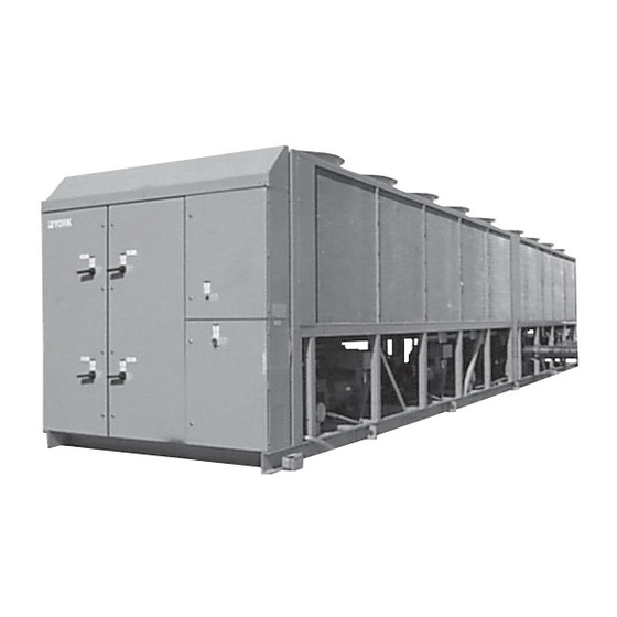
Product Description SECTION 2 – PRODUCT DESCRIPTION 1 System Fans 2 System 1 Power Panel 3 System 2 Power Panel 4 Control Panel 5 Power Entry 6 System 2 Compressor 7 Cooler (Evaporator) 8 System 4 Compressor 9 System 2 Condenser 10 Option Box 00258VIP FIG. -
Page 15: Evaporator
Evaporator Condenser 00485VIP FIG. 2 – SCREW COMPRESSOR... -
Page 16: Oil Separator/System
Product Description Oil Cooling Capacity Control Oil Separator/System Power and Control Panels Each power compartment contains:... -
Page 17: Microprocessor Controls
The control section contains: The options sections contain: Microprocessor Controls Motor Protector Module Motor Current Protection... -
Page 18: Current Overload
A switch must be pushed to the left to place the switch in the ON position. Other symbols It is recommended that a YORK Ser- vice Technician or the YORK factory be consulted before changing these settings for any reason, since damage to the compressor could result. -
Page 19: Thermal Overload
Thermal Overload unloaded compressor condition Ω loaded compressor condition Ω Ω Imbalance Current Imbalance (Loaded & Unloaded)/ Loss of Phase Improper Phase Sequence... -
Page 20: Motor Protector Dip Switch Settings
Product Description TABLE 1 – MOTOR PROTECTOR DIP SWITCH SETTING – ACROSS-THE-LINE START – 60 HZ... -
Page 21: Table 2 – Motor Protector Dip Switch Setting – Across-The-Line Start, 50 Hz
TABLE 2 – MOTOR PROTECTOR DIP SWITCH SETTING – ACROSS-THE-LINE START – 50 HZ... -
Page 22: Table 3 – Motor Protector Dip Switch Setting – Wye-Delta Start, 60 Hz
Product Description TABLE 3 – MOTOR PROTECTOR DIP SWITCH SETTING – WYE-DELTA START – 60 HZ... -
Page 23: Table 4 – Motor Protector Dip Switch Setting – Wye-Delta Start, 50 Hz
TABLE 4 – MOTOR PROTECTOR DIP SWITCH SETTING – WYE-DELTA START – 50 HZ... -
Page 24: Motor Starting
Product Description Systems 3 and 4 operate in a similar MOTOR STARTING sequence. 1 TR, 2TR, 3TR, and 4TR are NOT “timing” relays. These devices are sim- ply pilot relays identical to 1CR - 4CR. KEYPAD CONTROLS Display... -
Page 25: Entry
Entry Setpoints Single-Point Power Connection without Circuit Protection (Not available on 3 and 4 compressor Clock models) Print Program – Control Circuit Terminal Block Building Automation System (BAS) Interface ACCESSORIES AND OPTIONS Multiple Point Power Connection (Standard) Condenser Coil Protection Single-Point Power Connection with Individual Circuit Protection Black fin condenser coils... -
Page 26: Dx Cooler Options
Product Description Phenolic coated condenser coils Louvered panels and wired guards Louvered panels (condenser coils only) DX COOLER OPTIONS: 300 PSIG (21 bar) Waterside Design Working Pressure Louvered panels (full unit) enclosure 1-1/2" (38 mm) Insulation FANS High static fans: Flange Accessory SOUND REDUCTION OPTIONS Remote DX Cooler –... -
Page 27: Unit Nomenclature And Nameplate Engineering Data
5 6 7 8 11 12 13 14 15 BASE PRODUCT TYPE NOMINAL CAPACITY UNIT DESIGNATOR REFRIGERANT VOLTAGE/STARTER DESIGN/DEVELOPMENT LEVEL : 200/3/60 : YORK Tons High-Efficiency : Design Series : R-407C 0218 0685 : 230/3/60 : Chiller : Air-Cooled 0248... - Page 28 38 39 40 41 42 43 44 45 46 47 48 49 50 51 52 53 54 EVAP. FIELD CONDENSER FIELD CABINET FIELD : Aluminum : 300 PSIG DWP Waterside : Wire (Full Unit) Enc. Panels (factory) : Copper : Double Thick Insulation : Wire (Full Unit) Enc.
-
Page 29: Section 3 Handling And Storage
SECTION 3 – HANDLING AND STORAGE DELIVERY AND STORAGE INSPECTION MOVING THE CHILLER Unit must be “blocked” so that the base is not permitted to sag or bow. The unit must only be lifted by the base frame at the points provided. Never move the unit on rollers, or lift the unit using a forklift truck. -
Page 30: Unit Rigging
Handling and Storage UNIT RIGGING 88" (2250mm) CORRECT! WRONG! LD03514 FIG. 3 – UNIT RIGGING WRONG! CORRECT! LD03515 FIG. 4 – LIFTING LUGS... -
Page 31: Section 4 Installation
SECTION 4 – INSTALLATION LOCATION REQUIREMENTS INDOOR INSTALLATIONS OUTDOOR INSTALLATIONS LOCATION CLEARANCES... -
Page 32: Installation Of Vibration Isolators
Installation SHIPPING BRACES PIPEWORK CONNECTION General Requirements The clearance dimensions given are necessary to maintain good airflow and ensure correct unit operation. It The maximum flow rate and pressure is also necessary to consider access re- drop for the cooler must not be ex- quirements for safe operation and ceeded at any time. -
Page 33: Water Treatment
the quality of the water in circulation is adequate, without any dissolved gases which can cause oxidation of steel parts within the cooler. WATER TREATMENT The cooler must be protected by a strainer, prefer- ably of 30 mesh, fitted as close as possible to the liq- uid inlet connection, and provided with a means of local isolation. -
Page 34: Connection Types & Sizes
Installation CONNECTION TYPES & SIZES COOLER CONNECTIONS = 1.447 x L Where: D = minimum pipe internal diameter L = length of pipe in meters LD03521 FIG. 6 – VICTAULIC GROOVE Option Flanges DUCTWORK CONNECTION General Requirements LD03523 Weld Flange Victaulic Adapter FIG. -
Page 35: Electrical Connection
In tion (not supplied by YORK). cold weather, this could cause serious damage to the chiller due to evapora- tor freeze-up. Do not remove power... -
Page 36: Remote Emergency Stop Device
Installation Remote Emergency Stop Device Alarm Contacts CONTROL PANEL WIRING SYSTEM INPUTS Flow Switch Remote Run/Stop Remote Print Remote Setpoint Offset – Temperature VOLTS FREE CONTACTS Chilled Liquid Pump Starter Remote Setpoint Offset – Current Run Contact... -
Page 37: Power And Control Panel Layouts (Wye-Delta Typical)
POWER AND CONTROL PANEL LAYOUTS (WYE-DELTA TYPICAL) 00263VIP FIG. 8 – POWER PANEL SECTION... -
Page 38: Options Panel Layout (Typical)
Installation OPTIONS PANEL LAYOUT (TYPICAL) 00246VIP FIG. 9 – POWER PANEL SECTION (CONT’D) -
Page 39: Logic Section Layout
LOGIC SECTION LAYOUT 00247VIP PHOTOGRAPH OF LOGIC SECTION ITEM DESCRIPTION FIG. 10 – LOGIC SECTION LAYOUT... -
Page 40: Logic Section Layout With Control Panel Layout
Installation LOGIC SECTION LAYOUT WITH CONTROL PANEL LAYOUT 00248VIP FIG. 11 – LOGIC SECTION LAYOUT WITH CONTROL PANEL LAYOUT... -
Page 41: Customer Connections
CUSTOMER CONNECTIONS 00249VIP Flow Switch System No. 1 Run System No. 1 Alarm Contacts System No. 2 Run Current Chilled Liquid Circulating Pump Start Temperature System No. 2 Print Alarm Contacts Chiller Run Isolator Auxiliary Interlock LD03502 FIG. 12 – CUSTOMER CONNECTIONS... -
Page 42: Fig.13 – Customer Connections
Installation CUSTOMER CONNECTIONS 28965A FIG.13 – CUSTOMER CONNECTIONS... -
Page 43: Section 5 Commissioning
SECTION 5 – COMMISSIONING PREPARATION Commissioning of this unit should only be carried out by YORK Autho- rized personnel. The eco Microcomputer Control System Operat- ing Instructions must be read in conjunction with Fans this section. PREPARATION – POWER OFF... - Page 44 Commissioning Switch Settings Temperature Sensor(s) Control Supply The machine is now live! Programmed Options Programmed Settings Crankcase Heaters Date and Time Water System Start/Stop Schedule Setpoint and Remote Offset Flow Switch...
-
Page 45: First Time Start-Up
FIRST TIME START-UP Fan Rotation During the commissioning period there should be sufficient heat load to run the unit under stable full load op- eration to enable the unit controls, and Suction Superheat system operation to be set up correctly and a commissioning log taken. -
Page 46: Section 6 Operation
Operation SECTION 6 – OPERATION GENERAL DESCRIPTION NORMAL RUNNING AND CYCLING START-UP SHUTDOWN... -
Page 47: Section 7 Technical Data
SECTION 7 – TECHNICAL DATA – ENGLISH UNITS (60 HZ) FLOW RATE AND PRESSURE DROP CHARTS WATER PRESSURE DROP - 3 & 4 COMPRESSOR UNITS C4 C5 1000 10000 LD06102 Water Flow [GPM] MODEL NUMBER YCAS COOLER FIG. 14 – FLOW RATE AND PRESSURE DROP CHARTS – ENGLISH UNITS (60 HZ) TECHNICAL DATA –... -
Page 48: Fig. 16 – Flow Rate And Pressure Drop (Si Units, 50 Hz)
Technical Data TECHNICAL DATA – SI UNITS (50 HZ) FLOW RATE AND PRESSURE DROP CHARTS LD05883 1000 Water Flow (l/s) 3 AND 4 CIRCUIT CHILLERS MODEL NUMBER YCAS COOLER FIG. 16 – FLOW RATE AND PRESSURE DROP CHARTS – SI UNITS (50 HZ) Excessive flow, above the max L/S, will damage the evaporator. -
Page 49: Fig. 17 – Glycol Correction Factors
TECHNICAL DATA GLYCOL CORRECTION FACTORS ETHYLENE GLYCOL 1.45 1.40 1.35 1.30 1.25 1.20 1.15 1.10 1.05 ˚C A = Correction Factor PROPYLENE GLYCOL B = Mean Temperature through Cooler C = Concentration W/W ˚C LD03504 FIG. 17 – GLYCOL CORRECTION FACTORS... -
Page 50: Temperature And Flows
Technical Data TEMPERATURE AND FLOWS (60 HZ) TABLE 5 – TEMPERATURE AND FLOWS – ENGLISH UNITS, 60 HZ MODEL LEAVING WATER COOLER FLOW AIR ON TEMPERATURE (°F) (GPM) CONDENSER (°F) NUMBER YCAS MIN. MIN. MAX. MIN. 0218 0248 0268 0288 0308 0328 0358... -
Page 51: Table 7 – Temperatures And Flows – Si Units, 50 Hz
TEMPERATURE AND FLOWS (50 HZ) TABLE 7 – TEMPERATURE AND FLOWS – SI UNITS, 50 HZ MODEL LEAVING WATER COOLER FLOW AIR ON TEMPERATURE (°C) (L/S) CONDENSER (°C) NUMBER YCAS MIN. MAX. MIN. MAX. MIN. 0685 0775 0835 0905 0965 1065 1135 1215... -
Page 52: Physical Data (English Units)
Technical Data PHYSICAL DATA R-407C OPTIMIZED (60 HZ) TABLE 8 – PHYSICAL DATA – ENGLISH UNITS, 60 HZ, R-407C OPTIMIZED Unit Capacity at 44°F water & 95°F ambient, TR 208.3 234.8 257.5 272.0 291.9 310.3 347.6 377.8 406.7 Number of Independent Refrigerant Circuits Refrigerant Charge, R-407C, Ckt.-1/Ckt.-2, lbs. -
Page 53: Physical Data (Si Units)
PHYSICAL DATA R-407C OPTIMIZED (60 HZ) TABLE 9 – PHYSICAL DATA – SI UNITS, 60 HZ, R-407C OPTIMIZED Unit Capacity at 7°C water & 35°C ambient, kW 1037 1102 1235 1342 1444 Number of Independent Refrigerant Circuits Refrigerant Charge, R-407C, Ckt.-1/Ckt.-2, kg. 85/85/85 85/85/91 88/88/88... -
Page 54: Table 10 – Physical Data – Si, 50 Hz, R-407C Optimized
Technical Data PHYSICAL DATA – R-407C OPTIMIZED (50 HZ) TABLE 10 – PHYSICAL DATA – SI UNITS, 50 HZ, R-407C OPTIMIZED Unit Capacity at 7°C water & 35°C ambient, kW 1056 1125 1194 Number of Independent Refrigerant Circuits Refrigerant Charge, R-407C, Ckt.-1/Ckt.-2/Ckt.-3/Ckt.-4, kg 78/78/91 88/88/88 91/88/88... -
Page 55: Operating Limitations & Sound Power Data
OPERATING LIMITATIONS AND SOUND POWER DATA (60 HZ) TABLE 11 – OPERATING LIMITATIONS, 60 HZ ENGLISH UNITS LEAVING CHILLED LIQUID TEMP ( °F) 40.1 CHILLED WATER TEMP DIFFERENCE ( °F) WATER SIDE PRESSURE (PSIG) — REFRIGERANT SIDE PRESSURE (PSIG) — COOLER FLOW MODEL GALLONS/MINUTE... -
Page 56: Table 13 – Operating Limitations – Si Units 60 Hz
Technical Data OPERATING LIMITATIONS AND SOUND POWER DATA (60 HZ) TABLE 13 – OPERATING LIMITATIONS, 60 HZ SI UNITS M A X LEAVING CHILLED LIQUID TEMP ( °C) CHILLED WATER TEMP DIFFERENCE ( °C) WATER SIDE PRESSURE (BAR) – REFRIGERANT SIDE PRESSURE (BAR) –... -
Page 57: Table 15 – Operating Limitations – Si Units 50 Hz
OPERATING LIMITATIONS AND SOUND POWER DATA (50 HZ) TABLE 15 – OPERATING LIMITATIONS, 50 HZ SI UNITS MIN. MAX. LEAVING CHILLED LIQUID TEMP ( °C) CHILLED WATER TEMP DIFFERENCE ( °C) WATER SIDE PRESSURE (BAR) – REFRIGERANT SIDE PRESSURE (BAR) –... -
Page 58: Electrical Data (60 Hz)
Technical Data ELECTRICAL DATA (60 HZ) MULTIPLE POINT POWER SUPPLY CONNECTION – 3 & 4 COMPRESSOR UNITS (SEE FIG. 18 or 19) (Two Field-Provided Power Supply Circuits To The Chiller. Field Connections to Factory-Provided Terminal Block (Std) or Disconnects (Opt) in the Options Panel. - Page 59 11, 12 2, 9 3, 5 4, 6 # 2 - 4/0 #4 - 300 — — — 21.0 # 2 - 4/0 # 2 - 4/0 — — — 29.0 # 2 - 4/0 # 2 - 4/0 — —...
-
Page 60: Optional Single-Point Power Supply Connection With Individual System Circuit Breakers (60 Hz)
Technical Data ELECTRICAL DATA (60 HZ) OPTIONAL SINGLE-POINT POWER SUPPLY CONNECTION WITH INDIVIDUAL SYSTEM CIRCUIT BREAKERS – 3 & 4 COMPRESSOR UNITS (SEE FIG. 20) (One Field-Provided Power Supply Circuit to the chiller. Field connections to Factory-Provided Terminal Block (standard) or Non-Fused Disconnect (option) in Options Panel. -
Page 61: Table 20 – Control Power Supply (Units With Standard Control Circuit Transformers)
11, 12 2, 9 3, 5 4, 6 (2) 1/0 - 300 (2) 250-500 21.0 (2) 1/0 - 300 (2) 250-500 29.0 (2) # 2 - 4/0 (2) 3/0 - 250 25.9 (2) 2/0 - 500 (2) 250-500 21.0 (2) 1/0 - 300 (2) 250-500 29.0 (2) # 2 - 4/0... -
Page 62: Electrical Notes (60 Hz)
Technical Data ELECTRICAL NOTES (60 HZ) NOTES 1995 copper connectors LEGEND... -
Page 63: Power Connection Options (60 Hz)
POWER CONNECTION OPTIONS (60 HZ) 3 & 4 COMPRESSOR POWER CONNECTION OPTIONS Suitable for: Across the Line Start Control Power Wiring As Shown On The Two Compressor Diagrams Field Supply #2 See Note 3 Field Supply #1 LD05552 FIG. 18 – MULTIPLE POINT POWER SUPPLY CONNECTION Suitable for: Y - ∆... -
Page 64: Fig. 20 – Optional Single-Point Power Supply Connection With Individual System Circuit Breakers
Technical Data POWER CONNECTION OPTIONS (60 HZ) Suitable for: Y - ∆ Start and Across the Line Start Field Supply See Note 3 LD05554 FIG. 20 – OPTIONAL SINGLE-POINT POWER SUPPLY CONNECTION WITH INDIVIDUAL SYSTEM CIRCUIT BREAKERS NOTES:... -
Page 66: Electrical Data (50 Hz)
Technical Data ELECTRICAL DATA (50 HZ) MULTIPLE POINT POWER SUPPLY CONNECTION – 3 & 4 COMPRESSOR UNITS (SEE FIG. 21 OR 22) (Two Field-Provided Power Supply Circuits to the Chiller. Field Connections to Factory-Provided Terminal Block (Std) or Disconnects (Opt) in the Options Panel. Factory Wired Terminal Blocks or Individual System Circuit Breakers* (opt ) in each of the two Motor Control Centers.) TABLE 21 –... - Page 67 11, 12 3, 5 4, 6 (1) # 2 - 4/0 (1) # 2 - 4/0 —- —- —- (1) # 2 - 4/0 (1) #4 - 300 —- —- —- (1) # 2 - 4/0 (1) #4 - 300 —- —- —-...
-
Page 68: Table 23 – Control Power Supply (Units Without Standard Control Circuit Transformers)
Technical Data ELECTRICAL DATA (50 HZ) TABLE 23 – CONTROL POWER SUPPLY (UNITS WITHOUT STANDARD CONTROL CIRCUIT TRANSFORMERS) CONTROL MAX DUAL NON-FUSED NO. OF POWER (MAX LOAD ELEMENT DISCONNECT COMPRESSORS SUPPLY CURRENT) FUSE SIZE SWITCH SIZE TABLE 24 – CONTROL POWER SUPPLY (UNITS WITH STANDARD CONTROL CIRCUIT TRANSFORMERS) CONTROL RECOMMENDED NON-FUSED... -
Page 69: Electrical Notes (50 Hz)
ELECTRICAL NOTES (50 HZ) NOTES 1995 copper connectors TABLE 25 – COMPRESSOR DATA -50 -58 80 105 135 118 TABLE 26 – FAN DATA (-46) 1.57 18.0 46.3... -
Page 70: Power Connection Options (50 Hz)
Technical Data POWER CONNECTION OPTIONS (50 HZ) STYLE “F” 3 AND 4 COMPRESSOR POWER WIRING CONNECTIONS Suitable for: Across the Line Start Field Supply #2 Field Supply #1 LD05558 FIG. 21 – MULTIPLE POINT POWER SUPPLY CONNECTION Suitable for: Y - ∆ Start and Across the Line Start CE Mark Field Supply #2... -
Page 71: Fig. 23 – Optional Single-Point Power Supply Connection With Individual System Circuit Breakers
POWER CONNECTION OPTIONS (50 HZ) STYLE “F” 3 AND 4 COMPRESSOR POWER WIRING CONNECTIONS Suitable for: Y - ∆ Start and Across the Line Start Field Supply See Note 3 LD05554 FIG. 23 – OPTIONAL SINGLE-POINT POWER SUPPLY CONNECTION WITH INDIVIDUAL SYSTEM CIRCUIT BREAKERS NOTES:... -
Page 72: Elementary Diagram
Technical Data ELEMENTARY DIAGRAM LD04172A FIG. 24 – ELEMENTARY DIAGRAM – ACROSS-THE-LINE START... - Page 73 ELEMENTARY DIAGRAM LD04172B FIG. 24 – ELEMENTARY DIAGRAM – ACROSS-THE-LINE START (CONT’D)
-
Page 74: Wiring Diagrams–Across-The-Line Start And Wye-Delta Start
(Class 2) Connections. See Note 2 switch (FSLW). See Note 3 for contact rating and wiring Terminal Block for YORK Connections Only specifications. Also refer to cautions on page 79A. Wiring and Components by YORK 5. -
Page 75: Standard 3 Compressor Power Supplies Wye-Delta Start
STANDARD 3 COMPRESSOR POWER SUPPLIES WYE-DELTA START (PRESENT ON CERTAIN MODEL CHILLERS) (PRESENT ON CERTAIN MODEL CHILLERS) (PRESENT ON CERTAIN MODEL CHILLERS) (PRESENT ON CERTAIN MODEL CHILLERS) LD04174 FIG. 26 – STANDARD 3 COMPRESSOR POWER SUPPLIES - WYE-DELTA START... -
Page 76: Wiring Diagram – Across-The Line Start
Technical Data WIRING DIAGRAM ACROSS-THE-LINE START (PRESENT ON CERTAIN MODEL CHILLERS) (PRESENT ON CERTAIN MODEL CHILLERS) (PRESENT ON CERTAIN MODEL CHILLERS) (PRESENT ON CERTAIN MODEL CHILLERS) LD04173 FIG. 27 – ELEMENTARY DIAGRAM – ACROSS-THE-LINE START... -
Page 78: Standard Compressor Power Supplies – Across-The Line Start And Wye-Delta Start
Technical Data STANDARD COMPRESSOR POWER SUPPLIES ACROSS-THE-LINE START & WYE-DELTA START LD07626 FIG. 28 – ELEMENTARY DIAGRAM... - Page 79 Any contacts connected to flow switch inputs or BAS inputs on terminals 13 - 19 or TB3, or any other terminals, must be sup- pressed with a YORK P/N 031- 00808-000 suppressor across the relay/contactor coil. Control wiring connected to...
- Page 80 FORM 201.18-NM9 (602) FORM 201.18-NM9 (602) CONNECTION DIAGRAM FIG. 29 – CONNECTION DIAGRAM LD04178 YORK INTERNATIONAL YORK INTERNATIONAL...
- Page 81 LD04179...
-
Page 82: Connection Diagram
Technical Data CONNECTION DIAGRAM Box Information continued from page 81 FIG. 29 – CONNECTION DIAGRAM (CONT’D) LD04180... - Page 83 Box Information continued from page 82 LD04181...
-
Page 84: Connection Diagram – Electrical Box
Technical Data FIG. 29 LEGEND (PAGES 79B, 80, 81) CONNECTION DIAGRAM ELECTRIC BOX DXST DIRECT DRIVE FIG. 30 – CONNECTION DIAGRAM – ELECTRIC BOX DXST DIRECT DRIVE LD03281... -
Page 85: Fig. 31 – Connection Diagram – Electrical Box
CONNECTION DIAGRAM - ELECTRICAL BOX YCAS0218EB - YCAS0328EB AND YCAS0685EB - YCAS0965EB STANDARD & REMOTE EVAP. UNITS FIG. 31 – CONNECTION DIAGRAM – ELECTRICAL BOX... - Page 86 Technical Data CONNECTION DIAGRAM - ELECTRICAL BOX YCAS0218EB - YCAS0328EB AND YCAS0685EB - YCAS0965EB STANDARD & REMOTE EVAP. UNITS FIG. 31 – CONNECTION DIAGRAM – ELECTRICAL BOX (CONT’D)
-
Page 87: Elementary Diagram Dxst Direct Drive Control Circuit
ELEMENTARY DIAGRAM DXST DIRECT DRIVE CONTROL CIRCUIT LD04177 FIG. 32 – ELEMENTARY DIAGRAM, DXST DIRECT DRIVE - CONTROL CIRCUIT... - Page 88 Technical Data ELEMENTARY DIAGRAM DXST DIRECT DRIVE CONTROL CIRCUIT LD04373 FIG. 32 – ELEMENTARY DIAGRAM, DXST DIRECT DRIVE - CONTROL CIRCUIT (CONT’D)
- Page 89 ELEMENTARY DIAGRAM DXST DIRECT DRIVE CONTROL CIRCUIT DETAIL "C" SEE INSTALLATION, OPERATION AND MAINTENANCE MANUAL FOR JUMPER OF CONDENSER FANS FOR CHILLER MODEL LD07065 FIG. 32 – ELEMENTARY DIAGRAM, DXST DIRECT DRIVE - CONTROL CIRCUIT (CONT’D)
-
Page 90: Connection Diagram System Wiring – Standard And Remote Evap. Units
Technical Data CONNECTION DIAGRAM SYSTEM WIRING STANDARD & REMOTE EVAP. UNITS LD04184 FIG. 33 – CONNECTION DIAGRAM SYSTEM WIRING... - Page 91 CONNECTION DIAGRAM SYSTEM WIRING STANDARD & REMOTE EVAP. UNITS LD04185 FIG. 33 – CONNECTION DIAGRAM SYSTEM WIRING (CONT’D)
-
Page 92: Elementary Diagram Dxst Direct Drive Power Circuit
Technical Data ELEMENTARY DIAGRAM DXST DIRECT DRIVE POWER CIRCUIT FIG. 34 – ELEMENTARY DIAGRAM – DXST DIRECT DRIVE – POWER CIRCUIT... - Page 93 ELEMENTARY DIAGRAM DXST DIRECT DRIVE POWER CIRCUIT FIG. 34 – ELEMENTARY DIAGRAM – DXST DIRECT DRIVE – POWER CIRCUIT (CONT’D)
-
Page 94: Wiring Diagram –Across-The -Line Start And Wye-Delta Start
24VDC. (Gold contacts recommended.) Con- (Class 2) Connections. See Note 2 trol Wiring must not be run in the same conduit with any Terminal Block for YORK Connections Only line voltage wiring. Wiring and Components by YORK 4. To cycle unit ON and OFF automatically with contact... -
Page 95: Standard 4 Compressor Power Supplies Wye-Delta Start
STANDARD 4 COMPRESSOR POWER SUPPLIES WYE-DELTA START LD07627 FIG. 36 – STANDARD 4-COMPRESSOR POWER SUPPLIES - WYE-DELTA START... -
Page 96: Standard Compressor Power Supplies – Across-The-Line Start
Technical Data STANDARD 4-COMPRESSOR POWER SUPPLIES ACROSS-THE-LINE START (YCAS0358EB-0418EB AND YCAS1065EB-1215EB) LD04261 FIG. 37 – STANDARD 4-COMPRESSOR POWER SUPPLIES - ACROSS-THE-LINE START... -
Page 98: Standard Compressor Power Supplies
Technical Data STANDARD COMPRESSOR POWER SUPPLIES (YCAS0358EB - YCAS0418EB AND YCAS1065EB - YCAS1215EB) ACROSS-THE-LINE START & WYE-DELTA START FIG. 38 – STANDARD COMPRESSOR POWER SUPPLIES - ACROSS-THE-LINE START AND WYE-DELTA START... - Page 99 FORM 201.18-NM9 (602) FORM 201.18-NM9 (602) LD07629 YORK INTERNATIONAL YORK INTERNATIONAL...
- Page 100 FORM 201.18-NM9 (602) FORM 201.18-NM9 (602) CONNECTION DIAGRAM – SYSTEMS 1 & 2 FIG. 39 – CONNECTION DIAGRAM – ACROSS-THE-LINE AND WYE-DELTA START, SYSTEMS 1 & 2 YORK INTERNATIONAL YORK INTERNATIONAL...
- Page 101 Any contacts connected to flow switch inputs or BAS inputs on terminals 13 - 19 or TB3, or any other terminals, must be suppressed with a YORK P/N 031-00808-000 suppressor across the relay/contactor coil. Control wiring connected to the con- trol panel should never be run in the same conduit with power wiring.
-
Page 102: Connection Diagram Systems 1 & 2
Technical Data CONNECTION DIAGRAM – SYSTEMS 3 & 4 FIG. 40 – CONNECTION DIAGRAM – ACROSS-THE-LINE AND WYE-DELTA START, SYSTEMS 3 & 4... - Page 103 FORM 201.18-NM9 (602) FORM 201.18-NM9 (602) LD04267 103A YORK INTERNATIONAL YORK INTERNATIONAL...
-
Page 104: Connection Diagram – Electrical Box
FORM 201.18-NM9 (602) FORM 201.18-NM9 (602) CONNECTION DIAGRAM – ELECTRICAL BOX (YCAS0358EB - YCAS0418EB AND YCAS1065EB - YCAS1215EB) STANDARD & REMOTE EVAP. UNITS This page intentionally left blank. FIG. 41 – CONNECTION DIAGRAM – ELECTRICAL BOX 103B YORK INTERNATIONAL YORK INTERNATIONAL... - Page 105 CONNECTION DIAGRAM – ELECTRICAL BOX (YCAS0358EB-0418EB AND YCAS1065EB-1215EB) STANDARD & REMOTE EVAP. UNITS FIG. 41 – CONNECTION DIAGRAM – ELECTRICAL BOX (CONT’D)
-
Page 106: Elementary Diagram Dxst Direct Drive Control Circuit
Technical Data ELEMENTARY DIAGRAM DXST DIRECT DRIVE CONTROL CIRCUIT LD04177 FIG. 42 – ELEMENTARY DIAGRAM, DXST DIRECT DRIVE - CONTROL CIRCUIT... - Page 107 ELEMENTARY DIAGRAM DXST DIRECT DRIVE CONTROL CIRCUIT LD04695 FIG. 42 – ELEMENTARY DIAGRAM, DXST DIRECT DRIVE - CONTROL CIRCUIT (CONT’D)
- Page 108 Technical Data ELEMENTARY DIAGRAM DXST DIRECT DRIVE CONTROL CIRCUIT DETAIL "C" SEE INSTALLATION, OPERATION AND MAINTENANCE MANUAL FOR NUMBER OF CONDENSER FANS FOR CHILLER MODELS LD04757 FIG. 42 – ELEMENTARY DIAGRAM, DXST DIRECT DRIVE - CONTROL CIRCUIT (CONT’D)
-
Page 109: Connection Diagram System Wiring – Standard And Remote Evap. Units
CONNECTION DIAGRAM SYSTEM WIRING STANDARD & REMOTE EVAP. UNITS LD07263 FIG. 43 – CONNECTION DIAGRAM SYSTEM WIRING – STANDARD AND REMOTE EVAP. UNITS... - Page 110 Technical Data CONNECTION DIAGRAM SYSTEM WIRING STANDARD & REMOTE EVAP. UNITS LD04270 FIG. 43 – CONNECTION DIAGRAM SYSTEM WIRING – STANDARD AND REMOTE EVAP. UNITS (CONT’D)
-
Page 111: Compressor Terminal Box – Systems 1- 4
COMPRESSOR TERMINAL BOX SYSTEMS 1 THROUGH 4 LD04271 FIG. 44 – COMPRESSOR TERMINAL BOX, SYSTEMS 1-4... -
Page 112: Dimensions
Technical Data DIMENSIONS – YCAS0218EB - 0268EB (ENGLISH) (60 HZ) 7" CONTROL OPENING 42" 28" (9" HIGH) 2" CONTROL ENTRY (12) 1/2" 2" 12" CONDUIT K.O.'S 31 1/2" 4 3/4" POWER 2" TYP. 9" OPENING (21" HIGH) VIEW B-B VIEW C-C 7 1/2"... - Page 113 DIMENSIONS – YCAS0218EB - 0268EB (ENGLISH) (60 HZ) 5/8" DIA. MOUNTING HOLES (TYP.) 1 1/4" 30" SYS. 1 SYS. 3 POWER ELEMENTS FOR SYS. 1&3 APPROX. OPERATING WEIGHT 88" 30" DISTRIBUTION (LB) POWER ELEMENTS FOR SYS. 2 SYS. 2 1 1/4" CONTROL PANEL ORIGIN 31 3/4"...
-
Page 114: Ycas0288Eb (English) (60 Hz)
Technical Data DIMENSIONS – YCAS0288EB (ENGLISH) (60 HZ) 7" CONTROL OPENING 42" 28" (9" HIGH) 2" CONTROL ENTRY (12) 1/2" 2" 12" CONDUIT K.O.'S 31 1/2" 4 3/4" POWER 2" TYP. 9" OPENING (21" HIGH) VIEW B-B 7 1/2" VIEW C-C MICROCOMPUTER CONTROL CENTER OPTIONS PANEL... - Page 115 DIMENSIONS – YCAS0288EB (ENGLISH) (60 HZ) 5/8" DIA. MOUNTING HOLES (TYP.) 1 1/4" 30" SYS. 1 SYS. 3 POWER ELEMENTS APPROX. OPERATING WEIGHT FOR SYS. 1&3 88" DISTRIBUTION (LB) 30" POWER ELEMENTS FOR SYS. 2 SYS. 2 1 1/4" CONTROL PANEL ORIGIN 31 3/4"...
-
Page 116: Ycas0308Eb (English) (60 Hz)
Technical Data DIMENSIONS – YCAS0308EB (ENGLISH) (60 HZ) 7" CONTROL OPENING 42" 28" (9" HIGH) 2" CONTROL ENTRY (12) 1/2" 2" 12" CONDUIT K.O.'S 31 1/2" 4 3/4" POWER 2" TYP. 9" OPENING (21" HIGH) VIEW B-B VIEW C-C 7 1/2" MICROCOMPUTER CONTROL CENTER OPTIONS PANEL... - Page 117 DIMENSIONS – YCAS0308EB (ENGLISH) (60 HZ) 5/8" DIA. MOUNTING HOLES (TYP.) 1 1/4" 30" 30" SYS. 1 SYS. 3 APPROX. OPERATING WEIGHT POWER ELEMENTS DISTRIBUTION (LB) 88" 88" FOR SYS. 1&3 30" 30" POWER ELEMENTS FOR SYS. 2 SYS. 2 1 1/4"...
-
Page 118: Ycas0328Eb (English) (60 Hz)
Technical Data DIMENSIONS – YCAS0328EB (ENGLISH) (60 HZ) 7" CONTROL OPENING 42" 28" (9" HIGH) 2" CONTROL ENTRY (12) 1/2" 2" 12" CONDUIT K.O.'S 31 1/2" 4 3/4" POWER 2" TYP. 9" OPENING (21" HIGH) VIEW B-B VIEW C-C 7 1/2" MICROCOMPUTER CONTROL CENTER OPTIONS PANEL... - Page 119 DIMENSIONS – YCAS0328EB (ENGLISH) (60 HZ) 5/8" DIA. MOUNTING HOLES (TYP.) 1 1/4" 30" SYS. 3 SYS. 1 POWER ELEMENTS APPROX. OPERATING WEIGHT 88" FOR SYS. 1&3 DISTRIBUTION (LB) 30" POWER ELEMENTS FOR SYS. 2 SYS. 2 1 1/4" CONTROL PANEL ORIGIN 57 3/16"...
-
Page 120: Ycas0358Eb (English) (60 Hz)
Technical Data DIMENSIONS – YCAS0358EB (ENGLISH) (60 HZ) 7" CONTROL OPENING 42" 28" (9" HIGH) 2" CONTROL ENTRY (12) 1/2" 2" 12" CONDUIT K.O.'S 31 1/2" 4 3/4" POWER 2" TYP. 9" OPENING (21" HIGH) VIEW B-B VIEW C-C 7 1/2" MICROCOMPUTER CONTROL CENTER OPTIONS PANEL... - Page 121 DIMENSIONS – YCAS0358EB (ENGLISH) (60 HZ) 5/8" DIA. MOUNTING HOLES (TYP.) 1 1/4" 30" SYS. 1 SYS. 3 POWER ELEMENTS 88" APPROX. OPERATING WEIGHT FOR SYS. 1&3 30" DISTRIBUTION (LB) POWER ELEMENTS FOR SYS. 2&4 SYS. 2 SYS. 4 1 1/4" CONTROL PANEL ORIGIN 31 3/4"...
-
Page 122: Ycas0398Eb - 0418Eb (English) (60 Hz)
Technical Data DIMENSIONS – YCAS0398EB - 0418EB (ENGLISH) (60 HZ) 7" CONTROL OPENING 42" 28" (9" HIGH) 2" CONTROL ENTRY (12) 1/2" 2" 12" CONDUIT K.O.'S 31 1/2" 4 3/4" POWER 2" TYP. 9" OPENING (21" HIGH) VIEW B-B VIEW C-C 7 1/2"... - Page 123 DIMENSIONS – YCAS0398EB - 0418EB (ENGLISH) (60 HZ) 5/8" DIA. MOUNTING HOLES (TYP.) 1 1/4" 30" SYS. 1 SYS. 3 POWER ELEMENTS 88" APPROX. OPERATING WEIGHT FOR SYS. 1&3 30" POWER ELEMENTS DISTRIBUTION (LB) FOR SYS. 2&4 SYS. 2 SYS. 4 1 1/4"...
-
Page 124: Ycas0218Eb - 0268Eb (Si) (60 Hz)
Technical Data DIMENSIONS – YCAS0218EB - 0268EB (SI) (60 HZ) All dimensions are in mm unless otherwise noted. CONTROL 1067 OPENING (229 HIGH) CONTROL ENTRY (12) 13 CONDUIT K.O.'S POWER 51 TYP. OPENING (533 HIGH) VIEW B-B VIEW C-C MICROCOMPUTER CONTROL CENTER OPTIONS PANEL CONTROL... - Page 125 DIMENSIONS – YCAS0218EB - 0268EB (SI) (60 HZ) 16 DIA. MOUNTING HOLES (TYP.) SYS. 1 SYS. 3 POWER ELEMENTS APPROX. OPERATING WEIGHT FOR SYS. 1&3 2235 DISTRIBUTION (KG) POWER ELEMENTS FOR SYS. 2 SYS. 2 CONTROL PANEL ORIGIN 1453 1453 1453 1229 1400...
-
Page 126: Ycas0288Eb (Si) (60 Hz)
Technical Data DIMENSIONS – YCAS0288EB (SI) (60 HZ) All dimensions are in mm unless otherwise noted. CONTROL 1067 OPENING (229 HIGH) CONTROL ENTRY (12) 13 CONDUIT K.O.'S POWER 51 TYP. OPENING (533 HIGH) VIEW B-B VIEW C-C MICROCOMPUTER CONTROL CENTER OPTIONS PANEL CONTROL TRANSFORMER... - Page 127 DIMENSIONS – YCAS0288EB (SI) (60 HZ) 16 DIA. MOUNTING HOLES (TYP.) SYS. 1 SYS. 3 POWER ELEMENTS APPROX. OPERATING WEIGHT 2235 FOR SYS. 1&3 DISTRIBUTION (KG) POWER ELEMENTS FOR SYS. 2 SYS. 2 CONTROL PANEL ORIGIN 1453 1453 1453 1229 1400 VIEW D-D CENTER OF GRAVITY (Alum.)
-
Page 128: Ycas0308Eb (Si) (60 Hz)
Technical Data DIMENSIONS – YCAS0308EB (SI) (60 HZ) All dimensions are in mm unless otherwise noted. CONTROL 1067 OPENING (229 HIGH) CONTROL ENTRY (12) 13 CONDUIT K.O.'S POWER 51 TYP. OPENING (533 HIGH) VIEW B-B VIEW C-C MICROCOMPUTER CONTROL CENTER OPTIONS PANEL CONTROL TRANSFORMER... - Page 129 DIMENSIONS – YCAS0308EB (SI) (60 HZ) 16 DIA. MOUNTING HOLES (TYP.) SYS. 1 SYS. 3 APPROX. OPERATING WEIGHT POWER ELEMENTS DISTRIBUTION (KG) 2235 2235 FOR SYS. 1&3 POWER ELEMENTS FOR SYS. 2 SYS. 2 CONTROL PANEL ORIGIN ORIGIN 1453 1453 1453 1431 2417...
-
Page 130: Ycas0328Eb (Si) (60 Hz)
Technical Data DIMENSIONS – YCAS0328EB (SI) (60 HZ) All dimensions are in mm unless otherwise noted. CONTROL 1067 OPENING (229 HIGH) CONTROL ENTRY (12) 13 CONDUIT K.O.'S POWER 51 TYP. OPENING (533 HIGH) VIEW B-B VIEW C-C MICROCOMPUTER CONTROL CENTER OPTIONS PANEL CONTROL TRANSFORMER... - Page 131 DIMENSIONS – YCAS0328EB (SI) (60 HZ) 16 DIA. MOUNTING HOLES (TYP.) SYS. 1 SYS. 3 POWER ELEMENTS APPROX. OPERATING WEIGHT 2235 FOR SYS. 1&3 DISTRIBUTION (KG) POWER ELEMENTS FOR SYS. 2 SYS. 2 CONTROL PANEL 1453 1453 1453 1431 1413 1422 1422 ORIGIN...
-
Page 132: Ycas0358Eb (Si) (60 Hz)
Technical Data DIMENSIONS – YCAS0358EB (SI) (60 HZ) All dimensions are in mm unless otherwise noted. CONTROL 1067 OPENING (229 HIGH) CONTROL ENTRY (12) 13 CONDUIT K.O.'S POWER 51 TYP. OPENING (533 HIGH) VIEW B-B VIEW C-C MICROCOMPUTER CONTROL CENTER OPTIONS PANEL CONTROL TRANSFORMER... - Page 133 DIMENSIONS – YCAS0358EB (SI) (60 HZ) 16 DIA. MOUNTING HOLES (TYP.) SYS. 1 SYS. 3 POWER ELEMENTS 2235 FOR SYS. 1&3 APPROX. OPERATING WEIGHT POWER ELEMENTS DISTRIBUTION (KG) FOR SYS. 2&4 SYS. 2 SYS. 4 CONTROL PANEL 1453 1453 1453 1422 1422 1422...
-
Page 134: Ycas0398Eb - 0418Eb (Si) (60 Hz)
Technical Data DIMENSIONS – YCAS0398EB - 0418EB (SI) (60 HZ) All dimensions are in mm unless otherwise noted. CONTROL OPENING 1067 (229 HIGH) CONTROL ENTRY (12) 13 CONDUIT K.O.'S POWER 51 TYP. OPENING (533 HIGH) VIEW B-B VIEW C-C MICROCOMPUTER CONTROL CENTER OPTIONS PANEL CONTROL... - Page 135 DIMENSIONS – YCAS0398EB - 0418EB (SI) (60 HZ) 16 DIA. MOUNTING HOLES (TYP.) SYS. 1 SYS. 3 POWER ELEMENTS 2235 APPROX. OPERATING WEIGHT FOR SYS. 1&3 POWER ELEMENTS DISTRIBUTION (KG) FOR SYS. 2&4 SYS. 2 SYS. 4 CONTROL PANEL ORIGIN 1453 1453 1453...
-
Page 136: Ycas0685Eb (Si) (50 Hz)
Technical Data DIMENSIONS – YCAS0685EB (SI) (50 HZ) All dimensions are in mm unless otherwise noted. CONTROL 1067 OPENING (229 HIGH) CONTROL ENTRY (12) 13 CONDUIT K.O.'S POWER 51 TYP. OPENING (533 HIGH) VIEW B-B VIEW C-C LD05569 MICRO-COMPUTER CONTROL CENTER OPTIONS PANEL CONTROL TRANSFORMER... - Page 137 DIMENSIONS – YCAS0685EB (SI) (50 HZ) 16 DIA. MOUNTING HOLES (TYP.) SYS. 1 SYS. 3 POWER ELEMENTS FOR SYS. 1&3 2235 POWER ELEMENTS FOR SYS. 2 SYS. 2 CONTROL PANEL ORIGIN 1453 1453 1453 1229 LD05572 VIEW D-D CENTER OF GRAVITY (Alum.) CENTER OF GRAVITY (Copper) YCAS YCAS...
-
Page 138: Ycas0775Eb - 0905Eb (Si) (50 Hz)
Technical Data DIMENSIONS – YCAS0775EB - 0905EB (SI) (50 HZ) All dimensions are in mm unless otherwise noted. CONTROL 1067 OPENING (229 HIGH) CONTROL ENTRY (12) 13 CONDUIT K.O.'S POWER 51 TYP. OPENING (533 HIGH) VIEW B-B VIEW C-C LD05573 MICRO-COMPUTER CONTROL CENTER OPTIONS PANEL... - Page 139 DIMENSIONS – YCAS0775EB - 0905EB (SI) (50 HZ) 16 DIA. MOUNTING HOLES (TYP.) SYS. 1 SYS. 3 POWER ELEMENTS FOR SYS. 1&3 2235 POWER ELEMENTS FOR SYS. 2 SYS. 2 CONTROL PANEL ORIGIN 1453 1453 1453 1229 1400 VIEW D-D LD05576 CENTER OF GRAVITY (Alum.) CENTER OF GRAVITY (Copper)
-
Page 140: Ycas0965Eb (Si) (50 Hz)
Technical Data DIMENSIONS – YCAS0965EB (SI) (50 HZ) All dimensions are in mm unless otherwise noted. CONTROL 1067 OPENING (229 HIGH) CONTROL ENTRY (12) 13 CONDUIT K.O.'S POWER 51 TYP. OPENING (533 HIGH) VIEW B-B VIEW C-C LD05585 MICRO-COMPUTER CONTROL CENTER OPTIONS PANEL CONTROL TRANSFORMER... - Page 141 DIMENSIONS – YCAS0965EB (SI) (50 HZ) 16 DIA. MOUNTING HOLES (TYP.) SYS. 1 SYS. 3 POWER ELEMENTS FOR SYS. 1&3 2235 POWER ELEMENTS FOR SYS. 2 SYS. 2 CONTROL PANEL ORIGIN 1453 1453 1453 1431 1413 1422 1422 VIEW D-D LD05587 CENTER OF GRAVITY (Alum.) CENTER OF GRAVITY (Copper)
-
Page 142: Ycas1065Eb - 1215Eb (Si) (50 Hz)
Technical Data DIMENSIONS – YCAS1065EB - 1215EB (SI) (50 HZ) All dimensions are in mm unless otherwise noted. CONTROL OPENING 1067 (229 HIGH) CONTROL ENTRY (12) 13 CONDUIT K.O.'S POWER 51 TYP. OPENING (533 HIGH) VIEW B-B VIEW C-C LD05589 MICRO-COMPUTER CONTROL CENTER OPTIONS PANEL... - Page 143 DIMENSIONS – YCAS1065EB - 1215EB (SI) (50 HZ) 16 DIA. MOUNTING HOLES (TYP.) SYS. 1 SYS. 3 POWER ELEMENTS FOR SYS. 1&3 2235 POWER ELEMENTS FOR SYS. 2&4 SYS. 2 SYS. 4 CONTROL PANEL ORIGIN 1453 1453 1453 1422 1422 1422 VIEW D-D LD05591...
-
Page 144: Clearances
Technical Data CLEARANCES (1.3 m) (2 m) LD04841 Notes: No obstructions allowed above the unit. Only one adjacent wall may be higher than the unit. Adjacent units should be 10 feet (3 meters) apart. FIG. 61 – CLEARANCES... -
Page 145: Weight Distribution And Isolator Mounting Positions (60 Hz)
WEIGHT DISTRIBUTION AND ISOLATOR MOUNTING POSITIONS (60 HZ) Aluminium Fin and Black Fin Condenser Coils TABLE 27 – ALUMINUM FIN WEIGHT DISTRIBUTION BY MODEL (LBS.) 1,851 1,720 2,050 1,262 1,351 1,126 1,851 1,924 2,333 1,434 2,123 1,706 —- —- —- —- 20,732 1,904... -
Page 146: Table 29 – Aluminum Fins – Neoprene Mount Selection - Vmc Type Rd-X
Technical Data WEIGHT DISTRIBUTION AND ISOLATOR MOUNTING POSITIONS (60 HZ) Aluminium Fin and Black Fin Condenser Coils TABLE 29 – ALUMINUM FINS, NEOPRENE MOUNT SELECTION- VMC TYPE RD-X (SEE PAGE 151) 60 Hz YCAS0218 -4 RED -4 RED -4 RED -4 BLK -4 BLK -4 BLK -4 RED -4 RED -4 GRN -4 RED -4 RED -4 RED —- —- —-... -
Page 147: Table 32 – Copper Fin Weight Distribution (Lbs.)
WEIGHT DISTRIBUTION AND ISOLATOR MOUNTING POSITIONS (60 HZ) Copper Fin Coils (or Aluminum Fin with Optional Silencer Ki TABLE 32 – COPPER FIN (OR ALUMINUM FIN WITH OPTIONAL SILENCER KIT) WEIGHT DISTRIBUTION BY MODEL (LBS.) Total 1,971 1,902 2,214 1,425 1,504 1,287 1,971 2,107 2,480 1,615 2,295 1,849 —- —- —-... - Page 148 Technical Data WEIGHT DISTRIBUTION AND ISOLATOR MOUNTING POSITIONS (60 HZ) Copper Fin Coils (or Aluminum Fin with Optional Silencer Ki TABLE 34 – COPPER FINS (OR ALUMINUM FIN WITH OPTIONAL SILENCER KIT), NEOPRENE MOUNT SELECTION – VMC TYPE RD-X (SEE PAGE 151) 60 Hz YCAS0218 -4 RED -4 RED -4 RED -4 BLK -4 RED -4 BLK -4 RED -4 RED -4 GRN -4 RED -4 GRN -4 RED...
- Page 149 WEIGHT DISTRIBUTION AND ISOLATOR MOUNTING POSITIONS (60 HZ) Copper Fin Coils with Optional Silencer Kit TABLE 37 – COPPER FIN WITH OPTIONAL SILENCER KIT WEIGHT DISTRIBUTION BY MODEL (LBS.) 2,121 2,052 2,349 1,590 1,681 1,530 2,121 2,257 2,600 1,795 2,499 2,065 —- —- —-...
- Page 150 Technical Data WEIGHT DISTRIBUTION AND ISOLATOR MOUNTING POSITIONS (60 HZ) Copper Fin Coils with Optional Silencer Kit TABLE 39 – COPPER FINS WITH OPTIONAL SILENCER KIT, NEOPRENE MOUNT SELECTION - VMC TYPE RD-X (SEE PAGE 151) 60 Hz YCAS0218 -4 RED -4 GRN -4 GRN -4 RED -4 RED -4 RED -4 RED -4 GRN -4 GRN -4 RED -4 GRN -4 RED —- —- —-...
-
Page 151: Neoprene Isolator Details
ISOLATOR DETAILS NEOPRENE ISOLATOR DETAILS LD04033 LD04805 LD04034 LD04035 FIG. 62 – NEOPRENE ISOLATOR DETAILS NEOPRENE ISOLATOR DIMENSIONS: Inches (mm) TYPE * HD R-3 or RD-3 R-4 or RD-4... -
Page 152: 1" Isolator Details
Technical Data ISOLATOR DETAILS 1" ISOLATOR DETAILS LD01089 CP-2-XX LD01168 CP-4-XX FIG. 63 – 1" ISOLATOR DETAILS 1" SPRING ISOLATORS MAX LOAD DEFL. SPRING TYPE & SIZE lbs. COLOR CP-2-26 CP-2-27 CP-2-28 CP-2-31 CP-2-32... -
Page 153: Seismic Isolator Details
ISOLATOR DETAILS SEISMIC ISOLATOR DETAILS LD02973 AWMR-1-XXX FIG. 64 – SEISMIC ISOLATOR DETAILS MAX LOAD DEFL. TYPE & SIZE lbs. SEISMIC ISOLATOR DIMENSIONS: Inches AWMR-1 50-553 SEISMIC ISOLATOR DIMENSIONS: mm AWMR-1 50-553... -
Page 154: Weight Distribution And Isolator Mounting Positions (50 Hz)
Technical Data WEIGHT DISTRIBUTION AND ISOLATOR MOUNTING POSITIONS (50 HZ) Aluminium Fin Condenser Coils TABLE 42 – ALUMINUM FINS WEIGHT DISTRIBUTION (KGS.) BY MODEL MODEL Total YCAS0685 1,210 1,023 1,314 — — — — — — 8,716 YCAS0775 1,181 1,099 —... -
Page 155: Table 33 – Copper Fin Weight Distribution (Kgs.)
WEIGHT DISTRIBUTION AND ISOLATOR MOUNTING POSITIONS (50 HZ) Copper Fin Condenser Coils TABLE 46 – COPPER FIN WEIGHT DISTRIBUTION (KGS.) BY MODEL MODEL Total YCAS0685 1,018 1,293 1,095 1,403 — — — — — — 9,434 YCAS0775 1,040 1,247 1,164 —... -
Page 156: Installation Instructions For Vmc Series Awr/Awmr And Cp Restrained Mountings
Technical Data INSTALLATION INSTRUCTIONS FOR VMC SERIES AWR/AWMR AND CP RESTRAINED MOUNTINGS IMPOR- TANT: Isolators must be bolted to substructure and equipment to isolators when used under outdoor equipment exposed to wind forces. -
Page 157: Refrigerant Flow Diagram
REFRIGERANT FLOW DIAGRAM COMP. CH.W CH.W Low Pressure Vapour High Pressure Vapour Low Pressure Liquid Medium Pressure Vapour High Pressure Liquid COMP - Compressor CDR -Condenser Coil CLR - Cooler EC - Economizer (Added to some models) OC - Oil Cooler OS - Oil Separator m /s - Air Entering Compressor R-22 - Refrigerant Circuit Number... -
Page 158: Process And Instrumentation Diagram
Technical Data PROCESS AND INSTRUMENTATION DIAGRAM LD03486 FIG. 66 – PROCESS AND INSTRUMENTATION DIAGRAM... -
Page 159: Component Locations – 3 Compressor Units
COMPONENT LOCATIONS – 3 COMPRESSOR UNITS Control Panel BAMB 1-BOT 2-BOT 1-BOT 1-CCCV 2-CCCV 2-ECH 1-ECH 2-STS 1-STS 2-YELSSV 1-YELSSV 3-YELSSV 3-BOT 3-CCCV 3-ECH 3-STS 3-YELSSV - BAMB AMBIENT - BCLT COLD LEAVING TEMPERATURE - BCRT COLD RETURN TEMPERATURE - BDP DISCHARGE PRESSURE - BDT DISCHARGE TEMPERATURE... -
Page 160: Component Locations – 4 Compressor Units
Technical Data COMPONENT LOCATIONS – 4 COMPRESSOR UNITS LD05024 FIG. 68 – COMPONENT LOCATIONS – 4-COMPRESSOR UNITS... -
Page 161: Compressor Components
COMPRESSOR COMPONENTS LD03668 FIG. 69 – COMPRESSOR COMPONENTS... - Page 162 Technical Data COMPRESSOR COMPONENTS - CONT’D LD03669 FIG. 69 – COMPRESSOR COMPONENTS (CONT’D)
- Page 163 COMPRESSOR COMPONENTS - CONT’D LD03670 FIG. 69 – COMPRESSOR COMPONENTS (CONT’D)
- Page 164 Technical Data COMPRESSOR COMPONENTS - CONT’D LD03671 FIG. 69 – COMPRESSOR COMPONENTS (CONT’D)
- Page 165 COMPRESSOR COMPONENTS - CONT’D LD03672 FIG. 69 – COMPRESSOR COMPONENTS (CONT’D)
- Page 166 Technical Data COMPRESSOR COMPONENTS - CONT’D PART NAME LD03673 FIG. 69 – COMPRESSOR COMPONENTS (CONT’D)
-
Page 167: System Startup Checklist
SYSTEM STARTUP CHECKLIST JOB NAME: ______________________________ SALES ORDER #: _________________________ LOCATION: _______________________________ In actual operation, due to splashing, an oil level may be seen in both sight SOLD BY: ________________________________ glasses. Run the compressor for a few INSTALLING minutes, shut the system down, and as- CONTRACTOR: ___________________________ sure there is an oil level showing in START-UP... -
Page 168: Panel Checks
Technical Data Dip switches 4 through 8 are spares and have no function. Panel Checks (Power ON – Both System Switches “OFF”) PROGRAMMED VALUES Refrigerant Type = __________________________ Dischg Press Cutout = ______________ PSIG (kPa) Dischg Press Unld = ________________ PSIG (kPa) Suction Press Cutout = ______________ PSIG (kPa) High Amb Cutout = ____________________ °F (°C) Low Amb Cutout = ____________________ °F (°C) -
Page 169: Initial Start-Up
INITIAL START-UP Example: Liquid line pressure = 202 PSIG converted to 102°F (39°C) minus liquid line temp. - 87°F (31°C) SUBCOOLING = 15°F (8°C) The subcooling should be adjusted to 12 - 15°F (7 - 8°C). SYS 1 SYS 2 SYS 3 SYS 4 Liq Line Press = ____ ____... -
Page 170: Checking Economizer Superheat
Technical Data SYS 1 SYS 2 SYS 3 SYS 4 SYS 1 SYS 2 SYS 3 SYS 4 Suction Temp = ____ ____ ____ ____ PSIG (kPa) = ____ ____ ____ ____ PSIG (kPa) Motor Gas Temp Suction Press = ____ ____ ____ ____ °F... -
Page 171: Section 8 Micro Panel Contents
SECTION 8 – CHILLER CONTROL PANEL PROGRAMMING AND DATA ACCESS KEYS 29023A DISPLAY AND STATUS INFORMATION KEYS PROGRAM & SETUP KEYS Status Key - see Section 2 Entry Keys - see Section 5 áâ Display Keys - see Section 3 Setpoints Keys - see Section 6 Print Keys - see Section 4 Clock Keys - see Section 7... -
Page 172: Introduction & Physical Description
Micro Panel Contents 1. INTRODUCTION & PHYSICAL DESCRIPTION 29023A 1.1 GENERAL 1.2 KEYPAD & DISPLAY... -
Page 173: 1.3 Unit (Chiller) On / Off Switch
1.3 UNIT (CHILLER) ON / OFF SWITCH 1.4 MICROPROCESSOR BOARD 1.5 ANCILLARY CIRCUIT BOARDS Power Supply Board System Switches 1 - 4 Internal Clock & Memory Backup Battery... -
Page 174: 1.6 Circuit Breakers
Micro Panel Contents I/O Expansion Board #1 1.6 CIRCUIT BREAKERS I/O Expansion Board # 2 The Circuit Breakers remove 115VAC control power only. High voltage cir- cuitry will still be energized from the high voltage supply. REMOVING 115VAC power to or opening CB4 (3 System chillers) or CB5 (4 System chillers), removes power from the evaporator heaters. -
Page 175: Transformers
TRANSFORMERS 1T: Supplies 24V to I/O Expansion Board # 2 2T: This 75VA transformer supplies the microprocessor power supply. 3T: Supplies the I/O Expansion Board # 1 voltage for slide valve control. 4T: Supplies power to the Motor Protector Modules. MOTOR PROTECTOR MODULES Anytime the module faults, a thorough investigation of the problem should be... -
Page 176: Fig. 70 – Motor Protector
Micro Panel Contents 29119A SIDE VIEW TOP VIEW TOP VIEW 29121A 29121A 29120A SIDE VIEW FIG. 70 – MOTOR PROTECTOR... -
Page 177: Ems/Bas Controls
Motor Current Key (see Section vice must be suppressed with a sup- 3.5). However, if this display is being pressor YORK Part Number 031- viewed when the reset pulse occurs, the 00808-000 (60 Hz models) or a stan- setpoint will not change on the display. - Page 178 If an inductive device (relay, contactor) is supplying these contacts, the coil of the device must be sup- pressed with a suppressor YORK Part Number 031-00808-000 (60 Hz mod- els) or a standard RC suppressor (50 Hz models) across the inductive coil.
-
Page 179: Microprocessor Board Layout
1.11 MICROPROCESSOR BOARD LAYOUT 26001A DESCRIPTION ITEM DESIGNATION NOTE : Dimple is positioned at top edge FIG. 71 – COMPONENT LAYOUT... -
Page 180: Logic Section Layout
Micro Panel Contents 1.12 LOGIC SECTION LAYOUT 00262VIP PHOTOGRAPH OF MODEL LOGIC SECTION ITEM DESCRIPTION FIG. 72 – LOGIC SECTION LAYOUT... -
Page 181: Anti-Recycle Timer
1.13 ANTI-RECYCLE TIMER 1.17 EVAPORATOR HEATER CONTROL ° 115VAC power must remain “ON” through CB4 (3 System chillers) or CB5 (4 System chillers) for freeze pro- tection. Otherwise, the evaporator must be drained. 1.18 PUMPDOWN (LLSV) CONTROL 1.14 ANTI-COINCIDENCE TIMER 1.15 EVAPORATOR PUMP CONTROL 1.16... -
Page 182: Run Status (Chiller)
If the alarm circuit is applied in an ap- plication used for critical duty (such as process duty or cooling other criti- cal equipment) and the alarm circuit should fail to function, YORK will not be liable for damages. 1.20 RUN STATUS (CHILLER) 1.22... -
Page 183: Status Key: General Status Messages And Fault Warnings
2. STATUS KEY: GENERAL STATUS MESSAGES & FAULT WARNINGS 29023A GENERAL GENERAL STATUS MESSAGES Unit Switch OFF: U N I T S W I T C H O F F S H U T D O W N Schedule Shutdown: D A I L Y S C H E D U L E S H U T D O W N... -
Page 184: Unit Warnings
Micro Panel Contents System Switches OFF: System Loading Requirement: S Y S D S C H L I M I T I N G S Y S C O O L L O A D S Y S D S C H L I M I T I N G S Y S C O O L... -
Page 185: Anticipation Control Status Messages
S Y S P U M P I N G D O W N S Y S C O M P R U N N I N G Discharge Pressure Limiting: S Y S D S C H L I M I T I N G Incorrect Refrigerant Warning: S Y S D S C H... -
Page 186: Unit Fault Status Messages
Micro Panel Contents High Ambient Temperature Cutout: U N I T F A U L T H I G H A M B I E N T T E M P Low Leaving Chilled Liquid Temperature Cutout: U N I T F A U L T L O W L I Q U I D... -
Page 187: System Fault (Safety) Status Messages
High Discharge Pressure Cutout: S Y S H I G H D S C H P R E S S Y S H I G H D S C H P R E S Never bypass a flow switch. This will cause damage to the chiller and void any warranties. -
Page 188: Fig. 73 – Suction Pressure Cutout
Micro Panel Contents Low Oil Differential Pressure Cutout: Low Suction Pressure Cutout: S Y S L O W S U C T P R E S S S Y S L O W O I L D I F F S Y S L O W S U C T... - Page 189 FLA (full load amps) is approximately 1.2 x RLA (rated load amps). RLA is specified on the motor / chiller name- plate and is typical current demand un- der rated operating conditions in a fully loaded system. When a system is fully loaded, typical motor currents C.O.
-
Page 190: Printout On Fault Shutdown
Micro Panel Contents Low Evaporator Temperature Cutout (R-407C Only): S Y S L O W E V A P T E M P S Y S L O W E V A P T E M P External Motor Overload PRINTOUT ON FAULT SHUTDOWN A/L Start: Dial Setting = (1.1 x RLA) / 350... -
Page 191: Display Keys & Option Switches
3. DISPLAY KEYS & OPTION SWITCHES 29023A GENERAL CHILLED LIQUID TEMPS KEY L C H L T 4 4 . 2 ° R C H L T 5 4 . 0 ° M C H L T 4 3 . 8 °... -
Page 192: System # Data Keys
Micro Panel Contents Slide valve position is APPROXI- SYSTEM # DATA KEYS MATE and should be used for refer- ence only. Under actual conditions the compressor may be fully loaded be- tween step 60 - 75 and fully unloaded between step 0 - 40. MIN. -
Page 193: Operating Hrs / Start Counter Key
C O M P 1 = 6 3 A M P 8 5 % F L A C O M P 2 = 3 0 A M P 4 1 % F L A I S N C R N T L I M I T : N O N E E M S... -
Page 194: Fig. 74 – Enlarged Photograph Of Dip Switches On Microprocessor Board
Micro Panel Contents SWITCH 2: Ambient Temp. Low Limit Dip Switch Physical Location and Setting Open: S 1 - 2 A M B I E N T C O N T R O L S T A N D A R D Closed: S 1 - 2 A M B I E N T... -
Page 195: Function Key
Summary of Settings FUNCTION KEY SWITCH SWITCH “OPEN” SWITCH “CLOSED” SETTING SETTING... -
Page 196: Print Keys
Micro Panel Contents 4. PRINT KEYS 29023A GENERAL OPERATING DATA - LOCAL DISPLAY MESSAGES YCAS 2 SYSTEM MODELS : O P E R A T I N G D A T A D I S P L A Y S OPER DATA KEY áâ... -
Page 197: Operating Data – Remote Printout
System Data: T E M P E R R O R 0 0 . 5 T E M P R A T E 0 . 9 ° F / M S Y S R U N T I M E 3 - 4 8 - 1 7 D - H - M - S S Y S... - Page 198 YCAS 4 System models provide similar printouts SYSTEM 2 DATA for the appropriate number of systems: COMPRESSORS STATUS RUN TIME 0- 0-15-26 D-H-M-S MOTOR CURRENT 104 AMPS 87 %FLA YORK INTERNATIONAL CORPORATION SUCTION PRESSURE 57 PSIG SCREW CHILLER DISCHARGE PRESSURE 233 PSIG OIL PRESSURE...
-
Page 199: History Key
HISTORY KEY áâ Common Data: S Y S F A U L T S S Y S H I G H M T R C U R R S 1 - 1 C H I L L E D L I Q U I D W A T E R S 1 - 2 A M B I E N T... - Page 200 Micro Panel Contents S E T P O I N T 4 4 . 0 ° F H I G H A M B I E N T T E M P R A N G E + / - 2 .
- Page 201 S Y S M O T O R C U R R E N T S Y S L L S V 7 8 % F L A E C O N T X V S O L O F F S Y S O I L = 1 5 4 .
-
Page 202: 4.7 Fault History Data – Remote Printout
An example of the HISTORY Printout is shown below: CONDENSER FAN STAGE COMPRESSOR HEATER WYE-DELTA RELAY SYSTEM 2 DATA COMPRESSORS STATUS YORK INTERNATIONAL CORPORATION RUN TIME 0- 0-15-26 D-H-M-S SCREW CHILLER MOTOR CURRENT 104 AMPS 87 %FLA SUCTION PRESSURE 57 PSIG... -
Page 203: Entry Keys
5. ENTRY KEYS 29023A GENERAL CANCEL KEY NUMERICAL KEYPAD áâ KEYS áâ ENTER KEY â â... -
Page 204: Setpoints Keys & Chilled Liquid Control
Micro Panel Contents 6. SETPOINTS KEYS & CHILLED LIQUID CONTROL 29023A GENERAL 46.0°F (User (8°C) acceptable leaving 44.0°F chilled (7°C) liquid operating CHILLED LIQUID TEMPERATURE range) 42.0°F CONTROL (6°C) - Page 205 Slide Valve Position Slide Valve Control COMPRESSOR STARTING & LOADING SEQUENCE FOR 2, 3, AND 4 COMPRESSOR YCAS CHILLERS ERROR Negative Zero Positive RATE Negative Unload Unload Hold Zero Unload Hold Load Positive Hold Load Load Load Timers...
- Page 206 Micro Panel Contents Compressor Unloading and Shutdown Sequence Compressor Loading A lag compressor may be shut down before it is fully unloaded to avoid a Chiller fault on a Low Water Tempera- ture cutout under the following con- ditions: a) if chilled liquid temperature Loading Limiting falls below the low end of the Control Range (CR) for more than 37 seconds,...
-
Page 207: Local Cooling Setpoints Key
LOCAL COOLING SETPOINTS KEY REMOTE COOLING SETPOINTS KEY S E T P O I N T 4 4 . 0 ° F R A N G E + / - 2 . 0 ° F R E M S E T P 4 4 . -
Page 208: Clock Keys
Micro Panel Contents 7. CLOCK KEYS 29023A GENERAL á â á â SET TIME KEY O U T R A N G E - T R Y A G A I N ! T O D A Y M O N 1 1 . -
Page 209: Set Schedule / Holiday Key
Programming the DAILY SCHED- SET SCHEDULE / HOLIDAY KEY ULE will not affect on the holiday schedule. M O N S T A R T 0 6 : 0 0 S T O P 0 5 : 3 0 á â á... -
Page 210: Manual Override Key
Micro Panel Contents If a Warning - Low Battery fault mes- sage appears on the display the inter- nal clock, calendar and program set- tings cannot be relied on for accuracy. Default values are loaded into the mi- croprocessor memory and the Manual MANUAL OVERRIDE KEY Override key can be used to zero out the daily schedule and allow unlimited... -
Page 211: Program Key
8. PROGRAM KEY 29023A GENERAL O U T R A N G E T R Y A G A I N ! P R O G R A M M O D E The programmable values under the Program Key must be checked and properly programmed when commis- sioning the chiller. - Page 212 Micro Panel Contents Programmed Run Time/3 + 10 Cutout Example: If programmed Cutout = 44 PSIG (3 bar) and Run Time = 60 seconds 60/3 + 10 New Cutout = 44 X = 13.2 PSIG (0.9 bar) High Discharge Pressure Unload Point D I S C H A R G E P R E S S U R E U N L O A D...
- Page 213 High Ambient Temperature Cutout Operation below 1°F (-17°C) may oc- H I G H A M B I E N T T E M P casionally cause nuisance low pres- C U T O U T 1 3 0 . 0 ° F sure safety shutdowns.
- Page 214 Micro Panel Contents 600 seconds is recommended. Local/Remote Communications L O C A L R E M O T E M O D E L O C A L áâ Imperial/SI Units Display D I S P L A Y U N I T S I M P E R I A L Typically, this setpoint should be set at 100% for...
-
Page 215: Programming “Default” Values
á â L E A D / L A G C O N T R O L P R O G R A M M O D E M A N U A L S Y S L E A D * * * * L E A D / L A G C O N T R O L... -
Page 216: Compressor Condenser Fan Control
Micro Panel Contents 3 COMPRESSOR CONDENSER FAN CONTROL 5 / 5 / 6 Configuration 4 / 4 / 4 Configuration 3 / 3 / 4 Configuration 5 / 5 / 4 Configuration LD05022 FIG. 75 – CONDENSER FAN CONTROL LAYOUT FOR DXST COMPRESSOR UNITS... -
Page 217: Table 50 – Condenser Fan Control And Fan Contactor Data For Dxst Units With 3 Fans/System
TABLE 50 – CONDENSER FAN CONTROL AND FAN CONTACTOR DATA FOR DXST UNITS WITH 3 FANS/SYSTEM Relay ON * OFF * Wire Fans Conditions Conditions Board Stage Contactor Number DP & OAT Output SYSTEM 3 IS ALWAYS EQUIPPED WITH 4 OR 6 FANS. TABLE 51 –... -
Page 218: Table 52 – Condenser Fan Control And Fan Contactor Data For Dxst Units With 5 Fans/System
Micro Panel Contents TABLE 52 – CONDENSER FAN CONTROL AND FAN CONTACTOR DATA FOR DXST UNITS WITH 5 FANS/SYSTEM Relay ON * OFF * Wire Fans Conditions Conditions Board Stage Contactor Number DP & OAT Output SYSTEM 3 IS ALWAYS EQUIPPED WITH 4 OR 6 FANS. TABLE 53 –... -
Page 219: Compressor Condenser Fan Control
4 COMPRESSOR CONDENSER FAN CONTROL 5 / 5 / 4 / 4 Configuration LD07264 4 / 4 / 4 / 4 Configuration FIG. 76 – CONDENSER FAN CONTROL LAYOUT FOR DXST COMPRESSOR UNITS... -
Page 220: Table 54 – Condenser Fan Control And Fan Contactor Data For Dxst Units With 4 Fans/System
Micro Panel Contents TABLE 54 – CONDENSER FAN CONTROL AND FAN CONTACTOR DATA FOR DXST UNITS WITH 4 FANS/SYSTEM Relay ON * OFF * Wire Fans Conditions Conditions Board Stage Contactor Number DP & OAT Output ON * OFF * I/O Expansion Board Wire Fans... -
Page 221: Table 55 – Condenser Fan Control And Fan Contactor Data For Dxst Units With 5 Fans/System
TABLE 55 – CONDENSER FAN CONTROL AND FAN CONTACTOR DATA FOR DXST UNITS WITH 5 FANS/SYSTEM Relay ON * OFF * Wire Fans Conditions Conditions Board Stage Contactor Number DP & OAT Output SYSTEM 3 IS ALWAYS EQUIPPED WITH 4 FANS. SYSTEM 4 IS ALWAYS EQUIPPED WITH 4 FANS. -
Page 222: Section 9 Maintenance
Maintenance MAINTENANCE GENERAL REQUIREMENTS Refrigerant Leaks Airflow obstructions Operating conditions Compressor oil level This maintenance section applies to the basic unit only and may, on indi- vidual contracts, be supplemented by additional requirements to cover any modifications or ancillary equipment Refrigerant charge as applicable. -
Page 223: Compressor Unit Operation
YORK Order No. ________________________ CHILLER/COMPRESSOR Compr. Ser. No. _________________________ Operating Log Unit Ser. No. ___________________________ Refrigerant ____________________________ Date Time Hour Meter Reading Equipment Room Temp./Outdoor Temp. Suction Pressure Suction Temperature Suction Superheat Discharge Pressure Actual Discharge Temperature Oil Pressure Oil Temperature... -
Page 224: Maintenance Requirements
* Reserved for customer use for any special site determined requirements. This procedure must be performed at the specified time interval by an Industry Certified Technician who has been trained and qualified to work on this type of YORK equipment. A record of this procedure being successfully carried out must be maintained on file by the equipment owner should proof of adequate maintenance be... -
Page 225: General Periodic Maintenance Checks – Standard Units
GENERAL PERIODIC MAINTENANCE CHECKS STANDARD UNITS TABLE 57 – GENERAL PERIODIC MAINTENANCE CHECKS STANDARD UNITS MAJOR SERVICE SERVICE SCHEDULE MINOR SERVICE... -
Page 226: Section 10 Spare Parts
Maintenance SPARE PARTS Recommended Spares Description Item Part Number Recommended Compressor Oils REFRIGERANT COMPRESSOR OIL Associated Drawings Models General Arrangement... -
Page 227: Section 11 Troubleshooting
COMPETENT PERSONS TROUBLESHOOTING GUIDE TABLE 58 – COMPETENT PERSON’S TROUBLESHOOTING GUIDE PROBLEM POSSIBLE CAUSE ACTION POSSIBLE CAUSE ACTION Check that the flow switch is functional and is installed according to the manufacturer’s instructions. Note: On some systems the pump starter may be wired to the unit and controlled to start by... - Page 228 Troubleshooting COMPETENT PERSONS TROUBLESHOOTING GUIDE - CONT’D TABLE 58 – COMPETENT PERSON’S TROUBLESHOOTING GUIDE PROBLEM POSSIBLE CAUSE ACTION POSSIBLE CAUSE ACTION...
-
Page 229: Sensor Calibration Charts
SENSOR CALIBRATION CHARTS Chilled Leaving Water Temperature (CLT) and Oil & Discharge Temperature Sensors Chilled Return Water Temperature (CRT) Sensors Temperature Resistance Voltage °F (°C) ohms Temperature Resistance Voltage °F (C°) ohms TEST POINTS: TEST POINTS: Oil Temperature: Discharge Temperature: Pressure Transducers Ambient Temperature Sensor 0 - 200 psig Transducer... -
Page 230: Limited Warranty Applied Systems
Troubleshooting LIMITED WARRANTY APPLIED SYSTEMS WARRANTY ON NEW EQUIPMENT ALL WARRANTIES AND GUARANTEES ARE VOID IF: WARRANTY ON RECONDITIONED OR REPLACEMENT MATERIALS... -
Page 231: Temperature Conversion Chart
TEMPERATURE CONVERSION CHART Temperature Conversion Chart - Temperature Conversion Chart - Actual Temperatures Differential Temperatures ° F ° C °C °F ° F ° C °C °F Pressure Conversion Chart - Gauge or Differential... - Page 232 (613) 596-9111 (905) 890-6812 (514) 387-6000 York Applied Systems field office listing subject to change. See us on the web at http://www.york.com for additional information. P.O. Box 1592, York, Pennsylvania USA 17405-1592 Tele. 800-861-1001 Subject to change without notice. Printed in USA Copyright ©...
Need help?
Do you have a question about the eco YCAS Series and is the answer not in the manual?
Questions and answers