Table of Contents
Advertisement
INSTALLATION, OPERATION, MAINTENANCE
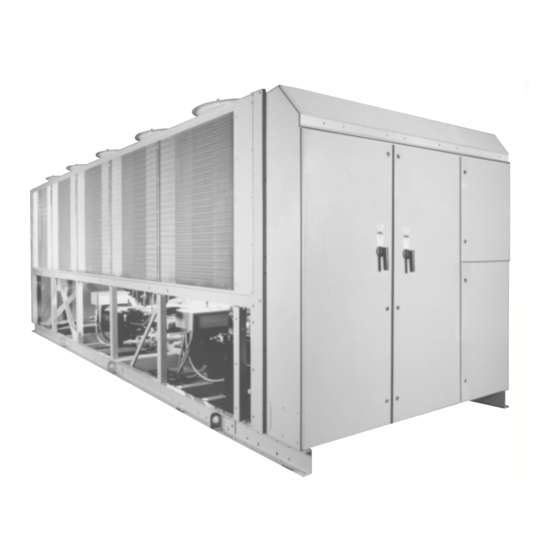
YCAS AIR-COOLED SCREW LIQUID CHILLER
YCAS 2-SYSTEM With EPROM
YCAS 3-SYSTEM EPROM
Microprocessor Board
YCAS 4-SYSTEM EPROM
Microprocessor Board
AIR-COOLED SCREW LIQUID CHILLERS
Supersedes: Nothing
MILLENNIUM
YCAS0373 – YCAS0653
031-01798-001
+
031-01798-002
031-02018-001
+
031-01798-002
031-02018-001
MILLENNIUM
TM
Form 201.18-NM2 (1199)
TM
(Standard, Brine & Metric Models Combined)
I/O Board EPROM
I/O Board EPROM
28971AR
Advertisement
Table of Contents

Subscribe to Our Youtube Channel
Related Manuals for York MILLENNIUM YCAS


Summary of Contents for York MILLENNIUM YCAS
- Page 1 MILLENNIUM AIR-COOLED SCREW LIQUID CHILLERS INSTALLATION, OPERATION, MAINTENANCE Supersedes: Nothing Form 201.18-NM2 (1199) MILLENNIUM YCAS AIR-COOLED SCREW LIQUID CHILLER YCAS0373 – YCAS0653 28971AR YCAS 2-SYSTEM With EPROM 031-01798-001 (Standard, Brine & Metric Models Combined) YCAS 3-SYSTEM EPROM 031-01798-002 031-02018-001 I/O Board EPROM Microprocessor Board YCAS 4-SYSTEM EPROM 031-01798-002...
-
Page 2: Table Of Contents
Power and Control Panel Layouts ....................... 35 SECTION COMMISSIONING Preparation ............................37 Preparation - Power Off ......................... 37 First Time Start-up ..........................39 SECTION OPERATION General Description ..........................40 Start-up ............................40 Normal Running and Cycling ....................... 40 Shutdown ............................40 YORK INTERNATIONAL... - Page 3 1.10 EMS/BAS Connections ......................102 1.11 Microprocessor Board Layout ....................104 1.12 Logic Section Layout ......................105 1.13 Anti-Recycle Timer ........................ 106 1.14 Anti-Coincidence Timer ......................106 1.15 Evaporator Pump Control ..................... 106 1.16 Compressor Heater Control ....................106 YORK INTERNATIONAL...
- Page 4 Program Key - User Programmable Values ............... 136 Programming "Default" Values .................... 139 Condenser Fan Control ......................141 SECTION MAINTENANCE General Requirements ........................142 Daily Maintenance .......................... 142 Scheduled Maintenance ........................ 142 Chiller/Compressor Operating Log ....................143 Maintenance Requirements ......................144 YORK INTERNATIONAL...
- Page 5 TABLE 2 - Condenser Fan Control and Fan Contactor Data for DXST Units with 4 Fans System ..141 TABLE 3 - Condenser Fan Control and Fan Contactor Data for DXST Units with 5 Fans System ..141 YORK INTERNATIONAL...
-
Page 6: General Safety Guidelines
NOT be installed inside the micro panel. NO external wiring is allowed to be run through the micro panel. All wiring must be in accordance with YORK’s published specifications and must be performed ONLY by qualified YORK personnel. YORK will not be responsible for damages/problems resulting from improper connections to the controls or application of improper control signals. -
Page 7: Changeability Of This Document
FORM 201.18-NM2 CHANGEABILITY OF THIS DOCUMENT In complying with YORK’s policy for continuous prod- It is the responsibility of operating/service personnel uct improvement, the information contained in this as to the applicability of these documents to the equip- document is subject to change without notice. While ment in question. -
Page 8: Section 1 General Chiller Information & Safety
Standards for Safety only be performed by suitably trained and qualified personnel. Millennium YCAS chillers are designed and built within an ISO 9002 accredited design and manufacturing or- The manufacturer will not be liable for any injury or ganization. The chillers comply with the applicable sec-... -
Page 9: Misuse Of Equipment
This manual, and any other document supplied with the age to the pressure system. No attempt should be made unit, are the property of YORK which reserves all rights. to gain access to the component parts of the pressure They may not be reproduced, in whole or in part, with-... -
Page 10: Emergency Shutdown
When operated, each removes The build-up of refrigerant vapor, from a leak for ex- the electrical supply from the control system, thus shut- ample, does pose a risk of asphyxiation in confined or ting down the unit. YORK INTERNATIONAL... -
Page 11: Material Safety Data
Fire Extinguishing Data Non-flammable. Containers Fire exposed containers should be kept cool with water sprays. Containers may burst if overheated. Fire Fighting Self-contained breathing apparatus and protective clothing must be worn in fire conditions. Protective Equip. YORK INTERNATIONAL... - Page 12 General Chiller Information & Safety MATERIAL SAFETY DATA Section 1 – PRODUCT NAME AND INFORMATION Product (Trade Name and Synonyms): YORK “L” Oil Chemical Name: Ester Chemical Family: Polyol Ester Formula: Proprietary CAS#: Proprietary Section 2 – COMPONENTS AND HAZARD STATEMENT This product is non-hazardous.
- Page 13 The information in this material safety data sheet should be provided to all who use, handle, store, transport, or are otherwise exposed to this product. CPI believes the information in this document to be reliable and up to date as of the date of publication, but makes no guarantee that it is. YORK INTERNATIONAL...
-
Page 14: Section 2 Product Description
3 mm (1/8") either side of a scribed line (equivalent to ASTM D1654 rating of “6”). YORK Millennium YCAS chillers are designed for All exposed power wiring is be routed through liquid- water or water-glycol cooling. All units are designed to tight, non-metallic conduit. -
Page 15: Fig. 2 - Screw Compressor
–29ºC (–20ºF) ambient and in- sulated with flexible closed-cell foam. The water nozzles are provided with grooves for me- chanical couplings and should be insulated by the con- tractor after pipe installation. LD03674 FIG. 2 – SCREW COMPRESSOR YORK INTERNATIONAL... - Page 16 The wet vapor to the economizer is supplied by a small The oil (YORK “L” oil - a POE oil used for all refriger- 15 ton TXV set for 5.5ºC (10ºF) superheat that flashes ant applications), which drains back into the compres- off 10- 20% of the liquid from the condenser.
- Page 17 The panel enclosures are de- mal storage, automatic pump down, run signal contacts, demand load limit from external building automation sys- signed to IP55 and are manufactured from powder painted galvanized steel. tem input, remote reset liquid temperature reset input, YORK INTERNATIONAL...
- Page 18 Since the micro is sending a run signal to the contactor, The 2ACE module design uses one integral current trans- it senses the low motor current below 10% FLA and former per phase to provide protection against rapid shuts the system down. YORK INTERNATIONAL...
- Page 19 (High Phase - Low Phase) / High Phase position requires pushing the switch to the left. Improper Phase Sequence It is recommended that a YORK Ser- vice Technician or the YORK factory The 2ACE module calculates the phase sequence at...
-
Page 20: Table 1 - Motor Protector Dip Switch Settings
Product Description TABLE 1 – MOTOR PROTECTOR DIP SWITCH SETTINGS DIP SWITCH SETTINGS ON MP (“1” INDICATES “ON”) CALCULATED TRIP SETTING YORK INTERNATIONAL... - Page 21 FORM 201.18-NM2 TABLE 1 – (CONT’D) MOTOR PROTECTOR DIP SWITCH SETTINGS DIP SWITCH SETTINGS ON MP (“1” INDICATES “ON”) CALCULATED TRIP SETTING YORK INTERNATIONAL...
- Page 22 Product Description TABLE 1 – (CONT’D) MOTOR PROTECTOR DIP SWITCH SETTINGS DIP SWITCH SETTINGS ON MP (“1” INDICATES “ON”) CALCULATED TRIP SETTING YORK INTERNATIONAL...
- Page 23 FORM 201.18-NM2 TABLE 1 – (CONT’D) MOTOR PROTECTOR DIP SWITCH SETTINGS DIP SWITCH SETTINGS ON MP (“1” INDICATES “ON”) CALCULATED TRIP SETTING YORK INTERNATIONAL...
-
Page 24: Motor Starting
1S (SYS 1) or 2S (SYS 2) contacts, energiz- Entry – Used to confirm Set Point changes, cancel in- ing motor contactor 2M (SYS 1) or 4M (SYS 2), com- puts, advance day, and change AM/PM. pleting the “DELTA” connection of the motor. YORK INTERNATIONAL... -
Page 25: Accessories And Options
Printed circuit board to accept 4 to 20 mA, 0 to 10 VDC, ACCESSORIES AND OPTIONS or dry contact closure input from the BAS. A YORK ISN Building Automation System can pro- Multiple Point Power Connection (Standard) vide a Pulse Width Modulated (PWM) signal direct to... -
Page 26: Dx Cooler Options
51 mm (2"). Level adjustable, deflec- heavy gauge welded wire mesh guards mounted around tion may vary slightly by application. (Field mounted). the bottom of the unit (Factory or field mounted). YORK INTERNATIONAL... -
Page 27: Unit Nomenclature Nameplate Engineering Data
14 15 BASE PRODUCT TYPE NOMINAL CAPACITY UNIT DESIGNATOR REFRIGERANT VOLTAGE/STARTER DESIGN/DEVELOPMENT LEVEL :Design Series F Tons :200 / 3/ 60 : YORK High Efficiency :R-22 :Engineering 0130 :230 / 3 /60 : Chiller Change 0140 :380 / 3/ 60... -
Page 28: Section 3 Handling And Storage
FIG. 4 – LIFTING LUGS Major damage must be reported immediately to your local YORK representative. The unit must only be lifted by the base frame at the points provided. Never move the unit on roll- ers, or lift the unit using a fork-lift truck. -
Page 29: Section 4 Installation
120 mm tion the same requirement of static pressure loss ap- (4-3/4") wide at the contact points. This will allow vibra- plies as for ducts and attenuators stated above. tion isolators to be fitted if required. YORK INTERNATIONAL... -
Page 30: Installation Of Vibration Isolators
1" N.P.T. connection can be obtained with each unit. from YORK as an accessory for the unit. Alternatively, a differential pressure switch sited across an orifice plate Using the Isolator tables (pages 76 - 82), refer to the may be used, preferably of the high/low limit type. -
Page 31: Water Treatment
Aerated, brackish or salt water is not recommended for low and high points in the pipework to permit drainage use in the water system(s). YORK recommends that a of the system and to vent any air in the pipes. water treatment specialist is consulted to determine that... -
Page 32: Connection Types & Sizes
It is recommended that a piece of pipe is fitted to each Where cross winds may occur, any ductwork must be valve and directed so that when the valve is activated the supported to prevent side loading on the unit. YORK INTERNATIONAL... -
Page 33: Electrical Connection
This will prevent recircu- tion (not supplied by YORK). lation of air when only one of the fans is running. Units are supplied with outlet guards for safety and to prevent damage to the fan blades. - Page 34 RS 232 port. the customer master start/stop so that the YORK con- tact can start the pump in the event of a low tempera- Remote Set Point Offset - Temperature ture liquid condition.
-
Page 35: Power And Control Panel Layouts
STAR / DELTA DOOR INTERLOCKED COMPRESSOR CONTACTORS CIRCUIT BREAKER RELAY BOARDS I/O EXPANSION BOARD CONTROL PANEL TRANSFORMERS POWER SUPPLY BOARD CIRCUIT BREAKERS 28965A MICROPROCESSOR CUSTOMER CIRCUIT BOARD CONNECTIONS (Flow Switch, Alarm, Run, 115VAC supply, etc.) FIG. 8 – PANEL LAYOUTS YORK INTERNATIONAL... -
Page 36: Fig. 9 - Customer Connections
Flow Switch System No. 1 Run System No. 1 Alarm Contacts System No. 2 Run Current Chilled Liquid Circulating Pump Start Temperature System No. 2 Print Alarm Contacts Chiller Run Isolator Auxiliary Interlock LD03502 FIG. 9 – CUSTOMER CONNECTIONS YORK INTERNATIONAL... -
Page 37: Section 5 Commissioning
Verify that the site voltage supply corresponds to the Compressor Oil unit requirement and is within the limits given in the Tech- To add oil to a circuit - connect a YORK hand oil pump nical Data Section. (Part No. 470-10654-000) to the 6 mm (1/4”) oil charg-... - Page 38 (offset) is to be used, the maximum reset must be pro- limits given in the Technical Data Section. Operation grammed by pressing the ‘Remote Reset Temp’ key. outside of these limits is undesirable and could cause (See Section 6.) damage. YORK INTERNATIONAL...
-
Page 39: First Time Start-Up
When all run cor- erant is in the system, the bubbles will disappear and be rectly, stop the unit, switch all applicable switches to the replaced by a solid column of liquid. ‘ON’ position and restart the unit. YORK INTERNATIONAL... -
Page 40: Section 6 Operation
The units are designed to work independently, or in con- automatic. After an initial period at minimum capacity junction with other equipment via a YORK ISN build- on the lead compressor, the control system will adjust ing management system or other automated control sys- the unit load depending on the chilled liquid temperature tem. -
Page 41: Temperatures And Flows
1. For leaving brine temperature below 4.4°C, contact your nearest YORK office for application requirements. 2. For leaving water temperature higher than 13°C, contact the nearest YORK office for application guidelines. 3. The evaporator is protected against freeze-up to -28.8°C with an electrical heater as standard. -
Page 42: Glycol Correction Factors
(see correction factors to be applied 1.25 when using glycol solutions). Special care must be taken 1.20 not to exceed the maximum allowed. 1.15 1.10 1.05 Correction Factor Mean Temperature through Cooler PROPYLENE GLYCOL Concentration W/W LD03504 FIG. 11 – GLYCOL CORRECTION FACTORS YORK INTERNATIONAL... -
Page 43: Physical Data
PRESSURE (Pa) HIGH PRESS. FANS OPTION 2 SLOW SPEED FANS ELECTRICAL THREE PHASE 50 Hz (V) * Maximum Ambient w/ High Ambient Kit is 52ºC. SOUND POWER DATA (PRELIMINARY) MODEL YCAS 0373EC 0403EC 0453EC 0503EC 0543EC 0573EC 0623EC 0653EC YORK INTERNATIONAL... -
Page 44: Refrigerant
Maximum Refrigerant Side Pressure, Bar Minimum Chilled Water Flow Rate, l/sec. 10.9 11.4 11.4 12.1 13.4 Maximum Chilled Water Flow Rate, l/sec. 37.9 37.9 37.9 37.9 47.1 47.1 47.1 47.1 Water Connections, inches Optional 21 Bar Waterside available YORK INTERNATIONAL... -
Page 45: R-407C Refrigerant
Maximum Refrigerant Side Pressure, Bar Minimum Chilled Water Flow Rate, l/sec. 10.9 11.4 11.4 12.1 13.4 Maximum Chilled Water Flow Rate, l/sec. 37.9 37.9 37.9 37.9 47.1 47.1 47.1 47.1 Water Connections, inches Optional 21 Bar Waterside available YORK INTERNATIONAL... -
Page 46: Electrical Data
(2) # 1 - 500 (3) 2/0-400 0543 (2) # 2 - 300 (2) 3/0-250 0573 (2) # 1 - 500 (3) 2/0-400 0623 (2) # 1 - 500 (3) 2/0-400 0653 (2) # 1 - 500 (3) 2/0-400 YORK INTERNATIONAL... - Page 47 17.1 107.9 17.1 0403 117.7 17.1 117.7 17.1 0453 139.5 17.1 139.5 17.1 0503 161.3 17.1 161.3 17.1 0543 140.6 17.1 140.6 17.1 0573 167.9 17.1 167.9 17.1 0623 183.1 17.1 183.1 17.1 0653 167.9 17.1 167.9 17.1 YORK INTERNATIONAL...
-
Page 48: Optional Single Point Power Supply Connection With Internal Unit Circuit Breakers
492 428 259 214 193 171 492 428 259 214 193 171 338 294 178 147 135 118 FAN DATA NOMINAL POWER FULL LOAD AMPS LOCKED ROTOR AMPS FAN TYPE (kW) (FLA) (LRA) STANDARD 1, 57 4, 4 18, 0 HIGH PRESSURE 3, 7 6, 8 46, 3 YORK INTERNATIONAL... -
Page 49: Electrical Notes & Legend
MINIMUM CIRCUIT AMPACITY MINIMUM MIN NF MINIMUM NON-FUSED RUNNING LOAD AMPS S.P. WIRE SINGLE-POINT WIRING UNIT MTD SERV SW UNIT-MOUNTED SERVICE (NON-FUSED DISCONNECT SWITCH) WYE-DELTA WYE-DELTA START XLRA ACROSS-THE-LINE INRUSH LOCKED ROTOR AMPS YLRA WYE-DELTA INRUSH LOCKED ROTOR AMPS YORK INTERNATIONAL... -
Page 50: Power Connection Options
Y-D D D D D Start and Across-The-Line Start SEE NOTE 2 LD04106 OPTIONAL SINGLE-POINT POWER SUPPLY WITH INTERNAL UNIT CIRCUIT BREAKERS Optional Field Provided 115-1Ø MicroPanel Supply Suitable for: Y-D D D D D Start and Across-The-Line Start SEE NOTE 2 LD04107(50) YORK INTERNATIONAL... -
Page 51: Optional Single Point Power Supply Connection To Factory Circuit Breaker
1. – – – – – – – Dashed Line indicates Field Provided Wiring. 2. The above recommendations are based on the National Electrical Code and using copper conductors only. Field wiring must also comply with local codes. YORK INTERNATIONAL... -
Page 52: Wiring Diagrams
Transient Voltage Suppression Terminal Block for Customer Connections Terminal Block for Customer Low Voltage (Class 2) Connections. See Note 2 Terminal Block for YORK Connections Only Wiring and Components by YORK Optional Equipment Wiring and/or Components by Others FIG. 12 – ELEMENTARY DIAGRAM – ACROSS-THE-LINE START... - Page 53 FORM 201.18-NM2 WIRING DIAGRAM ACROSS-THE-LINE START YORK INTERNATIONAL...
- Page 54 Technical Data ELEMENTARY DIAGRAM FIG. 12 – CONTINUED YORK INTERNATIONAL...
- Page 55 Any contacts connected to flow switch inputs or BAS inputs on terminals 13 - 19 or TB3, or any other terminals, must be sup- pressed with a YORK P/N 031- 00808-000 suppressor across the relay/contactor coil. CAUTION: Control wiring connected to...
-
Page 56: Across-The-Line Start
Technical Data FIG. 13 – POWER PANEL (FRONT INSIDE VIEW) – ACROSS-THE-LINE START YORK INTERNATIONAL... -
Page 57: Across-The Line Start
FORM 201.18-NM2 LD03280 FIG. 14 – ELECTRONIC PANEL (FRONT INSIDE VIEW) – ACROSS-THE-LINE START YORK INTERNATIONAL... -
Page 58: Fig. 15 - Elementary Diagram: Wye-Delta Start
Transient Voltage Suppression Terminal Block for Customer Connections Terminal Block for Customer Low Voltage (Class 2) Connections. See Note 2 Terminal Block for YORK Connections Only Wiring and Components by YORK Optional Equipment Wiring and/or Components by Others FIG. 15 – ELEMENTARY DIAGRAM – WYE-DELTA START... - Page 59 FORM 201.18-NM2 WIRING DIAGRAM WYE-DELTA START FIG. 15 – CONT’D LD03229 YORK INTERNATIONAL...
- Page 60 Technical Data ELEMENTARY DIAGRAM FIG. 15 – CONTINUED YORK INTERNATIONAL...
- Page 61 Any contacts connected to flow switch inputs or BAS inputs on terminals 13 - 19 or TB3, or any other terminals, must be sup- pressed with a YORK P/N 031- 00808-000 suppressor across the relay/contactor coil. CAUTION: Control wiring connected to the...
-
Page 62: Fig. 16 - Power Panel (Front Inside View) Wye-Delta Start
Technical Data FIG. 16 – POWER PANEL (FRONT INSIDE VIEW) - WYE-DELTA START YORK INTERNATIONAL... -
Page 63: Fig. 17 - Electronic Panel (Front Inside View)
FORM 201.18-NM2 LD03280 FIG. 17 – ELECTRONIC PANEL (FRONT INSIDE VIEW) – WYE-DELTA START YORK INTERNATIONAL... -
Page 64: Fig. 18 - Connection Diagram
Technical Data LEGEND – FIGS. 12 THROUGH 16 CONNECTION DIAGRAM ELECTRIC BOX DXST DIRECT DRIVE FIG. 18 – CONNECTION DIAGRAM LD03281 YORK INTERNATIONAL... -
Page 65: Fig. 19 - Detail "A
FORM 201.18-NM2 LD03282 LD03283 LD03284 FIG. 19 – DETAIL “A” (see pages 54 - 59) YORK INTERNATIONAL... -
Page 66: Fig. 20 - Connection Diagram System Wiring
Technical Data CONNECTION DIAGRAM (SYSTEM WIRING) LD03230 FIG. 20 – CONNECTION DIAGRAM SYSTEM WIRING FIG. 21 – SENSOR CONNECTION LD03231 LD03232 FIG. 22 – COMPRESSORS (SYSTEMS 1 & 2) YORK INTERNATIONAL... -
Page 67: Fig. 23 - Compressor Terminal Boxes
FORM 201.18-NM2 COMPRESSOR TERMINAL BOX LD03233 FIG. 23 – COMPRESSOR TERMINAL BOXES YORK INTERNATIONAL... -
Page 68: Fig. 24 - Detail "B
Technical Data FIG. 24 – DETAIL “B” YORK INTERNATIONAL... -
Page 69: Fig. 25 - Detail "C
FORM 201.18-NM2 #3/#4 #3/#4 #5/#6 #5/#6 #7/#8 #3/#4 #3/#4 #5/#6 #5/#6 #7/#8 #7/#8 #9/#10 #9/#10 #11/#12 FIG 25 – DETAIL “C” YORK INTERNATIONAL... -
Page 70: Dimensions
Site restrictions may compromise minimum clearances indicated below, resulting in unpre- dictable air flow patterns and possible diminished performance. YORK's unit controls will optimize operation without nuisance high pressure safety cutout; however, the system designer must consider potential performance degradation. Access to the unit control center assumes the unit is no higher than on spring isolators. - Page 71 CENTER OF GRAVITY (Copper) YCAS YCAS 0373 2324.1 1130.3 889.0 0373 2331.7 1127.8 960.1 0403 2324.1 1130.3 889.0 0403 2331.7 1127.8 960.1 0453 2324.1 1137.9 886.5 0453 2331.7 1135.4 955.0 0503 2324.1 1137.9 886.5 0503 2331.7 1135.4 955.0 LD02985 YORK INTERNATIONAL...
-
Page 72: Ycas0543 - Ycas0623
Site restrictions may compromise minimum clearances indicated below, resulting in unpre- dictable air flow patterns and possible diminished performance. YORK's unit controls will optimize operation without nuisance high pressure safety cutout; however, the system designer must consider potential performance degradation. Access to the unit control center assumes the unit is no higher than on spring isolators. - Page 73 FORM 201.18-NM2 LD02994 CENTER OF GRAVITY (Alum.) CENTER OF GRAVITY (Copper) YCAS YCAS 0543 2717.8 1087.1 914.4 0543 2755.9 1092.2 988.1 0573 2717.8 1097.3 914.4 0573 2753.4 1097.3 988.1 0623 2717.8 1097.3 914.4 0623 2753.4 1097.3 988.1 2718 LD02995 YORK INTERNATIONAL...
- Page 74 Site restrictions may compromise minimum clearances indicated below, resulting in unpre- dictable air flow patterns and possible diminished performance. YORK's unit controls will optimize operation without nuisance high pressure safety cutout; however, the system designer must consider potential performance degradation. Access to the unit control center assumes the unit is no higher than on spring isolators.
- Page 75 FORM 201.18-NM2 LD03004 CENTER OF GRAVITY (Alum.) CENTER OF GRAVITY (Copper) YCAS YCAS 0653 3032.8 1097.3 965.2 0653 3106.4 1099.8 1041.4 LD03005 YORK INTERNATIONAL...
-
Page 76: Ycas0653
25.9 Green AWMR-1-532 1500 680.4 CP-2-31 2200 997.9 0.83 21.0 Gray AWMR-1-551 1676 760.2 CP-2-32 2600 1179.3 0.74 18.7 White AWMR-1-552 1900 861.8 CP-2-35 3000 1360.8 0.70 17.7 Gold AWMR-1-553 2200 997.9 AWMR-2-531 2552 1157.6 AWMR-2-532 3000 1360.8 YORK INTERNATIONAL... -
Page 77: Isolator Selection - Aluminum Fin Coils
–– –– –– 0573 -1-552 -1-551 -1-552 -1-532 -1-553 -1-532 -1-552 -1-551 –– –– –– –– –– –– –– –– 0623 -1-553 -1-552 -2-531 -1-531 -1-553 -1-551 -2-531 -1-531 –– –– –– –– –– –– –– –– 0653 YORK INTERNATIONAL... -
Page 78: Operating Weights - Copper Fin Coils
1/4" shim be- ance of 1/8" between resilient washer and under- tween the upper load plate and vertical uprights. side of channel cap plate. Lower the equipment on the blocking or shimmed 10. Installation is now complete. isolators. YORK INTERNATIONAL... -
Page 79: Isolator Selection - Copper Fin Coils
–– –– –– 0573 -1-552 -1-551 -1-552 -1-532 -1-553 -1-532 -1-552 -1-551 –– –– –– –– –– –– –– –– 0623 -1-553 -1-552 -2-531 -1-531 -1-553 -1-551 -2-531 -1-531 –– –– –– –– –– –– –– –– 0653 YORK INTERNATIONAL... -
Page 80: Fig. 26 - Isolator Details
63.5 12.7 104.8 14.4 R-3 or RD-3 (5.5") (3.375") (2.875") (2.5") (0.5") (4.125") (0.563") (0.25") 158.7 117.6 69.8 76.2 12.7 127.0 14.4 R-4 or RD-4 (6.25") (4.625") (2.75") (3.0") (0.5") (5.0") (0.563") (0.375") FIG. 26 – ISOLATOR DETAILS YORK INTERNATIONAL... -
Page 81: Fig. 27 - Isolator Details
AWMR-4 1-1/4 7-1/2 3-3/4 7-3/4 14-1/2 7-1/4 1000-1628 AWMR-1 10-1/2 3-1/2 1-3/4 8-1/2 4-1/4 10-1/2 50-553 11NC AWMR-2 7-1/2 3-3/4 9-1/2 14-1/2 7-1/4 50-553 10NC AWMR-4 1-1/4 7-1/2 3-3/4 9-3/4 14-1/2 7-1/4 52-553 FIG. 27 – ISOLATOR DETAILS YORK INTERNATIONAL... -
Page 82: Fig. 28 - Isolator Locations
Technical Data ISOLATOR LOCATIONS MODELS YCAS 0373 0403 0453 0503 LD03081 MODELS YCAS 0543 0573 0623 0653 LD03019 FIG. 28 – ISOLATOR LOCATIONS YORK INTERNATIONAL... -
Page 83: Fig. 29 - Clearances
FORM 201.18-NM2 CLEARANCES 1.3 m (48") (72") LD03484 Notes: No obstructions allowed above the unit. Only one adjacent wall may be higher than the unit. Adjacent units should be 3 meters (10 feet) apart. FIG. 29 – CLEARANCES YORK INTERNATIONAL... -
Page 84: Refrigerant Flow Diagram
The high pressure oil-free vapor is fed to the Air- place before returning to the cooler. cooled condenser coil and fans where the heat is removed. The fully condensed liquid enters the economizer. FIG. 30 – REFRIGERANT FLOW DIAGRAM YORK INTERNATIONAL... -
Page 85: Process And Instrumentation Diagram
FORM 201.18-NM2 PROCESS AND INSTRUMENTATION DIAGRAM FIG. 31 – PROCESS AND INSTRUMENTATION DIAGRAM LD03486 YORK INTERNATIONAL... -
Page 86: Component Locations
HIGH PRESSURE CUT-OUT - STS SUCTION TEMPERATURE SENSOR - RFTS REFRIGERANT FEED TEMPERATURE SENSOR (R407C only) - XCMTB COMPRESSOR MOTOR TERMINAL BOX - YELSSV ECONOMIZER LIQUID SUPPLY SOLENOID VALVE - ZCPR COMPRESSOR LD03487 FIG. 32 – COMPONENT LOCATIONS YORK INTERNATIONAL... -
Page 87: Compressor Components
STATOR LOCKING BOLT OIL FILTER COVER PLATE OIL FILTER BLEED & EVACUATION POINT LIFTING LUG THREADED HOLE HEATER ECONOMIZER GAS IN DISCHARGE CASE DISCHARGE GAS OUT OIL INLET FROM CONDENSER CODING COIL LD03668 FIG. 33 – COMPRESSOR COMPONENTS YORK INTERNATIONAL... -
Page 88: Fig. 12 - Elementary Diagram: Fig. 34 - Component Locations
Technical Data COMPRESSOR COMPONENTS - CONT’D LD03669 FIG. 34 – COMPRESSOR COMPONENTS YORK INTERNATIONAL... -
Page 89: Fig. 35 - Component Locations
FORM 201.18-NM2 COMPRESSOR COMPONENTS - CONT’D LD03670 FIG. 35 – COMPRESSOR COMPONENTS YORK INTERNATIONAL... -
Page 90: Fig. 13 - Power Panel (Front Inside View) Fig. 36 - Component Locations
Technical Data COMPRESSOR COMPONENTS - CONT’D LD03671 FIG. 36 – COMPRESSOR COMPONENTS YORK INTERNATIONAL... -
Page 91: Fig. 37 - Component Locations
FORM 201.18-NM2 COMPRESSOR COMPONENTS - CONT’D SLIDE VALVE RETURN SPRING MOTOR ROTOR / MALE ROTOR LOCKING KEY O-RING MALE ROTOR RELIEF O-RING SLIDE VALVE VALVE SUPPORT RINGS ECONOMIZER PLUG FEMALE ROTOR FIG. 37 – COMPRESSOR COMPONENTS LD03672 YORK INTERNATIONAL... -
Page 92: Fig. 14 - Electronic Panel (Front Inside View) Fig. 38 - Component Locations
BEARING CLAMP NUT REVERSE THRUST BEARING THRUST SPACER SHIM THRUST BEARINGS SPACER SHIM DISCHARGE RADIAL BEARING LIP SEAL DOWEL PIN SUPPORT RING ECONOMIZER PLUG SUPPORT RING FEMALE ROTOR RETAINING RING FEMALE INLET BEARING FIG. 38 – COMPRESSOR COMPONENTS YORK INTERNATIONAL... -
Page 93: Section 8 Start-Up
START-UP If it is necessary to add oil, connect a YORK oil TECHNICIAN/ pump to the charging valve on the oil separator, COMPANY: _______________________________... - Page 94 4. Check the system operating parameters. Do this Dischg Press Cut-out = ____________ kPa (PSIG) by selecting various displays such as pressures Disch Press Unld = _______________ kPa (PSIG) and temperatures. Compare these to test gauge readings. Suction Press Cut-out = ____________ kPa (PSIG) YORK INTERNATIONAL...
- Page 95 ____ ____ ____ (KPA)(PSIG) Superheat = ____ ____ ____ ____ °C (0°F) Temp = ____ ____ ____ ____ °C (°F) Liq Line Temp = ____ ____ ____ ____ °C (°F) Subcooling = ____ ____ ____ ____ °C (°F) YORK INTERNATIONAL...
- Page 96 (approximately 15 minutes) between adjust- ments for the system and the thermal expansion valve to respond and settle out. Assure that superheat is set between 6-7°C (10 -12°F). YORK INTERNATIONAL...
-
Page 97: Section 9 Micropanel Chiller Control Panel Programming & Data Access
This switch shuts down the entire chiller when placed in This key is used for display and programming of the the OFF position. The switch must be ON for the chiller chiller operational settings and limits. to operate. YORK INTERNATIONAL... -
Page 98: Introduction & Physical Description
External interface is available for control of the chiller to turn the entire chiller OFF, if desired. The switch via a YORK ISN System or YORK Remote Control must be placed in the ON position for the chiller to op- Center. -
Page 99: Ancillary Circuit Boards
One Relay Output Board per system operates the mo- While a chiller is operating, the clock must be ON (Sec- tor contactors / starters, solenoid valves, and heaters tion 1.11, Item 1) or the internal clock on the micropro- which control system operation. YORK INTERNATIONAL... -
Page 100: Circuit Breakers
Power Supply Board which rectifies and filters the signals to variable DC Voltage (analog). These The module also provides phase rotation protection to analog levels are then fed to the Microprocessor Board assure the screw compressor does not rotate backwards. YORK INTERNATIONAL... -
Page 101: Fig. 39 - Motor Protector
FORM 201.18-NM2 29119A SIDE VIEW 29121A 29121A TOP VIEW TOP VIEW DISPLAY SWITCH PUSHED TO LEFT INDICATES “ON” 29120A SIDE VIEW FIG. 39 – MOTOR PROTECTOR YORK INTERNATIONAL... -
Page 102: Ems/Bas Connections
Remote Reset Curr = 105% FLA - {(4sec - 1 sec) X (75%FLA)} shown in Section 1.12. 10 sec Never bypass a flow switch. This will = 105% - 225%FLA sec 10 sec cause damage to the chiller and void any warranties. = 82.5% FLA YORK INTERNATIONAL... - Page 103 If an inductive device Reset Temp = 66°C sec (relay, contactor) is supplying these 10 sec contacts, the coil of the device must = 6ºC (12ºF) be suppressed with a standard RC sup- pressor (50Hz models) across the in- ductive coil. YORK INTERNATIONAL...
-
Page 104: Microprocessor Board Layout
NOTE : Dimple is positioned at top edge Dip Switch Set (8 switches) S2 to S5 System Switches S2 = System 1 S3 = System 2 S4 = System 3 S5 = System 4 FIG. 40 – COMPONENT LAYOUT YORK INTERNATIONAL... -
Page 105: Logic Section Layout
50HZ MODEL LOGIC SECTION ITEM DESCRIPTION Microprocessor Board Back of Keypad Back of Display I/O Expansion Board Power Supply Board Relay Output Board #1 Relay Output Board #2 Flow Switch & Customer Connection Terminals FIG. 41 – LOGIC SECTION LAYOUT YORK INTERNATIONAL... -
Page 106: Anti-Recycle Timer
(150 ºF) and will turn on when the discharge temperature tem or if power is lost to the control panel. The internal is equal to or less than 66°C (150 ºF). contacts are normally open (N.O.) and will close when YORK INTERNATIONAL... -
Page 107: Run Status (Chiller)
ON or OFF. cal equipment) and the alarm circuit should fail to function, YORK will not MANUAL Lead/Lag selection will be automatically be liable for damages. overridden by the micro to allow the lag compressor to automatically become the lead anytime the selected lead 1.20 RUN STATUS (CHILLER) -
Page 108: Status Key & Fault Messages
This message indicates that either an ISN or RCC (Re- amples of each display. In each example "#" is used as mote Control Center) has turned the unit OFF through applicable to represent the system number where mes- the RS-485 port. sages apply to individual systems. YORK INTERNATIONAL... -
Page 109: Unit Warnings
Section 7.4. This allows reprogram- out. The display shows the time before the respective ming of setpoints, cutouts, and compressor can start. This display will only appear af- ter the anti-recycle timers have timed out. schedule. YORK INTERNATIONAL... -
Page 110: Anticipation Control Status Messages
S U C T L I M I T I N G the Unit Switch must be cycled OFF and ON to start S Y S S U C T L I M I T I N G the unit. YORK INTERNATIONAL... -
Page 111: Unit Fault Status Messages
Section 8.2 / Leaving Water Temperature Cutout, page 138). The chiller fault will clear when temperature Any time that a Unit Fault occurs, the shutdown will be rises 2°C (4ºF) above the cut-out and cooling demand logged into the HISTORY BUFFER. exists. YORK INTERNATIONAL... -
Page 112: System Fault (Safety) Status Messages
3 For the first 4 seconds of operation discharge tempera- seconds. Automatic restart will occur after the first 2 shutdowns when the anti-recycle timer times out and ture is ignored. After 4 seconds of operation the com- YORK INTERNATIONAL... - Page 113 3.4 bar (50 PSID) or the tion pressure falls below the calculated cutout value system will be shut down. For lower ambients, the lin- before 225 seconds of run time, the system will be shut ear ramp times are as follows: down. YORK INTERNATIONAL...
-
Page 114: Fig. 42 - Suction Pressure Cutout
From this time the system will programmable between 0.3 - 5 bar (5 - 70 PSIG) for R- be shut down if average motor current is less than 10% 22 and R407c models. In this mode, the cutout should of FLA. YORK INTERNATIONAL... -
Page 115: Printout On Fault Shutdown
This is not a cause for A/L Start: Dial Setting = (1.1 x RLA) / 350 concern. WYE-Delta Start: Dial Setting = (0.64 x RLA) / 350 YORK INTERNATIONAL... -
Page 116: Display Keys & Option Switches
The Display keys and the data available from each is as ture, discharge superheat and compressor slide valve follows: position. 3.2 CHILLED LIQUID TEMPS KEY Examples of these displays are as follows where # is When the Chilled Liquid Temperatures key is pressed, the appropriate system number : YORK INTERNATIONAL... -
Page 117: Ambient Temp Key
This display shows the average motor current in amps 0 -40. and average compressor motor current as a percentage of FLA. All values are approximate. Keep in mind that Superheats are the difference between the respective current in “amps” is an “approximate” value. YORK INTERNATIONAL... -
Page 118: Operating Hours / Start Counter Key
At the end of the sequence, above -4°C (25ºF) can be used to automatically shut the display will automatically revert to the first Option down the chiller when direct cooling methods become Switch message. operational. YORK INTERNATIONAL... -
Page 119: Function Key
After scrolling through the data, the display returns to the status message. The following keys can be scrolled using the Function Key: Chilled Liquid Temps, System # Data, Motor Current and Options. YORK INTERNATIONAL... -
Page 120: Print Keys
“rate control” ted from the microprocessor to the remote printer. As and “temperature deviation from setpoint” to determine the data is transmitted it is erased from the memory. when loading should occur. YORK INTERNATIONAL... - Page 121 PWM TEMP – EMS PWM Temp. Reset Enabled tem. Both systems have their own control panel, but only the System 1 and 2 panel is fitted with a keypad CUR/TEMP – EMS PWM Current Limiting & Temperature Reset Enabled and display. YORK INTERNATIONAL...
-
Page 122: Operating Data - Remote Printout
SUCTION SUPERHEAT 11.2 ºF for the appropriate number of systems: SAT DISCHARGE TEMP 112.1 ºF DISCHARGE SUPERHEAT 33.4 ºF YORK INTERNATIONAL CORPORATION SLIDE VALVE STEP MILLENNIUM SCREW CHILLER COOLER INLET REFRIG 23.6 ºF LIQUID LINE SOLENOID ECONOMIZER TXV SOLENOID UNIT STATUS... -
Page 123: History Key
This message displays the suction pressure cut-out pro- grammed at the time of the fault. S H U T D O W N O C C U R R E D 5 : 5 9 A M N O V YORK INTERNATIONAL... - Page 124 A mixed water sensor may be system was ON or OFF at the time of the fault. present when multi-unit sequencing is utilized. If no mixed water temperature sensor is installed, the display will not appear. YORK INTERNATIONAL...
- Page 125 One section contains numbers 1 and 2 refrigerant 407C mode, indicates the refrigerant temperature at the systems and the associated evaporator. The second sec- inlet of the cooler. tion contains number 3 and 4 refrigerant systems and YORK INTERNATIONAL...
-
Page 126: Fault History Data - Remote Printout
218 PSIG SUCTION TEMPERATURE 42.9 ºF DISCHARGE TEMPERATURE145.5 ºF OIL TEMPERATURE 102.8 ºF SAT SUCTION TEMP 31.7 ºF YORK INTERNATIONAL CORPORATION SUCTION SUPERHEAT 11.2 ºF MILLENNIUM SCREW CHILLER SAT DISCHARGE TEMP 112.1 ºF DISCHARGE SUPERHEAT 33.4 ºF SAFETY SHUTDOWN NUMBER 1... -
Page 127: Entry Keys
“AM” or “PM” on the display. For â â â â â this is not done, the new values entered will be lost and example, pressing the key when the cursor is on “PM” the original values will be returned. changes it to “AM”. YORK INTERNATIONAL... -
Page 128: Setpoints Keys
7ºC Temp. RANGE operating 6.2 CHILLED LIQUID TEMPERATURE CONTROL (44.0ºF) range) The Setpoints keys are used to program the required chilled water liquid temperature for the application. This 6ºC (42.0ºF) is accomplished by programming the "Setpoint" and the YORK INTERNATIONAL... - Page 129 At this point the compressors will be alternately loaded with loading Zero Unload Hold Load always occuring on the compressor with the lowest slide Positive Hold Load Load valve step until the leaving chilled liquid is satisfied. YORK INTERNATIONAL...
- Page 130 10 steps between system 1 and 2. It could only below the low limit of the Control Range. YORK INTERNATIONAL...
-
Page 131: Local Cooling Setpoints Key
After the Setpoint and Range is keyed in, press the application, remembering to use a leading "0" for values ENTER Key to store the data in memory. less than 10ºC (or 10ºF). Press the ENTER Key to store the new value in memory. YORK INTERNATIONAL... -
Page 132: Clock Keys
AM/PM designation. If stop schedule, as shown below, can be displayed using á á á á á â â â â â necessary press the key to change to the oppo- the Set Schedule / Holiday key: site time period. YORK INTERNATIONAL... - Page 133 Cancel. This will clear the programmed ULE will not affect on the holiday (*) “Holiday” days (the “0” key will not cancel out a “ * ” schedule. and cannot be used for correcting a programming error). YORK INTERNATIONAL...
-
Page 134: Manual Override Key
If a power failure should again occur, the above process will again need to M A N U A L be repeated to bring the chiller back O V E R R I D E on line. See also Section 2.5. YORK INTERNATIONAL... -
Page 135: Program Key
Failure to prop- desired language. erly program these values may cause damage to the Chiller or operating Pressing the Enter key repeatedly allows scrolling problems. through the programmable displays. YORK INTERNATIONAL... -
Page 136: Program Key - User Programmable Values
Typically the unload point should be set 1.4 to 1.7 bar (20 - 25 PSIG) below the below the discharge pressure 100 – 60 New Cutout = 3 = 1.2 bar (17.6PSIG) cutout setting. The micro will accept a range of pro- YORK INTERNATIONAL... - Page 137 -17ºC (1ºF) for more than programmable value is password protected. a short time. To program the High Ambient Cutout, key in the re- quired setting and press the Enter key to store the value into memory and scroll to the next display. YORK INTERNATIONAL...
- Page 138 If the programmable limit is set between 100% and 105% reduce cycling and maximize motor life. 600 seconds of full load current, this safety will protect against ex- is recommended. YORK INTERNATIONAL...
-
Page 139: Programming "Default" Values
This will preset all programmable values the system. Details of manual and automatic lead / lag under the Program key to values that will allow opera- operation are outlined in Section 1.21. YORK INTERNATIONAL... - Page 140 Low Amb. -4ºC 25°F High Ambient Temperature Cut-Out 38ºC 130°F Discharge Pressure Unload 26 bar 375PSIG High Motor Current Unload 100% Anti-Recycle Timer 600 sec. Leaving Chilled Liquid Temp Cut-Out 2ºC 36°F Suction Pressure Cut-Out 3 bar 44PSIG YORK INTERNATIONAL...
-
Page 141: Condenser Fan Control
<15.2 BAR & <29.4ºC 15M, 16M, 17M, 18M, 19M 230, 231, 232 10, 14, 15 TABLE 3 – CONDENSER FAN CONTROL & FAN CONTACTOR DATA FOR DXST UNITS WITH 5 FANS/SYSTEM FIGURE 44 – CONDENSER FAN LAYOUT FOR DXST 2-COMPRESSOR UNITS YORK INTERNATIONAL... -
Page 142: Section 10 Maintenance
Compressor Oil Level improper maintenance during the warranty period, Check the compressor oil level after the compressor YORK shall not be liable for costs incurred to return has been operating on ‘FULL LOAD’ for approximately the unit to satisfactory condition. -
Page 143: Chiller/Compressor Operating Log
YORK Order No. ________________________ CHILLER/COMPRESSOR Compr. Ser. No. _________________________ Operating Log Unit Ser. No. ___________________________ Refrigerant _____________________________ Date Time Hour Meter Reading Equipment Room Temp./Outdoor Temp. Suction Pressure Suction Temperature Suction Superheat Discharge Pressure Actual Discharge Temperature Oil Pressure Oil Temperature... -
Page 144: Maintenance Requirements
* Reserved for customer use for any special site determined requirements. This procedure must be performed at the specified time interval by an Industry Certified Technician who has been trained and qualified to work on this type of YORK equipment. A record of this procedure being successfully carried out must be maintained on file by the equipment owner should proof of adequate maintenance be... -
Page 145: General Periodic Maintenance Checks Standard Units
Check contactor contacts. Microprocessor controls: Check fault history. Check fan control function. Check program settings . Check ambient cut-out function. Check HP / LP cut-out function’s Check low oil pressure function. Check pump-down function. Check load / unload function. YORK INTERNATIONAL... -
Page 146: Spare Parts
Full unit model number, serial number, application and details of the parts required. All requests for parts should be made to your local YORK Sales and Service Center. RECOMMENDED COMPRESSOR OILS The correct type of oil must be used in the unit as shown on the unit data plate and labels. -
Page 147: Troubleshooting
Check that the compressor unloads correctly. Measured temperature is incorrect. Check sensor calibration, location and wiring. Chiller FAULT: VAC Check mains supply is stable and within allowable UNDERVOLTAGE Poor mains supply voltage. limits. displayed. Check for voltage dip on compressor start. YORK INTERNATIONAL... - Page 148 Check operation of economizer and motor cooling TEV’s and liquid solenoid valve. SYS # CURR LIMITING High compressor motor current has Check if liquid temperature is within operating limits. displayed activated unloading. Check if ambient air temperature is above operating (Compressor current limits. unloading.) YORK INTERNATIONAL...
-
Page 149: Sensor Calibration Charts
Test Point ............Micro-board J11-9/3 System 1: ............Micro-board J13-7/1 System 2: ............Micro-board J14-7/1 Oil Pressure: System 1: ............Micro-board J13-8/3 System 2: ............Micro-board J14-8/3 Discharge Pressure: System 1: ............Micro-board J15-8/3 System 2: ............Micro-board J15-7/1 YORK INTERNATIONAL... -
Page 150: Limited Warranty
BUYER’S SOLE AND EXCLUSIVE REMEDY IN Except for reciprocating replacement compressors, which THE EVENT OF A DEFECT IN WORKMANSHIP YORK warrants for a period of one year from date of OR MATERIALS. IN NO EVENT SHALL YORK’S shipment, YORK warrants reconditioned or replacement... -
Page 151: Temperature Conversion Chart
186.8 22.07 16.5 239.3 100.0 190.4 22.76 246.5 102.2 23.45 17.5 253.8 104.4 197.6 24.14 106.7 201.2 24.83 18.5 268.3 108.9 204.8 25.52 275.5 111.1 208.4 26.21 19.5 282.8 113.3 26.9 115.6 215.6 27.59 20.5 297.3 117.8 219.2 YORK INTERNATIONAL... - Page 152 Proud Sponsor of the 2000 U.S. Olympic Team 36USC380 P.O. Box 1592, York, Pennsylvania USA 17405-1592 Subject to change without notice. Printed in USA Copyright © by York International Corporation 1999 ALL RIGHTS RESERVED Form 201.18-NM2 (1199) Supersedes: None...
Need help?
Do you have a question about the MILLENNIUM YCAS and is the answer not in the manual?
Questions and answers