Table of Contents
Advertisement
Quick Links
Application Methods
Parking Lot Layout for LineLazer
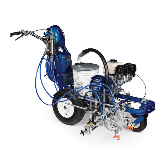
HP Auto Series with LazerGuide
For the application of line striping materials. For professional use only. For outdoor use
only. Not for use in explosive atmospheres or hazardous locations.
Maximum Operating Pressure: 3300 psi (22.8 MPa, 228 bar)
Important Safety Instructions
Read all warnings and instructions in this manual and in related manuals.
Be familiar with the controls and the proper usage of the equipment.
Save these instructions.
V
™
3A8102A
2000
™
EN
Advertisement
Table of Contents

Related Manuals for Graco LineLazer V HP Auto Series


Summary of Contents for Graco LineLazer V HP Auto Series
- Page 1 Application Methods Parking Lot Layout for LineLazer ™ 3A8102A HP Auto Series with LazerGuide 2000 ™ For the application of line striping materials. For professional use only. For outdoor use only. Not for use in explosive atmospheres or hazardous locations. Maximum Operating Pressure: 3300 psi (22.8 MPa, 228 bar) Important Safety Instructions Read all warnings and instructions in this manual and in related manuals.
-
Page 2: Table Of Contents
Graco Standard Warranty ........ -
Page 3: Linelazer V Auto-Layout System
LineLazer V Auto-Layout System GUN SETUP For parking lot layout applications, it is recommended that GUN 1 is placed on the right side of the striper and GUN 2 is placed on the left side. It is also important that the guns are placed straight across from one another slightly in front of the front tire. -
Page 4: Calibration
Calibration Minimum 24 ft precision course CALIBRATION 1. Lay out a steel measuring tape (minimum 25 ft, maximum 100 ft). 2. Line up the striper parallel to the tape measure with the LazerGuide 1700 Start/Stop Laser at the 1 ft mark. 3. -
Page 5: Measure Mode
Measure Mode Used for measuring and marking specific distances MEASURE MODE 1. Go to the MEASURE MODE screen on the LiveLook display. 2. Put the LazerGuide 1700 Start/Stop Laser on your START point and press the GUN TRIGGER CONTROL button. 3. -
Page 6: Basic Stall Layout: Layout Mode
Basic Stall Layout: Layout Mode Establishing START and FINISH reference dots NOTE: For best results, always dot in the same direction. NOTE: Minimum engine RPM for placing dots is 2600. LAYOUT MODE 1. Go to LAYOUT MODE on LiveLook display and select the depth of your stall as the STALL SIZE. In this case, we are selecting 18 ft from the inside curb. -
Page 7: Basic Stall Layout: Stall Calculator
Basic Stall Layout: Stall Calculator Measure for automatic calculation or select desired stall size STALL CALCULATOR 1. Move the striper to the START point. Line up the LazerGuide 1700 Start/Stop Laser with the START reference dot and align the LazerGuide 2000 Laser with the Target Box. NOTE: Make sure that you calibrate your LazerGuide 2000 as shown in manual 3A5294 or the 'LazerGuide 2000 Setup &... -
Page 8: Basic Stall Layout: Layout Mode
Basic Stall Layout: Layout Mode Mark dots at beginning of each stall LAYOUT MODE 1. Move the striper back to the START point. Line up the LazerGuide 1700 Start/Stop Laser with the START reference dot and align the LazerGuide 2000 Laser with the Target Box. 2. -
Page 9: Basic Stall Layout: Stall Calculator
Basic Stall Layout: Stall Calculator Mark dots near the curb LAYOUT MODE 1. Move the striper such that the LazerGuide 1700 Start/Stop Laser is at the curb to the left in the illustration shown above and GUN 2 (left gun) is on the START reference dot while the striper is facing the left curb. 2. -
Page 10: Basic Stall Layout: Striping Mode
Basic Stall Layout: Striping Mode Paint lines (connect the dots) STRIPING MODE Connect the dots with your striper. Use the Target Box if needed. Application Methods... -
Page 11: Island Stall Layout: Layout Mode
Island Stall Layout: Layout Mode Establish the START/FINISH reference dots LAYOUT MODE 1. Define the CENTER of the cement island on both ends of the island stalls that you plan to lay out either using MEASURE MODE on the LiveLook display or a tape measure. 2. -
Page 12: Island Stall Layout: Stall Calculator
Island Stall Layout: Stall Calculator Measure for automatic calculation or select desired stall size NOTE: For best results, always dot in the same direction. NOTE: Minimum engine RPM for placing dots is 2600. STALL CALCULATOR 1. Move the striper to the START point. Line up the LazerGuide 1700 Start/Stop Laser with the START reference dot and align the LazerGuide 2000 Laser with the Target Box. -
Page 13: Island Stall Layout: Layout Mode
Island Stall Layout: Layout Mode Place dots at the beginning and the end of each stall line NOTE: For best results, always dot in the same direction. NOTE: Minimum engine RPM for placing dots is 2600. LAYOUT MODE 1. Move the striper back to the same START point and line up the LazerGuide 1700 Start/Stop Laser with the START reference dot and align the LazerGuide 2000 Laser with the Target Box. -
Page 14: Island Stall Layout: Striping Mode
Island Stall Layout: Striping Mode STRIPING MODE Connect the dots. Use the Target Box as needed. NOTE: If doing multiple island stalls where the stalls are lined up, you can save time by marking the first START ref- erence dot and the final FINISH reference dot and use the skip-line feature on the LiveLook display. For example if you want 18 ft deep stalls and a 24 ft drive path, you would select 36 ft line/24 ft skip. -
Page 15: Radius Stall Layout: Layout Mode
Radius Stall Layout: Layout Mode Establish perimeter reference line for start of stalls NOTE: For best results, always dot in the same direction. NOTE: Minimum engine RPM for placing dots is 2600. LAYOUT MODE 1. Go to LAYOUT MODE on LiveLook display and select the depth of your stall as the STALL SIZE. In this case, we are selecting 18 ft from the inside curb. -
Page 16: Radius Stall Layout: Stall Calculator
Radius Stall Layout: Stall Calculator Measure inner radius distance STALL CALCULATOR 1. Move the striper to the START point at the inner curb and line up the LazerGuide 1700 Start/Stop Laser with the START point. NOTE: If you cannot get the LazerGuide 1700 up to the START point because of a curb then use the STALL CALCULATOR OFFSET feature (shown on page 3). -
Page 17: Radius Stall Layout: Layout Mode
Radius Stall Layout: Layout Mode Mark dots at end of each stall LAYOUT MODE 1. Move the striper such that the LazerGuide 1700 Start/Stop Laser is at the curb to the left in the illustration shown above and GUN 2 (left gun) is on the START reference dot while the striper is facing the left curb. 2. -
Page 18: Radius Stall Layout: Stall Calculator
Radius Stall Layout: Stall Calculator Measure outer perimeter distance STALL CALCULATOR 1. Move the striper to the START point of the stalls (18 ft from the inner curb in this example) and line up the LazerGuide 1700 Start/Stop Laser with the START point. 2. -
Page 19: Radius Stall Layout: Layout Mode
Radius Stall Layout: Layout Mode Place evenly spaced dots at beginning of each stall LAYOUT MODE 1. Move the striper back to the START point of the stalls (18 ft from the inner curb in this example) and line up the LazerGuide 1700 Start/Stop Laser with the START point. -
Page 20: Radius Stall Layout: Striping Mode
Radius Stall Layout: Striping Mode Paint Lines STRIPING MODE Connect the dots with your striper. Use the Target Box if needed. Application Methods... -
Page 21: Angle Stall Layout: Parking Mode
Angle Stall Layout: Parking Mode START/FINISH reference dots NOTE: For best results, always rod in the same direction. NOTE: Minimum engine RPM for placing dots is 2600. PARKING MODE: 1. Define the CENTER of the cement island on both ends of the island stalls that you plan to lay out either using MEASURE MODE on the LiveLook display or a tape measure. -
Page 22: Angle Stall Layout: Angle Calculation
Angle Stall Layout: Angle Calculation Set up LiveLook Display ANGLE CALCULATION 1. Go to LAYOUT MODE - ANGLE CALC on LiveLook display and adjust the desired ANGLE, STALL DEPTH and STALL SIZE. NOTE: The system will automatically calculate the “offset” and “dot spacing”. 2. -
Page 23: Angle Stall Layout: Layout Mode
Angle Stall Layout: Layout Mode Mark dots at end of each stall LAYOUT MODE 1. Move the striper to one of the START points and line up the LazerGuide 1700 Start/Stop Laser with the START reference dot and align the LazerGuide 2000 Laser with the Target Box. 2. -
Page 24: Angle Stall Layout: Striping Mode
Angle Stall Layout: Striping Mode Paint Lines (connect the dots) STRIPING MODE Connect the dots with your striper. Use the Target Box if needed. Application Methods... -
Page 25: Cross Hatch Layout: Layout Mode
Cross Hatch Layout: Layout Mode Establish the boundary and apply dots at desired spacing NOTE: For best results, always dot in the same direction. NOTE: Minimum engine RPM for placing dots is 2600. LAYOUT MODE 1. Set gun to active. Press GUN TRIGGER CONTROL to START and FINISH dots. 2. -
Page 26: Cross Hatch Layout: Striping Mode
Cross Hatch Layout: Striping Mode Paint lines (connect the dots) STRIPING MODE Connect the dots with your striper. Use the Target Box if needed. NOTE: Paint interior by connecting the dots. If ends are rounded as shown, make sure you establish this before painting. -
Page 27: Cross Hatch Layout: Striping Mode
Cross Hatch Layout: Striping Mode Paint perimeter (connect the dots) STRIPING MODE Paint the perimeter. Application Methods... -
Page 28: Marker Mode Layout: Center Lines And Lane Lines Mode
Marker Mode Layout: Center Lines and Lane Lines Mode Paint lines (connect the dots) MARKER MODE: Automatic marker layout example shows typical lane line layout for reflective markers. Set space sizes up to 8 consecutive measurements. By leaving zeros in any space, AutoLayout will skip to the next measurement in a continuous loop. -
Page 29: Graco Standard Warranty
With the exception of any special, extended, or limited warranty published by Graco, Graco will, for a period of twelve months from the date of sale, repair or replace any part of the equipment determined by Graco to be defective. -
Page 30: Graco Information
For patent information, see www.graco.com/patents. TO PLACE AN ORDER, contact your Graco distributor or call 1-800-690-2894 to identify the nearest distributor. All written and visual data contained in this document reflects the latest product information available at the time of publication.
Need help?
Do you have a question about the LineLazer V HP Auto Series and is the answer not in the manual?
Questions and answers