Table of Contents
Advertisement
Quick Links
Download this manual
See also:
Repair Manual
Installation & Operation
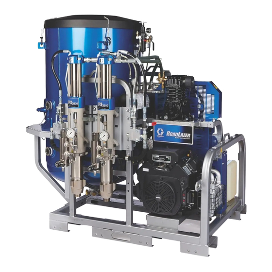
RoadLazer
HD Line Striping System
For the application of road marking and reflective coatings. For Professional Use Only.
List of Models (see page 2)
2900 psi (20 MPa, 200 bar) Maximum Working Pressure
Important Safety Instructions
Read all warnings and instructions in this manual and in related manuals.
Be familiar with the controls and the proper usage of the equipment.
Save these instructions.
Related Manuals:
3A5385
Repair
3A5386
Parts
™
RoadPak
www.graco.com/techsupport
™
& RoadPak
3A5384B
EN
Advertisement
Table of Contents

Related Manuals for Graco RoadLazer RoadPak


Summary of Contents for Graco RoadLazer RoadPak
- Page 1 2900 psi (20 MPa, 200 bar) Maximum Working Pressure Important Safety Instructions Read all warnings and instructions in this manual and in related manuals. Be familiar with the controls and the proper usage of the equipment. Save these instructions. Related Manuals: 3A5385 Repair 3A5386 Parts www.graco.com/techsupport...
-
Page 2: Complete Assemblies
Complete Assemblies Complete Assemblies Part Number Description 25D268 RoadPak System Option 1 (1, 6, 7, 10, 12) 25D269 RoadPak System Option 2 (1, 6, 7, 10, 11, 12) 25D270 RoadPak System Option 3 (1, 6, 7, 10, 12, 13, 14, 15) ... -
Page 3: Table Of Contents
RoadPak Installation .....10 Graco Information ......34 Gun Arm Bracket Mount . -
Page 4: Warnings
• This system is capable of producing 2900 psi (200 bar, 20 MPa). Use Graco parts or accessories that are rated a minimum of 2900 psi (200 bar, 20 MPa). - Page 5 Warnings WARNING WARNING WARNING EQUIPMENT MISUSE HAZARD Misuse can cause death or serious injury. • Do not operate the unit when fatigued or under the influence of drugs or alcohol. • Do not exceed the maximum working pressure or temperature rating of the lowest rated system com- ponent.
- Page 6 Warnings WARNING WARNING WARNING PERSONAL PROTECTIVE EQUIPMENT Wear appropriate protective equipment when in the work area to help prevent serious injury, including eye injury, hearing loss, inhalation of toxic fumes, and burns. Protective equipment includes but is not limited to: •...
-
Page 7: Introduction And General Information
The Laser Kit provides the user with a bright green line to fol- up to five stripes in one or two colors with glass beading. low for vehicle and spray gun alignment. The RoadLazer RoadPak consists of a Programmable Skipline Steerable Carriage Kit Controller, Displacement Pumps, two Paint Spray Guns, and two Bead Spray Guns. -
Page 8: Component Identification
Component Identification Component Identification 3A5384B... -
Page 9: Component Function
Component Function Component Function Air Regulator Allows regulation of the bead tank air pressure 36 gallon or 120 gallon bead tank. Holds reflective materials or element for sin- Bead Tank gle or double drop beading Air Accumulator Tank Helps maintain consistent air power to accessories Hydraulic Valve Valve to shut off/on the hydraulic fluid to the hydraulic motor Fluid Filter... -
Page 10: Setup
Setup Setup Charge Battery If the battery is newly purchased or has not been used for a long time, use a standard 12vdc automotive battery charger to charge it before use. Installation of RoadLazer into Vehicle ti16653a CRUSH HAZARD RoadLazer needs to be properly secured to prevent it from moving during transportation and operation. -
Page 11: Gun Arm Bracket Mount
Setup Filter Orientation 2. Tighten nut until the hitch insert bracket is pulled securely to the receiver and no play is seen After mounting and securing the RoadPak to the vehi- between the two parts. cle, position the filter assemblies as desired. 1. - Page 12 Setup RoadPak Mounting Bracket (24G627) 1. Slide the RoadPak mounting arms (304) between the two fork lift channels in the frame. Installation (Option 2) ti16917a 2. Depending on where the RoadPak is located on the vehicle determines which holes to bolt through on the RoadPak frame.
- Page 13 Setup 4. Install the height adjustment bracket (303) to the NOTE: It is recommended to bolt the mounting bracket RoadPak mounting arms (304) with bolts (312), through the bed of the vehicle and to the frame of the washers (307), and nuts (315). vehicle.
- Page 14 Setup Wide Orientation 3. Install the height adjustment bracket to the Road- Pak mounting arms (303). ti16921a ti16657a 1. Bolt brackets (316) to the RoadPak in four locations with bolts (312), washers (307), and nuts (315). It is ideal to locate the brackets as far apart as possible to provide optimal support.
- Page 15 Setup Slide Beam Installation (24G630) 5. Install stow-bracket (302) to height adjustment bracket (303). Locate the bottom of the The slide beam is 87.75 in. (2.2m) long. The Slide Beam stow-bracket 21 in. to 25 in. (53cm - 63cm) from the is shipped to accommodate wider vehicles.
- Page 16 Setup Gun Arm Installation (25M708, 25M709, 4. If necessary, adjust rollers to eliminate any play in the traverse bracket/gun arm carriage. Loosen roller 25M710) nuts just enough so that when the adjustment bolt is turned, the rollers will move in or out as desired. 1.
- Page 17 Setup 6. Position gun arm at the end of the slide beam and 8. Rest the gun arm on the stow bracket and position secure the hose bundle to the height adjustment the stop to sit properly on the stow bracket. Slide the bracket with a rubber pad and hose clamp (320).
-
Page 18: Hose Routing To Pumps And Tanks
Setup Hose Routing to Pumps and Tanks 3A5384B... - Page 19 Setup Hose Routing Hose Connection 1. Pull slide beam out to one side of the vehicle. Pull 1. Install suction tubes to the RPS 2900 pump and gun arm out and lower it to make sure the hose bun- route to paint drum or tote. dle has been secured at the proper location to ensure full movement for the gun arm to move from one side to the other.
- Page 20 Setup 4. Install bead lines to the bead tank. 2. Connect control cable to the junction box. Fasten cable to cable clamp for strain relief (SR) on the connection. 5. Install air hose from gun arm to quick connect fitting on air tank.
-
Page 21: Install Front Pointer Instructions
Setup Install Front Pointer Instructions 1. Locate an area on the vehicle to mount the Road- 5. Slide support bar (351) through brackets (355) and Pak pointer system that will allow the user to see the tighten fasteners to secure in place. indicator rod from the driving position or with the help of the Road View Camera System. -
Page 22: Operation
Operation Operation Grounding Procedure Pressure Relief Procedure (For Flammable Materials Only) Follow the Pressure Relief Procedure when- ever you see this symbol. The equipment must be grounded to reduce the risk of static sparking. Static sparking can cause fumes to ignite or explode. -
Page 23: Emergency Shut Off
Operation Air System Pressure Relief and 5. Close paint gun ball valves. Condensation Drain 1. Relieve air pressure and drain condensation in air tank by turning air valve to OPEN position. ti15953a ti16961a 6. Open all drain valves, one at a time. EMERGENCY SHUT OFF 7. -
Page 24: Set Up Slide Beam And Gun Arm
Operation Set Up Slide Beam and Gun Arm Prepare System to Paint 1. Unlock gun arm clamp and the slide beam clamps. NOTICE Paint could splash from the paint drum bung adapters when the paint drums are full and the vehicle is mov- ing. - Page 25 Operation 4. Fill fuel tank. 9. Turn valve lever by guns clockwise 1/4 turn to OFF position. 5. Check hydraulic oil level. Add only synthetic Hydraulic Oil, ISO 46 with a viscosity index (VI) of 154 or higher. Hydraulic tank capacity is approxi- mately 4.0 gallons (15.14 liters) for RoadPak mod- els and approximately 8.0 gallons (30.28 liters) for RoadPak HD models.
-
Page 26: Start Engine
Operation Select/Prime Pumps 13. Turn pressure control counterclockwise to lowest pressure. 1. Turn the bypass valve to RUN and open hydraulic valve(s) to activate pumps. 2. Slowly turn pressure control clockwise until pump begins to stroke. Start Engine 1. Set POWER ON/OFF on Programmable Skipline Controller to ON. - Page 27 Operation 4. Place suction hoses in paint drums. 2. Only open the spray gun ball valves corresponding to paint pumps and/or color to be used. ti16645a 5. Open hydraulic valve(s) to activate pumps. NOTE: Never open both ball valves on the two-color gun at the same time.
-
Page 28: Begin To Spray
Operation Turn on Bead System 2. Set desired bead tank pressure by turning regulator knob. 1. To pressurize the bead tanks, turn bead system valve to ON position. ti16910a 3. Remove and secure ground strap from earth ground. ti16549a 4. System is now ready for painting. Select guns with the Programmable Skipline Controller. -
Page 29: Flush The System
Operation Flush the System 8. Turn on Programmable Skipline Controller. NOTE: Unit will not start until Controller is turned ON. 9. Start Engine as follows: a. Set Choke ON (19 HP only). b. Set throttle to half speed. c. Turn key. The grounding clamp and ground strap are both d. - Page 30 Operation 13. Only open spray gun ball valves corresponding to 17. When water/solvent comes out of spray gun(s), set paint pumps or color used. paint pump hydraulic valve(s) to OFF position. NOTE: Never open both valves on the two-color gun at 18.
-
Page 31: Securing Gun Arm For Transportation
Operation Securing Gun Arm for 4. Slide the hitch pin through the gun arm bracket and stow bracket. Insert clip through pin. Transportation NOTE: Never transport the RoadLazer while the paint gun ball valves are open, the system is under pressure, and/or the engine is running, as this could cause damage to com- ponents. -
Page 32: Technical Data
Technical Data Technical Data RoadPak RoadPak HD US (Metric) US (Metric) Maximum Working Pressure Paint 2900 psi (200 bar) Hydraulics 1950 psi (134 bar) Glass bead system 75 psi (5 bar) Maximum paint flow 5 gpm (18.9 lpm)@ 2000 psi 10 gpm (37.9 lpm) @ 1600 psi (138 bar) (110 bar) -
Page 33: Graco Standard Warranty
With the exception of any special, extended, or limited warranty published by Graco, Graco will, for a period of twelve months from the date of sale, repair or replace any part of the equipment determined by Graco to be defective. -
Page 34: Graco Information
For patent information, see www.graco.com/patents. TO PLACE AN ORDER, contact your Graco distributor or call 1-800-690-2894 to identify the nearest distributor. All written and visual data contained in this document reflects the latest product information available at the time of publication.
Need help?
Do you have a question about the RoadLazer RoadPak and is the answer not in the manual?
Questions and answers