
Related Manuals for Ludlum Measurements 2241-2RK


Summary of Contents for Ludlum Measurements 2241-2RK
- Page 1 LUDLUM MODEL 2241-2RK RESPONSE KIT July 2012 Serial Number 237627 and Succeeding Serial Numbers...
- Page 2 LUDLUM MODEL 2241-2RK RESPONSE KIT July 2012 Serial Number 237627 and Succeeding Serial Numbers...
-
Page 4: Table Of Contents
Detector Model 44-9 Tube Replacement Procedure Radiation Basics Radiation and Life The Unstable Atom Radioactive Decay Ionizing Radiation Measuring Ionizing Radiation What are the Health Risks from Ionizing Radiation? How Much Ionizing Radiation is Dangerous? July 2012 Ludlum Measurements, Inc. - Page 5 Model 2241-2RK Technical Manual Background Radiation 6-10 Manmade Radiation 6-11 Protection from Radiation 6-11 Standards and Regulation 6-12 Who is in Charge? 6-12 Technical Principle of Operation Main Board Switch Board Display Board Instrument Setup & Calibration Factory Settings Entering or Changing Switch Board Parameters...
-
Page 6: Introduction
Section 1 Section Introduction he Model 2241-2RK is a first-responder kit that includes a portable microprocessor-based digital Scaler/ Ratemeter, as well as scintillation and Geiger-Mueller (GM) type detectors. It is designed for the rugged use of first responders in the measuring of ionizing radiation. - Page 7 Model 2241-2RK Technical Manual Section 1 Other features include: 1) Dead Time Correction (DTC) to compensate for detector dead time, 2) audible click-per-event with programmable 1, 10, 100, and 1000 divide-by; 3) LCD backlight with programmable time, 4) programmable fixed or variable response time, and 5) count overflow visual alarm, indicating that the counting circuitry is nearing the maximum counting capability.
- Page 8 Model 2241-2RK Technical Manual Section 1 The Response Kit’s sodium iodide (Nal) gamma scintillator, Model 44-2, is used for the detection of low-level gamma radiation, in the range of 50 keV- 1.5 MeV. The detector is energy dependant, over-responding by a factor of 10 or greater in the 100 keV range, and under- responding by a factor of 0.5 above 1 MeV when normalized to...
-
Page 9: Getting Started
The Model 2241-2 serial number is located on the front panel below the battery compartment. Most Ludlum Measurements, Inc. detectors have a label on the base or body of the detector for model and serial number identification. -
Page 10: Operational Check
Model 2241-2RK Technical Manual Section 2 Install two ˝D˝ size batteries in the compartment. Note the (+) and (–) marks inside the battery door. Match the battery polarity to these marks. Close the battery box lid. Note: The center post of a “D” size battery is positive. - Page 11 Model 2241-2RK Technical Manual Section 2 The display will auto-range to the current level (see figure at left). When auto-ranging down, the Model 2241-2 uses multiples of 5. This technique keeps the decimal point from jumping between numbers when viewing values around multiples of 10.
-
Page 12: Survey Techniques
Model 2241-2RK Technical Manual Section 2 Move the switch to the position. Depress SCALER RATEMETER SCALER switch located in the end of the carrying handle in order to COUNT initiate a count cycle. The word should be flashing on the LCD... - Page 13 Model 2241-2RK Technical Manual Section 2 Compare the first reading with the second to determine the amount of alpha and beta contribution. (This will be a very rough number.) : For gamma and high energy X-ray, the gamma Gamma and X-ray scintillator (Model 44-2) must be used.
-
Page 14: Specifications
Model 2241-2RK Technical Manual Section 3 Section Specifications : Readings are within 10% of true value with a detector Linearity Instrument connected. : Unit may be used immediately after the LCD Warm-up Time initialization sequence is completed (approximately five seconds after power-up). - Page 15 Model 2241-2RK Technical Manual Section 3 Note: button only silences the alarm in the current mode RESET that the instrument is in. For example, the button will RESET not affect the scaler alarm if the instrument is in the ratemeter mode.
- Page 16 Model 2241-2RK Technical Manual Section 3 : selects either 150, 300, 600, 1200, 2400, 4800, 9600, or Baud Rate 19200 bps : adjustable from 0 to 9999 Detector Dead Time Compensation (DTC) microseconds. : adjustable from 0.001 to 280 × 10...
- Page 17 Model 2241-2RK Technical Manual Section 3 : Active is 15 cm and open is 12 cm Window Area (4π geometry): typically 5% for C, 22% for Y, 19% for Efficiency Tc, 32% for P, and 15% for : typically 3300 cpm per mR/hr (...
-
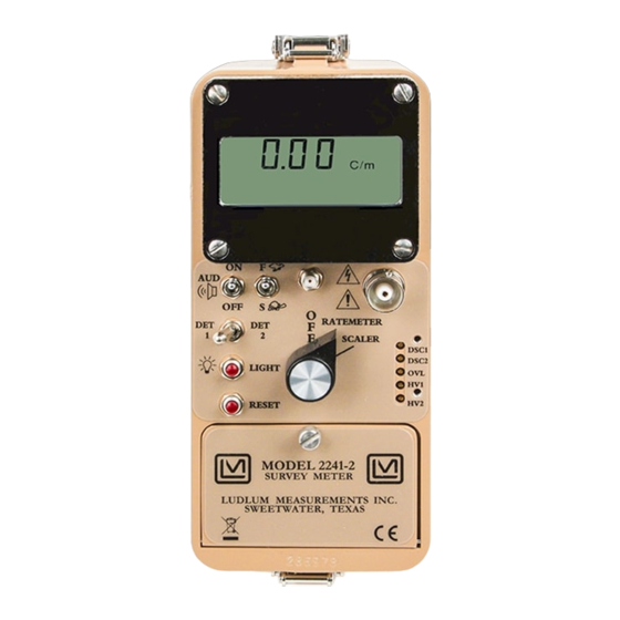
Page 18: Identification Of Controls And Functions
Model 2241-2RK Technical Manual Section 4 Section Identification of Controls and Functions Display The Model 2241-2 utilizes a four-digit liquid crystal display (LCD) with a two-digit overflow ( mode) and moving decimal point. The two SCALER smaller digits located in the lower right corner of the display indicate counter... -
Page 19: Front Panel Controls
Model 2241-2RK Technical Manual Section 4 mode when the six-digit display (four digits display and two overflow digits in right corner) reaches 999999 and starts to roll over again. : This indicates that the detector is being exposed to OVERLOAD radiation intensities greater than the detector maximum operating limit. -
Page 20: Front Panel Calibration Controls
Model 2241-2RK Technical Manual Section 4 : The position allows the time constant ( ) to Variable Response vary from 1 to 10 seconds, while the position varies from 1 to 30 seconds. The response time is automatically adjusted in proportion to the incoming count rate between the variables. -
Page 21: Main Board Controls
Model 2241-2RK Technical Manual Section 4 (Discriminator 1 and 2): two independent multi-turn DISC 1 and DISC 2 potentiometers (approximately 20 revolutions) used to vary the detector pulse-counting threshold from 2 to 100 millivolts for 1 and respectively. A Ludlum Model 500 Pulser or equivalent should be used in checking or adjusting the pulse discrimination parameter. -
Page 22: Switch Board Controls
Model 2241-2RK Technical Manual Section 4 : a multi-turn potentiometer (approximately 20 VOLUME (R002) revolutions) varies the audible click-per-event and alarm audio. Adjust the control to the maximum clockwise position for maximum volume. If the control is adjusted to the maximum counterclockwise... -
Page 23: Safety & Maintenance Considerations
Model 2241-2RK Technical Manual Section 5 Section Safety & Maintenance Considerations Environmental Conditions for Normal Use Indoor or outdoor use Maximum altitude of 2438 meters (8000 feet) above sea level Temperature range of –20 to 50°C (-4 to 122 °F) Maximum relative humidity of less than 95% (non-condensing) Pollution Degree 1 (as defined by IEC 664). -
Page 24: Maintenance
Model 2241-2RK Technical Manual Section 5 The Model 2241-2 Survey Meter is marked with the following symbols: CAUTION, RISK OF ELECTRIC SHOCK (per ISO 3864, No. B.3.6): designates a terminal (connector) that allows connection to a voltage exceeding 1 kV. Contact with the subject connector while the instrument is on or shortly after turning off may result in electric shock. -
Page 25: Operational Check
Check the appropriate local state and federal regulations to determine required recalibration intervals. Ludlum Measurements offers a full-service repair and calibration department. We not only repair and calibrate our own instruments but most other manufacturer’s instruments as well. -
Page 26: Detector Model 44-9 Tube Replacement Procedure
Model 2241-2RK Technical Manual Section 5 44-9 T ETECTOR ODEL EPLACEMENT ROCEDURE Consult the Model 44-9 Alpha-Beta-Gamma Detector drawing in Section 11 of this manual to perform the following: Caution! The mica window of this tube is extremely thin and can easily break. -
Page 27: Radiation Basics
Model 2241-2RK Technical Manual Section 6 Section Radiation Basics Radiation and Life Adapted from Eric J. Hall’ s book, “Radiation and Life” Radiation is energy traveling through space. Sunshine is one of the most familiar forms of radiation. It delivers light, heat, and suntans. We control its effect on us with sunglasses, shade, air conditioners, hats, clothes, and sunscreen. -
Page 28: The Unstable Atom
Model 2241-2RK Technical Manual Section 6 The Unstable Atom Radiation comes from atoms, the basic building blocks of matter. Most atoms are stable; a C atom, for example, remains a C atom forever, and an O atom remains an O atom forever, but certain atoms eventually disintegrate into a totally new atom. -
Page 29: Radioactive Decay
Model 2241-2RK Technical Manual Section 6 1 kg (2.2 lb) of uranium ore (Australian, 13.51 X 10 0.3%) 1 kg (2.2 lb) of low-level radioactive waste 27.03 X 10 1 kg (2.2 lb) of coal ash 5.41 X 10 1 kg (2.2 lb) of granite 2.70 X 10... -
Page 30: Ionizing Radiation
Model 2241-2RK Technical Manual Section 6 The shorter-lived each kind of radioisotope, the more radiation it emits per unit mass. Much of the natural radioactivity in rocks and soil comes from this decay chain. Ionizing Radiation Here we are concerned mainly with ionizing radiation from the atomic nucleus. -
Page 31: Measuring Ionizing Radiation
Model 2241-2RK Technical Manual Section 6 their relatively large size, alpha particles collide readily with matter and lose their energy quickly. They therefore have little penetrating power and can be stopped by the first layer of skin or a sheet of paper. -
Page 32: What Are The Health Risks From Ionizing Radiation
Model 2241-2RK Technical Manual Section 6 The amount of ionizing radiation, or dose, received by a person is measured in terms of the energy absorbed in the body tissue, and is expressed in RAD. One rad is 0.01 joules deposited per kilogram of mass. -
Page 33: How Much Ionizing Radiation Is Dangerous
Model 2241-2RK Technical Manual Section 6 On the other hand, large doses of radiation directed specifically at a tumor are used in radiation therapy to kill cancerous cells, and thereby often save lives (usually in conjunction with chemotherapy or surgery). Much larger doses are used to kill harmful bacteria in food, and to sterilize bandages and other medical equipment. - Page 34 Model 2241-2RK Technical Manual Section 6 2 rem/yr averaged over 5 years is the limit for radiological personnel such as employees in the nuclear industry, uranium or mineral sands miners, and hospital workers (who are all closely monitored). 1 rem/yr is the maximum actual dose rate received by any Australian uranium miner.
- Page 35 Model 2241-2RK Technical Manual Section 6 where given a set population, we can estimate that about 20 percent will die from cancer, but we cannot say which individuals will die. Finally, that a conservative estimate of risk from low doses of radiation is thought to be one in which the risk is linear with dose.
-
Page 36: Background Radiation
Model 2241-2RK Technical Manual Section 6 You can also use the same approach to looking at risks on the job: Industry Type Est. life expectancy lost All Industries 60 days Agriculture 320 days Construction 227 days Mining and quarrying 167 days... -
Page 37: Manmade Radiation
Model 2241-2RK Technical Manual Section 6 up to a couple thousand rem. However, there is no evidence of increased cancers or other health problems arising from these high natural levels. Manmade Radiation Ionizing radiation is also generated in a range of medical, commercial, and industrial activities. -
Page 38: Standards And Regulation
Model 2241-2RK Technical Manual Section 6 Standards and Regulation Much of the evidence that has led to today's standards derives from the atomic bomb survivors in 1945, which were exposed to high doses incurred in a very short time. In setting occupational risk estimates, some allowance... -
Page 39: Technical Principle Of Operation
Model 2241-2RK Technical Manual Section 7 Section Technical Principle of Operation Refer to the Main Detector Input/Amplifier Board schematic for the following: Negative-going detector pulses are coupled from the detector through C021 to Amplifier U021. R024 and CR021 protect the input of U021 from inadvertent shorts. - Page 40 Model 2241-2RK Technical Manual Section 7 High Voltage Supply High voltage is developed by blocking oscillator Q241, T141, and C244 and rectified by voltage multiplier CR041-CR043, C041-C043, and C141. High voltage increases as current through R241 increases, with maximum output voltage with Q241 saturated.
- Page 41 Model 2241-2RK Technical Manual Section 7 Refer to the Switch Board schematic for S1 (FUNCTION) the following: S1 is a 16-position binary rotary switch, which selects the programmable parameters for the Model 2241-2. The switch selects the parameters using the hexadecimal numbering system via buss lines...
-
Page 42: Switch Board
Model 2241-2RK Technical Manual Section 8 Section Instrument Setup & Calibration Factory Settings If special calibration requirements are not specified at the time the instrument is ordered, calibration will be made based on the default settings shown below: DET#1 DET#2... -
Page 43: The Function Switch
Model 2241-2RK Technical Manual Section 8 Once the desired data is entered, depress the button. The LCD ENTER characters should stop flashing, and the new parameter data should display. Note: toggle switch allows the Model 2241-2 DETECTOR SELECT to have two sets of operating parameters. - Page 44 Model 2241-2RK Technical Manual Section 8 Where, 1 - mτ n = corrected counts per second m = incoming count per second τ = system dead time allows changing the calibration POSITION 2 CALIBRATION CONSTANT cps x time base constant for the current detector setup. The calibration constant (CC)
- Page 45 Model 2241-2RK Technical Manual Section 8 (position 1). The Model 2241-2 will automatically convert to the correct reading when switching between R and Sv. The time base for count “C” is set independently in position 4. The display units may be set to:...
- Page 46 Model 2241-2RK Technical Manual Section 8 selects the audible clicks-per-event POSITION 5 AUDIO DIVIDE BY division rate for the current detector setup. If the switch is AUD ON in the position, no audible clicks-per-event will be heard. This parameter ranges from:...
- Page 47 Model 2241-2RK Technical Manual Section 8 POSITION A NOT USED : LCD Backlight is the amount of time that the LCD POSITION B ON TIME backlight will stay on after pressing the front-panel switch labeled LIGHT This value is stored in EEPROM.
-
Page 48: Calibration
DATA IN HANDSHAKING IN HANDSHAKING OUT Note: Ludlum Measurements, Inc. offers a PC compatible software program that incorporates the read/write commands necessary to communicate between the PC and the Model 2241-2. The program also incorporates an algorithm to calculate the detector Calibration Constant and Dead Time Constant. -
Page 49: General Detector Setup Information
The counts per minute parameter setup is used in the initial instrument checkout procedure, and the variables are saved under detector setup number “1” when shipped from Ludlum Measurements, Inc. The following subsection deals with exposure rate calibration. The detector Calibration Constant (CC) and Dead Time Correction (DTC) are the two primary parameters used in the exposure rate calibrations (R/hr and Sv/h). -
Page 50: Counts Per Minute (C/M) Calibration
Model 2241-2RK Technical Manual Section 8 For most GM detectors, set for 30-40 millivolts and adjust DISC the GM detector recommended high voltage. Most GM detectors operate at 900 volts, although some miniature detectors operate at 450-550 volts. If a recommended setting is unavailable, plot count rate versus HV to produce a plateau graph. - Page 51 Model 2241-2RK Technical Manual Section 8 Switch to the position. SCALER RATEMETER RATEMETER Select position 1 on the rotary switch located on the front panel. Select switch positions 1-6 and adjust for the FUNCTION following parameters: Switch Pos. Parameter Function...
-
Page 52: R/Hr Calibration
Model 2241-2RK Technical Manual Section 8 Adjust the pulser amplitude to 1.5 times the Model 2241-2 discrimination level. Adjust the pulser output to 800 cpm and confirm that the Model 2241-2 reads 800 cpm ±10% on the ratemeter setting. - Page 53 Ludlum Model 44-9 GM detector calibration is used in conjunction with the algorithm calculations to aid in solving the equations. Note: Ludlum Measurements, Inc. offers a PC-compatible software program that incorporates the read/write commands necessary to communicate between a PC and the Model 2241-2.
- Page 54 Model 2241-2RK Technical Manual Section 8 Preliminary CPS Setup Refer to Section 8, Subsection “Function Switch Position Descriptions and Variables,” for cps readout variables. Select position 1 on the toggle switch located on the front panel. Starting with switch position 1, enter the following variables: FUNCTION SWITCH POS.
- Page 55 Model 2241-2RK Technical Manual Section 8 Reference the table at the end of this section to determine the cps/exposure rate (cps/ER). The conversion can be determined by placing the detector in a radiation field which produces from 50 to 200 cps.
- Page 56 Model 2241-2RK Technical Manual Section 8 CC and DTC Algorithm Equations (5) and (6) convert units per time (R/hr Display Units) to units per second: uni t s uni t s ⇒ t i m e second Insert the cps lo data point (8 mR/hr for the Model 44-9 example)
- Page 57 Model 2241-2RK Technical Manual Section 8 As an example, assume a 60-second count sample in a low field of 8 mR/hr: Example 26,427 CORR Place detector in the high field and enter the counts per second: Equation 8 counts SAMPL...
- Page 58 Model 2241-2RK Technical Manual Section 8 Enter the results of equations (9) and (10) into equation (11) to solve for Equation 11 count Example − − − Solve for f Equation 12 units CORR Example − − − − 2.22 (2.22...
- Page 59 Model 2241-2RK Technical Manual Section 8 Model 44-9 Detector Parameter Setup FUNCTION PARAMETER 0084 s 0206 as desired as desired if applicable Typical Count Rate and Dead Time for LMI Detectors DEAD TIME MODEL & TYPE COUNT RATE in µs (microseconds)
-
Page 60: Detector Overload (Ovl) Calibration
Model 2241-2RK Technical Manual Section 8 (OVL) C ETECTOR VERLOAD ALIBRATION Note: The detector operating voltage (HV) must be determined and adjusted before the adjustment is performed. If the HV is varied or another detector is substituted, must be readjusted. If the overload feature is not used, adjust the control to the maximum counterclockwise position. -
Page 61: Loading Default Parameters
Model 2241-2RK Technical Manual Section 8 The detector overload or saturation point for alpha and/or beta scintillation detectors is when the detector face (Mylar) has been punctured, allowing light to saturate the photomultiplier tube (PMT). The pulse output will decrease or even appear non-responsive to any radiation activity, depending upon the size of the puncture and the light intensity to the PMT. - Page 62 Model 2241-2RK Technical Manual Section 8 Page 8-21 July 2012 Ludlum Measurements, Inc.
- Page 63 Model 2241-2RK Technical Manual Section 8 Page 8-22 July 2012 Ludlum Measurements, Inc.
- Page 64 Model 2241-2RK Technical Manual Section 8 Page 8-23 July 2012 Ludlum Measurements, Inc.
-
Page 65: Recycling
To this end, Ludlum Measurements, Inc. strives to supply the consumer of its goods with information regarding reuse and recycling of the many different types of materials used in its products. With many different agencies –... -
Page 66: Parts List
Model 2241-2RK Technical Manual Section 10 Section Parts List Reference Description Part Number Model 2241-2 UNIT Completely Assembled Survey Meter Model 2241-2 Survey Meter 48-2731 BOARD Completely Assembled Main Circuit Board, Main Circuit Board 5408-223 Drawing 408 × 223 CAPACITORS 0.1µF, 50V... - Page 67 Model 2241-2RK Technical Manual Section 10 Reference Description Part Number C241 1µF, 35V 04-5656 C242 68µF, 10V 04-5654 C243 0.1µF, 50V 04-5663 C251 68µF, 10V 04-5654 TRANSISTORS Q101 2N7002L 05-5840 Q141 MMBT3904LT1 05-5841 Q211 2N7002L 05-5840 Q212 MMBT4403LT1 05-5842 Q241...
- Page 68 Model 2241-2RK Technical Manual Section 10 Reference Description Part Number R023 10K, 1/4W, 1% 12-7839 R024-R025 4.75K, 1/4W, 1% 12-7858 R026 8.25K, 1/8W, 1% 12-7838 R031 4.7M, 1/4W, 5% 10-7030 R032 1M, 1/4W, 5% 10-7028 R033-R034 1G, FHV-1, 2% 12-7686 R111-R113 22.1K, 1/4W, 1%...
- Page 69 Model 2241-2RK Technical Manual Section 10 Reference Description Part Number R112 1M, OVERLOAD 09-6814 R113 100K, DISC 2 09-6813 R114 100K, DISC 1 09-6813 R115 1M, 1/3W 12-7751 RESISTORS R116 1K, 1/3W 12-7750 R118 10K, 1/3W 12-7748 R119 1M, 1/3W...
- Page 70 Model 2241-2RK Technical Manual Section 10 Reference Description Part Number Switch Board, BOARD Completely Assembled Drawing 408 × 45 Switch Board 5408-052 CAPACITORS C1-C2 4.7µF, 10V 04-5578 C3-C4 10µF, 20V 04-5592 4.7µF, 10V 04-5578 100µF, 10V 04-5576 MAX220EPE 06-6359 INTEGRATED CIRCUITS 350134GSK;...
- Page 71 Model 2241-2RK Technical Manual Section 10 Reference Description Part Number JACK-09-9011-1-4193 18-9080 Handle Pin 7408-055 UNIMORPH 21-9251 AUDIO B1-B2 ˝D˝ Duracell Battery 21-9313 BATTERY Model 2241 MISCELLANEOUS Switch Board Add On 4408-053 Model 2240 Digital Bezel Assembly 4408-020 Bezel Back...
- Page 72 Model 2241-2RK Technical Manual Section 10 Reference Description Part Number UNIT Completely Assembled Model 44-9 Alpha-Beta- Model 44-9 Alpha-Beta- Gamma Detector Gamma Detector 47-1539 (PANCAKE), Drawing 2 x 206 DETECTOR BODY 2002-109 HANDLE GRIP 7002-426 GM TUBE (LND 7311) TGM N1002...
-
Page 73: Main Circuit Board, Drawing 408 × 223
Model 2241-2RK Technical Manual Section 11 Section Drawings Main Circuit Board, Drawings 408 × 223 (3 sheets) Main Circuit Board Component Layout, Drawing 408 × 224 Calibration Board, Drawing 408 × 127 Calibration Board Component Layout, Drawings 408 × 128 (2 sheets) Display Board, Drawing 408 ×... - Page 74 Model 2241-2RK Technical Manual Section 11 Model 44-2 Gamma Scintillator Assembly View, Drawing 2 x 205A 1.5 in. Tube Socket Board Schematic, Drawing 2 x 317 1.5 in. Tube Socket Board Component Layout, Drawing 2 x 318 Energy Response Curve Model 44-2...
- Page 89 Gamma Energy Response for Ludlum Model 44-9...
Need help?
Do you have a question about the 2241-2RK and is the answer not in the manual?
Questions and answers