
Related Manuals for Ludlum Measurements 2242


Summary of Contents for Ludlum Measurements 2242
- Page 1 LUDLUM MODEL 2242 SURVEY METER November 2010 Serial Number 219764 and Succeeding Serial Numbers...
- Page 2 LUDLUM MODEL 2242 SURVEY METER November 2010 Serial Number 219764 and Succeeding Serial Numbers LUDLUM MEASUREMENTS, INC. 501 OAK STREET, P.O. BOX 810 SWEETWATER, TEXAS 79556 325-235-5494, FAX: 325-235-4672...
- Page 3 RETURN OF GOODS TO MANUFACTURER If equipment needs to be returned to Ludlum Measurements, Inc. for repair or calibration, please send to the address below. All shipments should include documentation containing return shipping address, customer name, telephone number, description of service requested, and all other necessary information.
-
Page 4: Table Of Contents
Recalibration Batteries Setup and Calibration Entering or Changing Switch Board Parameters The Function Switch Function Switch Position Descriptions and Variables Calibration General Detector Setup Information Exposure Rate Calibration Detector Overload (OVL) Calibration Loading Default Parameters November 2010 Ludlum Measurements, Inc. - Page 5 MODEL 2242 Technical Manual Troubleshooting Technical Principle of Operation Recycling Parts List Model 2242 Survey Meter 10-1 Main Board, Drawing 408 × 223 10-1 Calibration Board, Drawing 408 × 229 10-3 Display Board, Drawing 408 × 79 10-4 Switch Board, Drawing 408 × 46 10-4 Wiring Diagram, Drawing 408 ×...
-
Page 6: Introduction
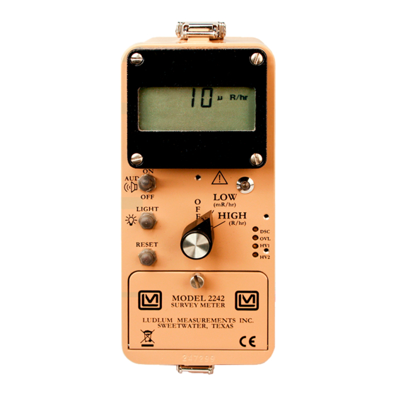
Technical Manual Section 1 Section Introduction he Model 2242 is a portable microprocessor-based digital Ratemeter designed for detection and measurement of ionizing radiation. The data is presented on a 4-digit Liquid Crystal Display (LCD). A 3- position switch labeled “... - Page 7 MODEL 2242 Technical Manual Section 1 The instrument operates on two ˝D˝ cell flashlight batteries. The unit body is made of cast-and-drawn aluminum and is covered in beige powder- coating to aid in surface decontamination. Page 1-2 November 2010 Ludlum Measurements, Inc.
-
Page 8: Getting Started
(batteries, cables, etc.) and ensure that all of the items listed on the packing list are in the carton. Check individual item serial numbers and ensure calibration certificates match. The Model 2242 serial number is located on the front panel below the battery compartment. -
Page 9: Operating The Instrument
(with the exception of a single discrimination parameter). The Model 2242 incorporates a detachable switch board used to program detector and operating parameters into non-volatile memory (retains the data even after the power is removed). The switch board may be removed so that the operating parameters cannot be altered. - Page 10 MODEL 2242 Technical Manual Section 2 An LCD provides the readout for the ratemeter data with the programmed units and multipliers, as well as ALERT ALARM annunciators, OVERLOAD OVERFLOW "low battery" icon, and scaler counting mode indication ( – not used). The four 0.5" digits are used for COUNTING the ratemeter data.
-
Page 11: Specifications
MODEL 2242 Technical Manual Section 3 Section Specifications : Two standard "D" size batteries; current drain approx. 35 mA POWER (backlight off); minimum battery voltage 2.2 ± 0.1 Vdc : Instrument calibration change less than 3% to BATTERY DEPENDENCE battery endpoint... - Page 12 MODEL 2242 Technical Manual Section 3 : Separate visual and audible adjustable alarm points for ALERT/ALARM both the mR/hr and R/hr ranges : Adjustable from 2-100 mV; negative pulse INPUT SENSITIVITY response. Normally set at approximately 90 mV for the internal detectors : Externally adjustable from 400 to 2500 volts;...
-
Page 13: Description Of Controls And Functions
RESET and/or alert condition. Depressing the scaler count switch located in the end of the Model 2242 handle resets the scaler alarm only. Remove the front panel CAL cover to access the following controls: : A multi-turn potentiometer (approximately 20... -
Page 14: Internal Controls
To access the internal circuit boards, unlatch the latches at each end of the Model 2242. Carefully separate the top chassis from the bottom cover (referred to as a ˝can˝). The can has the audio speaker (unimorph) with a 2- conductor cable attached to the main board. -
Page 15: Display
16 setup parameters. (Refer to schematics and component layout drawing near the end of the manual.) All setup parameters are stored in the non-volatile EEPROM, which will retain data even after the Model 2242 batteries are removed. After parameters are entered the switch board can be... - Page 16 MODEL 2242 Technical Manual Section 4 - Indicates that the detector is being exposed to radiation OVERLOAD intensities greater than the detector maximum operating limit. The overload alarm point is set by adjusting the control located underneath the cover. - Indicates that the batteries have decreased to the "low battery"...
-
Page 17: Safety & Maintenance Considerations
Pollution Degree 1 (as defined by IEC 664) Cleaning Instructions and Precautions The Model 2242 Scaler/Ratemeter may be cleaned externally with a damp cloth, using only water as the wetting agent. Do not immerse the instrument in any liquid. Observe the following precautions when cleaning: 1. -
Page 18: Maintenance
The Model 2242 instrument may be cleaned with a damp cloth (using only water as the wetting agent). Do not immerse instrument in any liquid. Observe the following precautions when cleaning: 1. -
Page 19: Recalibration
Check the appropriate regulations to determine required recalibration intervals. Ludlum Measurements offers a full service repair and calibration department. We not only repair and calibrate our own instruments but most other manufacturer’s instruments. Calibration procedures are available upon request for customers who choose to calibrate their own instruments. -
Page 20: Setup And Calibration
A 16-position rotary switch labeled ˝0-9˝ and ˝ ˝. This switch selects a parameter setup mode for the Model 2242. If the board is not installed, the normal operation mode (counting mode) is selected. If the switch board is installed, the selector switch must be set to the ˝0˝ position for normal operation. - Page 21 Section 6 o Once the desired data is entered, depress . The LCD stops ENTER flashing and the new parameter data is displayed. Note: switch allows the Model 2242 to have 2 HIGH sets of operating parameters. UNCTION WITCH OSITION...
- Page 22 ) for POSITION 6 RESPONSE TIME the current detector setup. If the response is set to ˝0˝ the Model 2242 automatically calculates (for variable mode), the time constant based on the incoming cps. If a variable of 1-199 is entered for , the response time becomes fixed.
-
Page 23: Calibration
550 Vdc and 460 Vdc, and instrument sensitivity ( ) of 90 mV. DISC XPOSURE ALIBRATION To calibrate the Model 2242 to exposure rate after setting the potentiometers, start with the following values for (Dead Time, DISC Switch Position 1) and (Calibration Constant, Switch Position 2). -
Page 24: Detector Overload (Ovl) Calibration
MODEL 2242 Technical Manual Section 6 For exposure rate calibrations, use a calibrated Cs source, and set the Model 2242 to ˝mR/hr˝. Place the detector at the following points: mR/hr µR/hr 8* adjust CC 8* adjust CC 200* adjust DT... -
Page 25: Loading Default Parameters
MODEL 2242 Technical Manual Section 6 Place the detector in an increasing radiation field in which the readout no longer increases. Adjust the control until the OVERLOAD OVERLOAD alarm appears. Position the detector between the upper operating limit and the overload set point and ensure the overload alarm is defeated. -
Page 26: Troubleshooting
MODEL 2242 Technical Manual Section 7 Section Troubleshooting ccasionally, you may encounter problems with your LMI instrument or detector that may be repaired or resolved in the field, saving turnaround time and expense in returning the instrument to us for repair. Toward that end, LMI electronics technicians offer the following tips for troubleshooting the most common problems. - Page 27 MODEL 2242 Technical Manual Section 7 SYMPTOM POSSIBLE SOLUTION No power, or low Check battery contacts. Clean them battery icon displays with rough sandpaper or use an (continued) engraver to clean the tips. Check for loose or broken wires, especially between the main board and the calibration board.
- Page 28 MODEL 2242 Technical Manual Section 7 SYMPTOM POSSIBLE SOLUTION No Audio Ensure the switch is in AUD ON position. Remove the instrument housing and check the connection between the circuit board and the speaker. Plug in the 2-pin connector if necessary.
-
Page 29: Technical Principle Of Operation
MODEL 2242 Technical Manual Section 8 Section Technical Principle of Operation Refer to the Main Board Schematic, Drawing 408 × 223 for the following: Detector Input/ Amplifier Negative-going detector pulses are coupled from the detector through C021 to Amplifier U021. R024 and CR021 protect the input of U021 from inadvertent shorts. - Page 30 MODEL 2242 Technical Manual Section 8 U231 provides a low signal when the battery voltage decreases to +2.2 ±0.1Vdc. U121 provides the +2.5Vdc reference for the control DISC references. High Voltage Supply High Voltage is developed by blocking oscillator Q241, T141, and C244 and rectified by voltage multiplier CR041-CR043, C041-C043, and C141.
- Page 31 MODEL 2242 Technical Manual Section 8 Audio Click/event, divide-by, and alarm audio pulse frequency is generated by the µP and coupled to Q101. Q101 then inverts the pulses and drives the bottom of T101. Bias voltage is provided by the volume control (R002) to the top of T101.
- Page 32 MODEL 2242 Technical Manual Section 8 Backlight Drive Depressing the switch instructs the µP to set the line, pin LIGHT BACKLIGHT 31 on µP, "low" for the predetermined backlight time. (Refer to main board schematic for details.) A "low" condition on pin 31 causes Q212 to conduct sending +3V to P8-3 on display board.
-
Page 33: Recycling
To this end, Ludlum Measurements, Inc. strives to supply the consumer of its goods with information regarding reuse and recycling of the many different types of materials used in its products. With many different agencies, public and private, involved in this pursuit it becomes evident that a myriad of methods can be used in the process of recycling. -
Page 34: Parts List
Technical Manual Section 10 Section Parts List Reference Description Part Number Model 2242 UNIT Completely Assembled Survey Meter Model 2242 Survey Meter 48-3437 BOARD Completely Assembled Main Board, Main Board 5408-223 Drawing 480 × 223 Y221 MICRO X-TAL-6.144 MHZ 01-5262... - Page 35 MODEL 2242 Technical Manual Section 10 Reference Description Part Number C243 0.1uF, 50V 04-5663 C251 68uF, 10V 04-5654 Q101 2N7002L 05-5840 TRANSISTORS Q141 MMBT3904T 05-5841 Q211 2N7002L 05-5840 Q212 MMBT4403LT 05-5842 Q241 MJD210 05-5843 INTEGRATED MAX810 06-6424 CIRCUITS U001 CD74HC4538M...
- Page 36 MODEL 2242 Technical Manual Section 10 Reference Description Part Number R033-R034 12-7686 R111-R113 22.1K, 1/4W, 1% 12-7843 R121 100 Ohm, 1/8W, 1% 12-7840 R122 6.81K, 1/4W, 1% 12-7857 R131-R132 1 M, 1/4W, 1% 12-7844 R133 750K, 1/4W, 1% 12-7882 R134...
- Page 37 MODEL 2242 Technical Manual Section 10 Reference Description Part Number BOARD Completely Assembled Display Board, Display Board 5408-091 Drawing 408 × 79 C012 27pF, 100V 04-5658 CAPACITORS C113 47pF, 100V 04-5660 U111 AY0438-I/L 06-6358 INTEGRATED CIRCUITS U114 SP4422N 06-6399 U211...
- Page 38 MODEL 2242 Technical Manual Section 10 Reference Description Part Number Wiring Diagram, 30-1-PB GRAYHILL 08-6517 Drawing 408 × 221 7101-SYZ-QE C&K 08-6511 SWITCHES 30-1-PB GRAYHILL 08-6517 PA-600-210 08-6501 1-640442-2 MTA100 13-8407 CONNECTORS 1-640442-3 MTA100 13-8138 640442-6 MTA100 13-8171 640442-2 MTA100...
- Page 39 MODEL 2242 Technical Manual Section 10 Reference Description Part Number Portable Knob 08-6613 Assembled Screened Battery Lid 9408-218 Portable Battery Gasket 7363-183 Portable Calibration Cover w/Screws 9363-200 Portable Handle Assembly 7363-139 (OPTIONAL) Check Source (1µCi Cs-137) 01-5196 Page 10-6 November 2010...
-
Page 40: Main Board, Drawing 408 × 223
Technical Manual Section 11 Section Drawings and Diagrams M 2242 SIDE VIEW, Drawing 408 × 219C MAIN BOARD, Drawing 408 × 223 (3 sheets) MAIN BOARD LAYOUT, Drawing 408 × 224 CALIBRATION BOARD, Drawing 408 × 229 CALIBRATION BOARD LAYOUT, Drawing 408 × 230 (2 Sheets) DISPLAY BOARD, Drawing 408 ×...
Need help?
Do you have a question about the 2242 and is the answer not in the manual?
Questions and answers