
Related Manuals for Ludlum Measurements 78


Summary of Contents for Ludlum Measurements 78
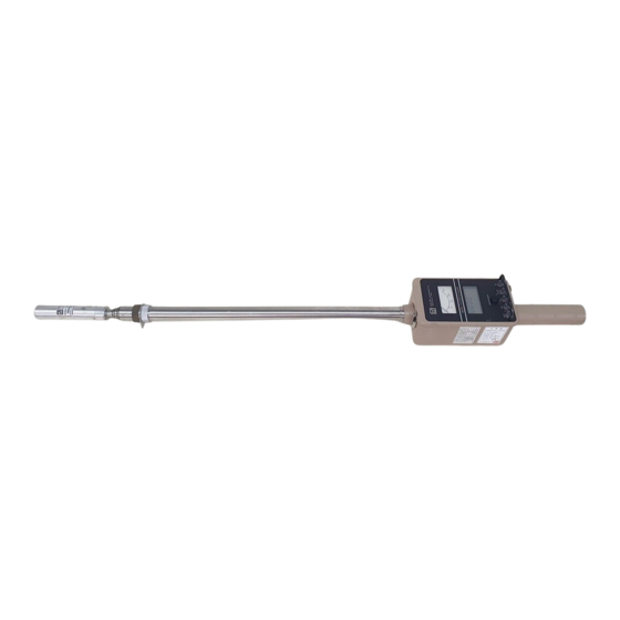
- Page 1 LUDLUM MODEL 78 AND 78-1 DIGITAL ANALOG STRETCH SCOPE March 2021 Serial Number 299335 and Succeeding Serial Numbers...
- Page 2 LUDLUM MODEL 78 AND 78-1 DIGITAL ANALOG STRETCH SCOPE March 2021 Serial Number 299335 and Succeeding Serial Numbers...
- Page 3 RETURN OF GOODS TO MANUFACTURER If equipment needs to be returned to Ludlum Measurements, Inc. for repair or calibration, please send to the address below. All shipments should include documentation containing return shipping address, customer name, telephone number, description of service requested, and all other necessary information.
-
Page 8: Table Of Contents
Environmental Conditions for Normal Use Warning Markings and Symbols Cleaning and Maintenance Precautions Maintenance Recalibration Batteries Technical Theory of Operation Detector Input/Amplifier Discriminator Low Voltage Supply High Voltage Supply Detector Overload Microprocessor Audio S1 (Function) S2-S4 Ludlum Measurements, Inc. March 2021... - Page 9 Calibration General Detector Setup Information Exposure Rate Calibration Detector Overload (OVL) Calibration Recycling Parts List Model 78 Digital Analog Stretch Scope 10-1 Main Circuit Board, Drawing 272 x 591 10-1 Cal/Switch Board, Drawing 272 × 352 10-3 Display Board, Drawing 408 × 259 10-4 Chassis Wiring Diagram, Drawing 272 ×...
-
Page 10: Introduction
3.7 m (12 ft) extendable pole. The two energy- compensated, Geiger-Mueller (GM) detectors measure gamma radiation from 0.1 mR/hr mR/hr to 1000 R/hr (1µSv/h – 10,000mSv/h). The Model 78 measures in R (Roentgen) (Roentgen) units while the 78-1 measures in Sieverts. -
Page 11: Getting Started
Check individual item serial numbers and ensure calibration certificates match. The Model 78 serial number is located on the front panel above the analog meter face. Most Ludlum Measurements, Inc. detectors have a label on the base or body of the detector for model and serial number identification. -
Page 12: Operational Check
The LCD then shows the firmware number in the format “P XX YY.” The “XX” is the firmware number, and the “YY” is the firmware version. (The following figure is for example only, to illustrate location of display.) Note: The Model 78 is not sensitive to neutron radiation. Ludlum Measurements, Inc. Page 2-2 March 2021... - Page 13 FAST Note: The slow response position is normally used when the Model 78 is displaying low numbers that require a more stable display. The fast response is used at high count levels. Depress and release the switch.
-
Page 14: Specifications
Model 78 and 78-1 Technical Manual Section 3 Section Specifications : 4-digit LCD with 1.3 cm (0.5 in.) character height DISPLAY 0.1 to 999.9 mR/hr Model 78 RANGE: 1 µSv/h to 9999 mSv/h Model 78-1 RANGE: : within 10% of true value with connected detector DISPLAY LINEARITY : adjustable from 2-100 mV;... - Page 15 Model 78 and 78-1 Technical Manual Section 3 : unit may be used immediately after the LCD initialization sequence is WARM-UP TIME completed – approximately five seconds after turning on : visual and audible adjustable alarm points ALERT/ALARM : 0.001 to 280 × 10...
-
Page 16: Identification Of Controls And Functions
Identification of Controls and Functions Display The Model 78 utilizes a four-digit LCD readout with a fixed decimal point. The two smaller digits located in the lower right corner of the display indicate exponential power when in the parameter setup mode. The upper right of the LCD exhibits units and multiplier(s) R/hr, mR/hr, or µR/hr;... -
Page 17: Front Panel Controls
To access the internal circuit boards, unlatch the latches at each end of the Model 78. Carefully separate the top chassis from the bottom cover (referred to as a "can"). The can has the audio speaker (unimorph) with a two- conductor cable attached to the main board. -
Page 18: Cal/Switch Board Controls
Model 78 and 78-1 Technical Manual Section 4 : a multi-turn potentiometer (approximately 20 revolutions) sets the HV LIMIT (R027) maximum HV limit with the front-panel control adjusted to the maximum clockwise position. It is adjustable from 1250 to 2400 Vdc. - Page 19 All of the setup parameters are stored in the non-volatile EEPROM, which will retain data even after the Model 78 batteries are removed. Changing parameters and information on switchboard controls, other than those detailed above, are covered in Section 8 of this manual.
-
Page 20: Safety Considerations
Model 78 and 78-1 Technical Manual Section 5 Section Safety Considerations Environmental Conditions for Normal Use Indoor or outdoor use No maximum altitude Temperature range of -20 to 50 °C (-4 to 122 °F); may be certified for operation from -40 to 65 °C (-40 to 150 °F) Maximum relative humidity of less than 95% (non-condensing) Pollution Degree 3 (as defined by IEC 664). -
Page 21: Cleaning And Maintenance Precautions
European Union. Cleaning and Maintenance Precautions The Model 78 may be cleaned externally with a damp cloth, using only water as the wetting agent. Do not immerse the instrument in any liquid. Observe the following precautions when cleaning or performing maintenance on the instrument: 1. -
Page 22: Maintenance
Maintenance nstrument maintenance consists of keeping the instrument clean and periodically checking the batteries and the calibration. The Model 78 instrument may be externally cleaned with a damp cloth (using only water as the wetting agent). Do not immerse the instrument in any liquid. Observe the following precautions when cleaning: 1. -
Page 23: Batteries
Model 78 and 78-1 Technical Manual Section 6 Batteries The batteries should be removed and the battery contacts cleaned of any corrosion at least every three months. If the instrument has been exposed to a very dusty or corrosive atmosphere, more frequent battery servicing should be used. -
Page 24: Technical Theory Of Operation
Model 78 and 78-1 Technical Manual Section 7 Section Technical Theory of Operation Detector Input/Amplifier Refer to the Main Board schematic Negative-going detector pulses are coupled from the detector through C021 to for the following: Amplifier U021. R024 and CR021 protect the input of U021 from inadvertent shorts. -
Page 25: High Voltage Supply
Model 78 and 78-1 Technical Manual Section 7 High Voltage Supply High voltage is developed by blocking oscillator Q241, T141, and C244 and rectified by voltage multiplier CR041-CR043, C041-C043, and C141. High voltage increases as current through R241 increases, with maximum output voltage and Q241 saturated. -
Page 26: S1 (Function)
Board schematic for the following: S1 is a 16-position binary rotary switch that selects the programmable parameters for the Model 78. The switch selects the parameters using the hexadecimal numbering system via buss lines S2-S4 S2-S4 are pushbutton switches that enter/change the variables for each of the 16 parameters. -
Page 27: Instrument Setup
: a 16-position rotary switch labeled “0-9” and “ .” This switch FUNCTION Switch selects a parameter setup mode for the Model 78. The selector switch must be set to the “0” position for normal instrument operation. Ludlum Measurements, Inc. -
Page 28: Function Switch Position Descriptions And Variables
POSITION 6 allows changing the time constant (TC) for RESPONSE TIME the current detector setup. If the response is set to “0,” the Model 78 automatically calculates (for variable mode) the time constant based on Ludlum Measurements, Inc. Page 8-2... - Page 29 Model 78 and 78-1 Technical Manual Section 8 the incoming cps. If a variable of 1-199 is entered for TC, the response time becomes fixed. - Response time is varied in proportion to the incoming count Variable Response rate. The two-position (Fast/Slow) toggle switch selects the maximum time constant (TC) for the variable mode.
-
Page 30: Loading Default Parameters
Baud Rate 9600 LCD Time Off 5 sec Detector Calibration The Model 78 calibration routine consists of entering detector parameters into memory by way of the switch board and adjusting the controls ( ) for DISC the specific detector operating requirements. - Page 31 XPOSURE ALIBRATION To calibrate the Model 78 to exposure rate after setting the HV and DISC potentiometers, start with the following values for DT (Dead Time, Switch Position 1), CC (Calibration Constant, Switch Position 2), and SC (Series Constant Switch Position 3).
- Page 32 Model 78 and 78-1 Technical Manual Section 8 (OVL) C ETECTOR VERLOAD ALIBRATION Note: The detector operating voltage (HV) must be determined and adjusted before the adjustment is performed. If the HV is varied or another detector is substituted, must be readjusted. If the overload feature is not used, adjust the control to the maximum counterclockwise position.
-
Page 33: Recycling
Therefore, Ludlum Measurements, Inc. does not suggest one particular method over another, but simply desires to inform its consumers of the range of recyclable materials present in its products, so that the user will have flexibility in following all local and federal laws. -
Page 34: Parts List
Model 78 and 78-1 Technical Manual Section 10 Section Parts List Reference Description Part Number Model 78 Digital UNIT Completely Assembled Analog Stretch Scope Model 78 Digital Analog Stretch Scope 48-2832 BOARD Completely Assembled Main Circuit Board, Main Circuit Board... - Page 35 Model 78 and 78-1 Technical Manual Section 10 Reference Description Part Number C243 0.1µF, 50V 04-5663 C251 68µF, 10V 04-5654 TRANSISTORS Q101 2N7002L 05-5840 Q141 MMBT3904LT1 05-5841 Q211 2N7002L 05-5840 Q212 MMBT4403LT1 05-5842 Q241 MJD210 RL 05-5843 INTEGRATED MAX810LEUR 06-6424...
-
Page 36: Cal/Switch Board, Drawing 272 × 352
Model 78 and 78-1 Technical Manual Section 10 Reference Description Part Number R033-R034 1G, FHV-1, 2% 12-7686 R111-R113 22.1K, 1/4W, 1% 12-7843 R121 100 Ohm, 1/4W, 1% 12-7840 R122 6.81K, 1/4W, 1% 12-7857 R131 1M, 1/4W, 1% 12-7844 R132 511K, 1/8W, 1%... -
Page 37: Display Board, Drawing 408 × 259
Model 78 and 78-1 Technical Manual Section 10 Reference Description Part Number POTENTIOMETERS 1M, 64W105, HV1 SET 09-6814 1M, 64W105, OVERLOAD 09-6814 100K, 64W104, DISC 09-6813 5K, 64W502, METER 09-6929 1M, 64W105, HV2 SET 09-6814 RESISTORS R1-R2 1M, 1/3W, 1%... - Page 38 Model 78 and 78-1 Technical Manual Section 10 Reference Description Part Number 392 OHM, 1/8W, 1%, 12-7054 MISCELLANEOUS CONN-640456-8, MTA100 13-8039 DS111 EL-BACKLIGHT-LCD-8246 07-6527 DSP1 MAIN DISPLAY; LCD-8246-365-4E1-A/W-REV1 07-6383 Wiring Diagram, Drawing 272 × 596 SWITCHES 7205SYZQE TOGGLE 08-6750 SW2-SW4...
- Page 39 Model 78 and 78-1 Technical Manual Section 10 Reference Description Part Number BODY DETECTOR 2272-287 RG 174/U #8612 21-9463 BOARD ASSEMBLY TUBE 5272-584 GM TUBE-71210 01-5295 GM TUBE-71616 01-5298 SHLD-THOMPSON TUBE 01-5055 COIL CORD 8348 8272-309 LABEL-AVERY S1014 03-5352 6 FT SHOULDER STRAP 22-9649 Ludlum Measurements, Inc.
- Page 40 Model 78 and 78-1 Technical Manual Section 11 Section Drawings Main Circuit Board, Drawings 272 x 591 (3 sheets) Main Circuit Board Component Layout, Drawing 272 x 590A Cal/Switch Board, Drawing 272 × 352 Cal/Switch Board Component Layout, Drawing 272 × 353 Display Board, Drawing 408 ×...
Need help?
Do you have a question about the 78 and is the answer not in the manual?
Questions and answers