
Related Manuals for Ludlum Measurements 2241-4


Summary of Contents for Ludlum Measurements 2241-4
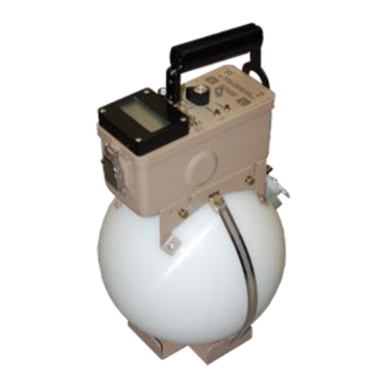
- Page 1 LUDLUM MODEL 2241-4 SURVEY METER WITH NEUTRON DETECTOR October 2022 Serial Number 170658 and Succeeding Serial Numbers...
- Page 2 LUDLUM MODEL 2241-4 SURVEY METER WITH NEUTRON DETECTOR October 2022 Serial Number 170658 and Succeeding Serial Numbers Model 2241-4 with Model 42-31H Detector...
- Page 4 RETURN OF GOODS TO MANUFACTURER If equipment needs to be returned to Ludlum Measurements, Inc. for repair or calibration, please send to the address below. All shipments should include documentation containing return shipping address, customer name, telephone number, description of service requested, and all other necessary information.
-
Page 6: Table Of Contents
Front Panel Calibration Controls Main Board Controls Switch Board Controls Safety Considerations Environmental Conditions for Normal Use Detector Connector Warning Markings and Symbols Maintenance Recalibration Batteries Technical Theory of Operation Main Board Switch Board Display Board Ludlum Measurements, Inc. October 2022... - Page 7 8-11 Detector CC and DTC 8-12 Software License Agreement 8-19 Recycling Parts List Model 2241-4 Survey Meter 10-1 Main Circuit Board, Drawing 408 × 223 10-1 Calibration Board, Drawing 408 × 12 10-3 Display Board, Drawing 408 × 259 10-4 Switch Board, Drawing 408 ×...
-
Page 8: Introduction
Section 1 Section Introduction he Model 2241-4 is a portable microprocessor-based digital Scaler/ Ratemeter coupled to a Model 42-31H Neutron Detector for use in measuring and monitoring neutron radiation. Data is presented on a four-digit (six digits in the scaler mode) Liquid Crystal Display (LCD) with moving decimal point. - Page 9 Model 2241-4 Technical Manual Section 1 All of the features described above may be programmed manually using the internal switch board or by computer through the RS-232 port. Two different detector operating parameters may be stored in non-volatile memory. The switch board can be removed after entering or changing parameters to prevent tampering with setup parameters.
-
Page 10: Getting Started Unpacking And Repacking
Check individual item serial numbers and ensure calibration certificates match. The Model 2241-4 serial number is located on the front panel below the battery compartment. To access the Model 42-31H detector identification, perform the following: (1) loosen the thumbscrews;... -
Page 11: Battery Installation
Using the cable provided, connect the Model 42-31H detector to the Model 2241-4; firmly pushing the connectors together while twisting clockwise until the connector latches (a quarter turn) as illustrated in the diagram to the left. - Page 12 SCALER The display will auto-range to the current level (see figure at left). When auto-ranging down, the Model 2241-4 uses multiples of 5. This technique keeps the decimal point from jumping between numbers when viewing values around multiples of 10.
-
Page 13: Specifications
Model 2241-4 Technical Manual Section 3 Section Specifications : Unit may be used immediately after the LCD Warm-up Time Instrument: initialization sequence is completed (approximately five seconds after power-up). : Readings are within 10% of true value with a detector Linearity connected. -
Page 14: Removable Switchboard Adjustable Parameters
Model 2241-4 Technical Manual Section 3 : Meter readings vary by less than 3% from fully Battery Dependence charged batteries until the battery symbol appears, indicating the need for recharge or replacement. : typically 200 hours with alkaline batteries (display indicates Battery Life low battery condition). -
Page 15: Model 42-31H Neutron Detector
Model 2241-4 Technical Manual Section 3 : set at any point corresponding to the pre- Ratemeter Alert/Alarm selected ratemeter range : adjustable from 1 to 999999 counts Scaler Alarm : adjustable from 1 to 9999 seconds Scaler Count Time Model 42-31H... -
Page 16: Identification Of Controls And Functions Display
Section Identification of Controls and Functions Display The Model 2241-4 utilizes a four-digit liquid crystal display (LCD) with two- digit overflow ( mode) and moving decimal point. The two smaller SCALER digits located in the lower right corner of the display indicate counter... -
Page 17: Front Panel Controls
Model 2241-4 Technical Manual Section 4 mode when the six-digit display (four digits display and two overflow digits in the right corner) reaches 999999 and starts to roll over again. : indicates that the detector is being exposed to radiation OVERLOAD intensities greater than the detector maximum operating limit. -
Page 18: Front Panel Calibration Controls
Switch : pushbutton switch located in the end of the OUNT Model 2241-4 carrying handle, which when depressed, initializes the start of the scaler count accumulation for the preset scaling time. The switch must be in the position to initiate... -
Page 19: Main Board Controls
Note: To access the internal circuit boards, unlatch the latches at each end of the Model 2241-4. Carefully separate the top chassis from the bottom cover (referred to as a can). The can has the audio speaker (unimorph) with a two-conductor cable attached to the main board. -
Page 20: Switch Board Controls
EEPROM, which will retain data even after the Model 2241-4 batteries are removed. After the parameters are entered, the switch board can be removed and the Model 2241-4 will continue to operate from the previously programmed information. -
Page 21: Safety Considerations
The detector operating voltage (HV) is supplied to the detector by way of the input connector. A mild electric shock may occur if contact is made with the center pin of the input connector. Switch the Model 2241-4 to the position before connecting or disconnecting the cable or detector. - Page 22 Verify instrument voltage input rating before connecting to a power converter. If the wrong power converter is used, the instrument and/or power converter could be damaged. The Model 2241-4 Survey Meter is marked with the following symbols: CAUTION, RISK OF ELECTRIC SHOCK (per ISO 3864, No. B.3.6): designates a terminal (connector) that allows connection to a voltage exceeding 1 kV.
-
Page 23: Maintenance
The Model 2241-4 instrument may be externally cleaned with a damp cloth (using only water as the wetting agent). Do not immerse the instrument in any liquid. -
Page 24: Batteries
Model 2241-4 Technical Manual Section 6 Batteries The batteries should be removed and the battery contacts cleaned of any corrosion at least every three months. If the instrument has been exposed to a very dusty or corrosive atmosphere, service the batteries more frequently. - Page 25 Model 2241-4 Technical Manual Section 7 Section Technical Theory of Operation Refer to the Main Detector Input/Amplifier Board schematic for the following: Negative-going detector pulses are coupled from the detector through C021 to amplifier U021. R024 and CR021 protect the input of U021 from inadvertent shorts.
- Page 26 Model 2241-4 Technical Manual Section 7 High Voltage Supply High voltage is developed by blocking oscillator Q241, T141, and C244 and rectified by voltage multiplier CR041-CR043, C041-C043, and C141. High voltage increases as current through R241 increases, with maximum output voltage and Q241 saturated.
- Page 27 S1 (FUNCTION) S1 is a 16-position binary rotary switch, which selects the programmable parameters for the Model 2241-4. The switch selects the parameters using the hexadecimal numbering system via buss lines S2-S4 S2-S4 are pushbutton switches that enter/change the variables for each of the 16 parameters.
-
Page 28: Switch Board
Model 2241-4 Technical Manual Section 8 Section Instrument Setup & Calibration Entering or Changing Switch Board Parameters On the switch board, select the desired parameter to enter or change by using the corresponding switch position. Depress the FUNCTION ENTER button and a character on the LCD will start to flash. The flashing character indicates that the program is in the parameter change mode. -
Page 29: The Function Switch
: A 16-position rotary switch labeled “0-9” and “ FUNCTION Switch .” This switch selects a parameter setup mode for the Model 2241-4. If the board is not installed, the normal operation mode (counting mode) is selected. If the switch board is installed, the selector switch must be set to the 0 position for normal instrument operation. - Page 30 Model 2241-4 in the POSITION 0 NORMAL OPERATION normal (counting) operating mode. Unplugging the switch board from the Model 2241-4 main board defaults to the normal operating mode. (µs) allows changing the detector dead time POSITION 1 DEAD TIME correction for the current detector setup.
- Page 31 (R/hr or Sv/h) by entering the appropriate Calibration Constant (position 2) and Dead Time correction (position 1). The Model 2241-4 will automatically convert to the correct reading when switching between R and Sv. The time base for count C is set independently in position 4.
- Page 32 RESPONSE TIME for the current detector setup. If the response is set to 0, the Model 2241-4 automatically calculates (for variable mode) the time constant based on the incoming cps. If a variable of 1-199 is entered for TC, the response time becomes fixed.
- Page 33 RS-232 port to POSITION D DATA DUMP MODE dump ratemeter data every two seconds. The Model 2241-4 is fully functional during RS-232 data dump with the exception of the audio function. The LCD will alternate between display of the ratemeter and the word “...
- Page 34 : This 9-pin “D” type connector is designed RS-232 PORT CONNECTOR as a DCE port. A straight wire cable (extension cable) connects the Model 2241-4 to a computer’s 9-pin RS-232 port. RS-232 CONNECTOR PIN OUT FUNCTION NC (No Connection)
-
Page 35: Calibration
Model 2241-4 Technical Manual Section 8 Calibration The Model 2241-4 calibration routine consists of entering detector parameters into memory by way of the switch board and adjusting the controls ( ) for the specific detector operating requirements. DISC The first subsection of calibration will give a general overview of detector... - Page 36 Model 2241-4 Technical Manual Section 8 In the special case of GM detectors, a minimum voltage must be applied to establish the Geiger-Mueller characteristic. Further changes in will have little effect on this type of detector. : The output pulse height of the GM detector is not GM Detectors proportional to the energy of the detected radiation.
-
Page 37: Counts Per Minute (C/M) Calibration
Section 8 OUNTS PER MINUTE ALIBRATION This procedure will set up the Model 2241-4 for the Counts/minute (C/m) mode of operation. Refer to Section 8, (Page 8-2 and following) for more information on setup parameter variables. A Ludlum Model 500 Pulser or equivalent is required. If the pulser does not have a high-voltage display, use a high-impedance voltmeter with at least 1000 megohms input resistance to measure the detector high voltage. -
Page 38: R/Hr Calibration
Connect the Model 500 Pulser to detector input and adjust DISC the specific detector operating parameters. Adjust the pulser amplitude to 1.5 times the Model 2241-4 discrimination level. Adjust the pulser output to 800 cpm and confirm that the Model 2241-4 reads 800 cpm ±10% on the ratemeter setting. - Page 39 PC and the Model 2241-4. The program also incorporates the algorithm to calculate the detector CC and DTC. The software is offered in a DOS version (part number 1370-025) or a WINDOWS version (part number 1370-024).
- Page 40 Model 2241-4 Technical Manual Section 8 Refer to Section 8, Subsection “Function Switch Position Descriptions and Variables,” for cps readout variables. Select position 1 on the detector selector switch located on the front panel. Starting with switch position 1, enter the following...
- Page 41 Model 2241-4 Technical Manual Section 8 Reference the table at the end of this section to determine the cps/exposure rate (cps/ER). The conversion can be determined by placing the detector in a radiation field, which produces from 50 to 200 cps. Calculate the count/exposure rate using the equation to the left.
- Page 42 Model 2241-4 Technical Manual Section 8 CC and DTC Algorithm Equations (5) and (6) convert units per time (R/hr Display Units) to units per second: units units time second Insert the cps lo data point (8 mR/hr for the Model 44-9 example)
- Page 43 Model 2241-4 Technical Manual Section 8 As an example, assume a 60-second count sample in a low field of 8 mR/hr: Example 26,427 CORR Place detector in the high field and enter the counts per second: Equation 8 counts SAMPL...
- Page 44 Model 2241-4 Technical Manual Section 8 Enter the results of equations (9) and (10) into equation (11) to solve for Equation 11 count Example seconds 84 x 10 count Solve for f Equation 12 units CORR Example ...
- Page 45 This table represents some of the common detectors operated with the Model 2241-4. Consult the LMI sales department for information concerning detectors not listed in the table above. *The dead time values for these scintillation detectors are due to the dead time of the Model 2241-4 electronics.
- Page 46 Model 2241-4 Technical Manual Section 8 Ludlum Measurements, Inc. Page 8-19 October 2022...
- Page 47 Model 2241-4 Technical Manual Section 8 Ludlum Measurements, Inc. Page 8-20 October 2022...
- Page 48 Model 2241-4 Technical Manual Section 8 Ludlum Measurements, Inc. Page 8-21 October 2022...
-
Page 49: Recycling
To this end, Ludlum Measurements, Inc. strives to supply the consumer of its goods with information regarding reuse and recycling of the many different types of materials used in its products. With many different agencies –... -
Page 50: Parts List
Technical Manual Section 10 Section Parts List Reference Description Part Number Model 2241-4 Survey Meter UNIT Completely Assembled Model 2241-4 Survey Meter 48-2444 Main Circuit Board, BOARD Completely Assembled Drawing 408 × 223 Main Circuit Board 5408-223 CAPACITORS 0.1µF, 50V 04-5663 0.1µF, 50V... - Page 51 Model 2241-4 Technical Manual Section 10 Reference Description Part Number C241 1µF, 35V 04-5656 C242 68µF, 10V 04-5654 C243 0.1µF, 50V 04-5663 C251 68µF, 10V 04-5654 TRANSISTORS Q101 2N7002L 05-5840 Q141 MMBT3904LT1 05-5841 Q211 2N7002L 05-5840 Q212 MMBT4403LT1 05-5842 Q241...
-
Page 52: Calibration Board, Drawing 408
Model 2241-4 Technical Manual Section 10 Reference Description Part Number R023 10K, 1/4W, 1% 12-7839 R024-R025 4.75K, 1/4W, 1% 12-7858 R026 8.25K, 1/8W, 1% 12-7838 R031 1M, 1/4W, 5% 10-7030 R032 1M, 1/4W, 5% 10-7028 R033-R034 1G, FHV-1, 2% 12-7686 R111-R113 22.1K, 1/4W, 1%... - Page 53 Model 2241-4 Technical Manual Section 10 Reference Description Part Number 1M, HV 09-6814 RESISTORS 10K, 1/3W, 1% 12-7748 R5-R6 1M, 1/3W, 1% 12-7751 1K, 1/3W, 1% 12-7750 CONNECTOR CONN-640456-6, MTA100×6 13-8095 Display Board, BOARD Completely Assembled Drawing 408 × 259...
- Page 54 Model 2241-4 Technical Manual Section 10 Reference Description Part Number Switch Board, BOARD Completely Assembled Drawing 408 × 45 Switch Board 5408-052 CAPACITORS C1-C2 4.7µF, 10V 04-5578 C3-C4 10µF, 20V 04-5592 4.7µF, 10V 04-5578 100µF, 10V 04-5576 INTEGRATED MAX220EPE 06-6359...
- Page 55 Model 2241-4 Technical Manual Section 10 Reference Description Part Number Series "C" -UG706/U 13-7751 JACK-09-9011-1-419 18-9080 HANDLE PIN 7408-055 SWITCHES 30-1-PB GRAYHILL 08-6517 S3-S4 7101-SYZ-QE C&K 08-6511 30-1-PB GRAYHILL 08-6517 PA-600-210 08-6501 MPS-103F 08-6699 SWTCH CAP, BLK C-22 08-6698 BATTERY B1-B2 "D"...
-
Page 56: Display Board, Drawing 408 × 259
Model 2241-4 Technical Manual Section 11 Section Drawings Main Circuit Board, Drawings 408 × 223 (3 sheets) Main Circuit Board Component Layout, Drawing 408 × 224 (2 sheets) Calibration Board, Drawing 408 × 12 Calibration Board Component Layout, Drawing 408 × 13 (2 sheets) Display Board, Drawing 408 ×... -
Page 71: Rs-232 Output Formats
The RS-232 port is configured at 9600 baud, 8 data bits, no parity, and 1 stop bit (9600,8,N,1). Ludlum Measurements can supply a Windows-based software that can be used to help calibrate the instruments, but note that it will not communicate with the newer ASCII output Model 2241-2 units. - Page 72 Model 2241-4 Technical Manual Appendix A RS-232 Commands E – auto dump off A – auto dump on C – start scaler F – set scaler count time R – send parameters from instrument to computer S – read parameters from computer to instrument O –...
- Page 73 Model 2241-4 Technical Manual Appendix A BYTE34 CheckSource+3 BYTE35 CheckSource+4 BYTE36 PercentCS+0 BYTE37 MinDisplay+0 BYTE38 Carriage Return (0DH) BYTE39 Line Feed (0AH) Input of “S” Command – Send Parameters BYTE1 DeadCosntant+0 BYTE2 DeadConstant+1 BYTE3 CalConstant+0 BYTE4 CalConstant+1 BYTE5 CalConstant+2 BYTE6...
-
Page 74: Ascii Output Format
Model 2241-4 Technical Manual Appendix A Input of “F” Command – Set Count Time BYTE1 CountTime+0 BYTE2 CountTime+1 Units 0 = R 1 = Sv 2 = cpm Timebase 0 = min 1 = seconds AudioDivide 0 = Auto 1 = Manual... - Page 75 Model 2241-4 Technical Manual Appendix A byte 8 Line Feed (0AH) The ratemeter is displayed as 5 ASCII digits with a decimal, if necessary, and matches the LCD display on the 2241-2. The display mode is a value from 0 to 9 representing the display units.
Need help?
Do you have a question about the 2241-4 and is the answer not in the manual?
Questions and answers