
Related Manuals for Ludlum Measurements 2241-3


Summary of Contents for Ludlum Measurements 2241-3
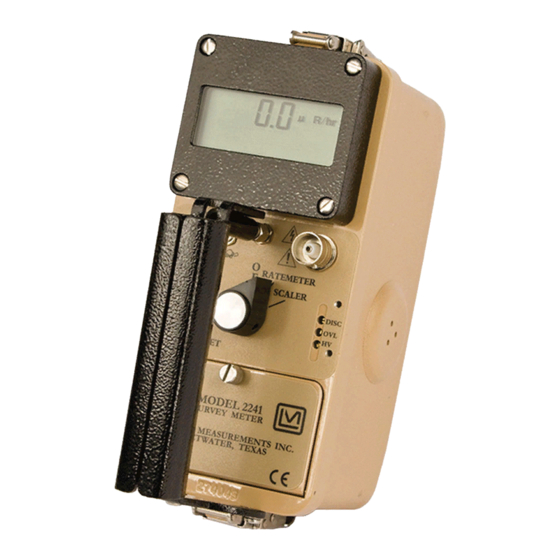
- Page 1 LUDLUM MODEL 2241-3 & 2241-3i SURVEY METER January 2016 Serial Number 299171 and Succeeding Serial Numbers...
- Page 2 LUDLUM MODEL 2241-3 & 2241-3i SURVEY METER January 2016 Serial Number 299171 and Succeeding Serial Numbers...
-
Page 3: Statement Of Warranty
RETURN OF GOODS TO MANUFACTURER If equipment needs to be returned to Ludlum Measurements, Inc. for repair or calibration, please send to the address below. All shipments should include documentation containing return shipping address, customer name, telephone number, description of service requested, and all other necessary information. -
Page 6: Table Of Contents
Front Panel Calibration Controls Main Board Controls Switch Board Controls Safety Considerations Environmental Conditions for Normal Use Detector Connector Warning Markings and Symbols Maintenance Operational Check Recalibration Batteries Technical Principle of Operation Main Board Switch Board Display Board Ludlum Measurements, Inc. January 2016... - Page 7 Model 2241-3 & 3i Technical Manual Instrument Setup & Calibration Entering or Changing Switch Board Parameters Loading Default Parameters The Function Switch Function Switch Position Descriptions and Variables Calibration General Detector Setup Information Counts per minute (C/m) Calibration R/hr Calibration...
-
Page 8: Introduction
Section 1 Section Introduction he Model 2241-3 is a portable microprocessor-based digital Scaler/ Ratemeter designed for use with scintillation, Geiger-Mueller (GM), and proportional-type detectors for measurement of ionizing radiation. Data is presented on a four-digit (six digits in the scaler mode) Liquid Crystal Display (LCD) with moving decimal point. - Page 9 The Model 2241-3i is identical to the Model 2241-3 except for the following: The five-position selector switch located on the front panel has been modified to provide for selection of an internal detector.
-
Page 10: Getting Started
Check individual item serial numbers and ensure calibration certificates match. The Model 2241-3 serial number is located on the front panel below the battery compartment. Most Ludlum Measurements, Inc. detectors have a label on the base or body of the detector for model and serial number identification. -
Page 11: Connecting A Detector
Connect a detector to the Model 2241-3 by using the cable provided; firmly pushing the connectors together while twisting clockwise until the connector latches (1/4 turn). The diagram to the left illustrates how this is done. Next, place the detector selector switch in the appropriate position. - Page 12 Section 2 The display will auto-range to the current level (see figure at left). When auto-ranging down, the Model 2241-3 uses multiples of 5. This technique keeps the decimal point from jumping between numbers when viewing values around multiples of 10.
- Page 13 (for fixed response mode) and three times slower when in variable response mode. The slow response position is normally used when the Model 2241-3 is displaying low numbers, which require a more stable display. The fast response position is used at high count levels.
-
Page 14: Specifications
Model 2241-3 & 3i Technical Manual Section 3 Section Specifications Linearity : Readings are within 10% of true value with a detector connected. Display : a four-digit Liquid Crystal Display (LCD) with digits 1.3 cm (0.5 in.) in height. Two additional 0.5 cm (0.2 in.) high digits are used for the overflow counter ( mode) and exponential powers (parameter setup). -
Page 15: Removable Switchboard Adjustable Parameters
Model 2241-3 & 3i Technical Manual Section 3 Note: button only silences the alarm in the current mode RESET that the instrument is in. For example, the button will RESET not affect the scaler alarm if the instrument is in the ratemeter mode. - Page 16 Model 2241-3 & 3i Technical Manual Section 3 : enables or disables dump mode to the RS-232 RS-232 Data Dump Mode port (˝D˝ type connector). When enabled, the data will be dumped every two seconds. RS-232 Detector Setup Mode : allows for input of detector parameters via...
-
Page 17: Internal Detector Specifications For Model 2241-3I
Model 2241-3 & 3i Technical Manual Section 3 Internal Detector Specifications for Model 2241-3i: Operating Voltage : recommended 550 volts Input Sensitivity : -30 mV ±10 mV Dead Time : typically 80 microseconds Energy Reponse: within ±15% Tube: 30 mg/cm... -
Page 18: Identification Of Controls And Functions
Section Identification of Controls and Functions Display The Model 2241-3 utilizes a four-digit liquid crystal display (LCD) with a two-digit overflow ( mode) and moving decimal point. The two SCALER smaller digits located in the lower right corner of the display indicate... -
Page 19: Front Panel Controls
Model 2241-3 & 3i Technical Manual Section 4 : indicates that the batteries have decreased to the Low Battery icon minimum operating voltage of 2.2 ±0.1 Vdc. Instrument will continue to operate for approximately 24 hours thereafter. COUNTING : indicates that the scaler... -
Page 20: Front Panel Calibration Controls
RESET alarm and/or alert condition. The scaler alarm can only be reset by depressing the scaler count switch located in the end of the Model 2241-3 handle. Note: button only silences the alarm in the current mode RESET that the instrument is in. -
Page 21: Main Board Controls
Note: To access the internal circuit boards, unlatch the latches at each end of the Model 2241-3. Carefully separate the top chassis from the bottom cover (referred to as a can). The can has the audio speaker (unimorph) with a two-conductor cable attached to the main board. -
Page 22: Switch Board Controls
EEPROM, which will retain data even after the Model 2241-3 batteries are removed. After the parameters are entered, the switch board can be removed and the Model 2241-3 will continue to operate from the previously programmed information. Changing parameters and information on switchboard controls are covered in detail in Section 8 of this manual. -
Page 23: Safety Considerations
) is supplied to the detector by way of the input connector. A mild electric shock may occur if contact is made with the center pin of the input connector. Switch the Model 2241-3 to the position before connecting or disconnecting the cable or detector. - Page 24 Verify instrument voltage input rating before connecting to a power converter. If the wrong power converter is used, the instrument and/or power converter could be damaged. The Model 2241-3 Survey Meter is marked with the following symbols: CAUTION, RISK OF ELECTRIC SHOCK (per ISO 3864, No. B.3.6): designates a terminal (connector) that allows connection to a voltage exceeding 1 kV.
-
Page 25: Maintenance
Maintenance Instrument maintenance consists of keeping the instrument clean and periodically checking the batteries and the calibration. The Model 2241-3 may be externally cleaned with a damp cloth (using only water as the wetting agent). Do not immerse the instrument in any liquid. Observe the following precautions when cleaning: 1. -
Page 26: Batteries
Model 2241-3 & 3i Technical Manual Section 6 Ludlum Measurements offers a full-service repair and calibration department. We not only repair and calibrate our own instruments, but most other manufacturers’ instruments as well. See Section 8 “Instrument Setup & Calibration,” for further details on instrument calibration. -
Page 27: Technical Principle Of Operation
Model 2241-3 & 3i Technical Manual Section 7 Section Technical Principle of Operation Refer to the Main Detector Input/Amplifier Board schematic for the following: Negative-going detector pulses are coupled from the detector through C021 to amplifier U021. R024 and CR021 protect the input of U021 from inadvertent shorts. - Page 28 Refer to the Switch Board schematic for the following: S1 is a 16-position binary rotary switch, which selects the programmable parameters for the Model 2241-3. The switch selects the parameters using the hexadecimal numbering system via buss lines Ludlum Measurements, Inc. Page 7-2...
-
Page 29: Display Board
Model 2241-3 & 3i Technical Manual Section 7 S2-S4 S2-S4 are pushbutton switches which enter/change the variables for each of the 16 parameters. U1 is a +5 V powered RS-232 driver/receiver used to interface the Model 2241-3 to a computer. -
Page 30: Instrument Setup & Calibration
Model 2241-3 & 3i Technical Manual Section 8 Section Instrument Setup & Calibration Entering or Changing Switch Board Parameters On the switch board, select the desired parameter to enter or change by using the corresponding switch position. Depress the FUNCTION ENTER button, and a character on the LCD will start to flash. -
Page 31: The Function Switch
.” FUNCTION Switch This switch selects a parameter setup mode for the Model 2241-3. If the board is not installed, the normal operation mode (counting mode) is selected. If the switch board is installed, the selector switch must be set to the 0 position for normal instrument operation. - Page 32 Model 2241-3 & 3i Technical Manual Section 8 (µs) allows changing the detector dead time POSITION 1 DEAD TIME correction for the current detector setup. Setting this parameter to “0” disables dead time correction. The dead time adjusts from 0 to 9999 microseconds (µs).
- Page 33 POSITION 3 DISPLAY UNITS detector setup number. The Model 2241-3 and detector may be calibrated in either exposure rate (R/hr or Sv/h) by entering the appropriate Calibration Constant (position 2) and Dead Time correction (position 1). The Model 2241-3 will automatically convert to the correct reading when switching between R and Sv.
- Page 34 POSITION 6 RESPONSE TIME the current detector setup. If the response is set to 0, the Model 2241-3 automatically calculates (for variable mode) the time constant based on the incoming cps. If a variable of 1-199 is entered for TC, the response time becomes fixed.
- Page 35 POSITION D DATA DUMP MODE ratemeter data every two seconds. The Model 2241-3 is fully functional during RS-232 data dump with the exception of the audio function. The LCD will alternate between display of the ratemeter and the word “...
-
Page 36: Calibration
1370-024). Read the Software License Agreement at the end of this section before installing any LMI software. Calibration The Model 2241-3 calibration routine consists of entering detector parameters into memory by way of the switch board and adjusting the controls ( ) for the specific detector operating requirements. -
Page 37: General Detector Setup Information
Section 8 instrument checkout procedure and the variables are saved under detector setup number “1” when shipped from Ludlum Measurements, Inc. The following subsection deals with exposure rate calibration. The detector Calibration Constant (CC) and Dead Time Correction (DTC) are the two primary parameters used in the exposure rate calibrations (R/hr and Sv/h). -
Page 38: Counts Per Minute (C/M) Calibration
OUNTS PER MINUTE ALIBRATION This procedure will set up the Model 2241-3 for the Counts/minute (C/m) mode of operation. Refer to Section 8, (Page 8-2 and following) for more information on setup parameter variables. A Ludlum Model 500 Pulser or equivalent is required. If the pulser does not have a high-voltage display, use a high-impedance voltmeter with at least 1000 megohms input resistance to measure the detector high voltage. - Page 39 Model 2241-3 & 3i Technical Manual Section 8 Switch the switch to the position. Select RATE RATE position 1 on the detector selector switch located on the front panel. Select switch positions 1-6 and adjust for the FUNCTION following parameters: Switch Pos.
-
Page 40: R/Hr Calibration
Model 2241-3 & 3i Technical Manual Section 8 Adjust the pulser amplitude to 1.5 times the Model 2241-3 discrimination level. Adjust the pulser output to 800 cpm and confirm that the Model 2241-3 reads 800 cpm ±10% on the ratemeter setting. -
Page 41: Determining Cc And Dtc
PC and the Model 2241-3. The program also incorporates the algorithm to calculate the detector CC and DTC. The software is offered in a DOS version (part number 1370-025) or a WINDOWS version (part number 1370-024). - Page 42 Model 2241-3 & 3i Technical Manual Section 8 Preliminary CPS Setup Refer to Section 8, Subsection “Function Switch Position Descriptions and Variables,” for cps readout variables. Select position 1 on the detector selector switch located on the front panel. Starting with...
- Page 43 Model 2241-3 & 3i Technical Manual Section 8 Reference the table at the end of this section to determine the cps/exposure rate (cps/ER). The conversion can be determined by placing the detector in a radiation field, which produces from 50 to 200 cps.
- Page 44 Model 2241-3 & 3i Technical Manual Section 8 CC and DTC Algorithm Equations (5) and (6) convert units per time (R/hr Display Units) to units per second: units units time second Insert the cps lo data point (8 mR/hr for the Model 44-9 example)
- Page 45 Model 2241-3 & 3i Technical Manual Section 8 As an example, assume a 60-second count sample in a low field of 8 mR/hr: Example 26,427 CORR Place detector in the high field and enter the counts per second: Equation 8...
- Page 46 Model 2241-3 & 3i Technical Manual Section 8 Enter the results of equations (9) and (10) into equation (11) to solve for Equation 11 count Example seconds 84 x 10 count Solve for f Equation 12 units...
- Page 47 This table represents some of the common detectors operated with the Model 2241-3. Consult the LMI sales department for information concerning detectors not listed in the table above. *The dead time values for these scintillation detectors are due to the dead time of the Model 2241-3 electronics.
- Page 48 Model 2241-3 & 3i Technical Manual Section 8 Ludlum Measurements, Inc. Page 8-19 January 2016...
- Page 49 Model 2241-3 & 3i Technical Manual Section 8 Ludlum Measurements, Inc. Page 8-20 January 2016...
- Page 50 Model 2241-3 & 3i Technical Manual Section 8 Ludlum Measurements, Inc. Page 8-21 January 2016...
-
Page 51: Recycling
To this end, Ludlum Measurements, Inc. strives to supply the consumer of its goods with information regarding reuse and recycling of the many different types of materials used in its products. With many different agencies –... -
Page 52: Parts List
Model 2241-3 & 3i Technical Manual Section 10 Section Parts List Reference Description Part Number Model 2241-3 UNIT Completely Assembled Survey Meter Model 2241-3 Survey Meter 48-2864 BOARD Completely Assembled Main Circuit Board, Main Circuit Board 5408-285 Drawing 408 × 285 CAPACITORS 0.1µF, 50V... - Page 53 Model 2241-3 & 3i Technical Manual Section 10 Reference Description Part Number C241 1µF, 35V 04-5656 C242 68µF, 10V 04-5654 C243 0.1µF, 50V 04-5663 C251 68µF, 10V 04-5654 TRANSISTORS Q101 2N7002L 05-5840 Q141 MMBT3904LT1 05-5841 Q211 2N7002L 05-5840 Q212 MMBT4403LT1...
-
Page 54: Calibration Board, Drawing 408
Model 2241-3 & 3i Technical Manual Section 10 Reference Description Part Number R026 8.25K, 1/8W, 1% 12-7838 R031 4.75M, 1/4W, 5% 10-7030 R032 1M, 1/4W, 5% 10-7028 R033-R034 1G, FHV-1, 2% 12-7686 R111-R113 22.1K, 1/4W, 1% 12-7843 R121 100Ohm, 1/4W, 1%... -
Page 55: Display Board, Drawing 408 × 259
Model 2241-3 & 3i Technical Manual Section 10 Reference Description Part Number RESISTORS R110 1M, 1/3W 12-7751 R111 10K, 1/3W 12-7748 R112 1M, 1/3W 12-7751 R113 1K, 1/3W 12-7750 R114 1M, 1/3W 12-7751 R120 1M, 1/3W 12-7751 CONNECTOR CONN-640456-7, MTA100... -
Page 56: Switch Board, Drawing 408
Model 2241-3 & 3i Technical Manual Section 10 Reference Description Part Number Switch Board, BOARD Completely Assembled Drawing 408 × 45 Switch Board 5408-052 CAPACITORS C1-C2 4.7µF, 10V 04-5578 C3-C4 10µF, 20V 04-5592 4.7µF, 10V 04-5578 100µF, 10V 04-5576 INTEGRATED... - Page 57 Model 2241-3 & 3i Technical Manual Section 10 Reference Description Part Number AUDIO UNIMORPH 21-9251 BATTERY B1-B2 ˝D˝ Duracell Battery 21-9313 MISCELLANEOUS Model 2241 Switch Board Add On 4408-053 Model 2241 Digital Bezel Assembly 4408-051 Portable Battery Contact Set 2001-042...
- Page 58 Model 2241-3 & 3i Technical Manual Section 11 Section Drawings Main Circuit Board, Drawings 408 × 285 (3 sheets) Main Circuit Board Component Layout, Drawing 408 × 286A Calibration Board, Drawing 408 × 98 Calibration Board Component Layout, Drawings 408 × 99 (2 sheets) Display Board, Drawing 408 ×...
-
Page 73: Rs-232 Output Formats
The RS-232 port is configured at 9600 baud, 8 data bits, no parity, and 1 stop bit (9600,8,N,1). Ludlum Measurements can supply a Windows-based software that can be used to help calibrate the instruments, but note that it will not communicate with the newer ASCII output Model 2241-2 units. - Page 74 Model 2241-3 & 3i Technical Manual Appendix A RS-232 Commands E – auto dump off A – auto dump on C – start scaler F – set scaler count time R – send parameters from instrument to computer S – read parameters from computer to instrument O –...
- Page 75 Model 2241-3 & 3i Technical Manual Appendix A BYTE34 CheckSource+3 BYTE35 CheckSource+4 BYTE36 PercentCS+0 BYTE37 MinDisplay+0 BYTE38 Carriage Return (0DH) BYTE39 Line Feed (0AH) Input of “S” Command – Send Parameters BYTE1 DeadCosntant+0 BYTE2 DeadConstant+1 BYTE3 CalConstant+0 BYTE4 CalConstant+1 BYTE5...
-
Page 76: Ascii Output Format
Model 2241-3 & 3i Technical Manual Appendix A Input of “F” Command – Set Count Time BYTE1 CountTime+0 BYTE2 CountTime+1 Units 0 = R 1 = Sv 2 = cpm Timebase 0 = min 1 = seconds AudioDivide 0 = Auto... - Page 77 Model 2241-3 & 3i Technical Manual Appendix A byte 8 Line Feed (0AH) The ratemeter is displayed as 5 ASCII digits with a decimal, if necessary, and matches the LCD display on the 2241-2. The display mode is a value from 0 to 9 representing the display units.
Need help?
Do you have a question about the 2241-3 and is the answer not in the manual?
Questions and answers