Table of Contents
Advertisement
Quick Links
Advertisement
Table of Contents

Summary of Contents for semaphore TBOX LT2-530 Series
- Page 1 User's Guide Cabling & Technical Specifications Version 1.09...
- Page 2 Canada Division 2 Disclaimer Every effort has been made to ensure the accuracy of the information in this guide. However, Semaphore assumes no responsibility for the accuracy of the information. Product information is subject to change without notice. Windows 2003, XP, VISTA, 2008, 7, 8, 10 are trademark of Microsoft Corp.
- Page 3 Important Safety Instructions Read and understand all instructions. Save these instructions. Read the instruction manual carefully before using the equipment and comply with the instructions that it contains to avoid mistakes and to prevent any personal injury or damage to property. ...
- Page 4 Environmental Considerations Battery Disposal ! CAUTION: There is a danger of a new battery exploding if it is incorrectly installed. Replace the battery only with the same or equivalent type recommended by the manufacturer. Do not dispose of the battery along with household waste. Contact your local waste disposal agency for the address of the nearest battery deposit site.
-
Page 5: Table Of Contents
ABLE OF ONTENTS ...................... 11 RESENTATION How to use this manual?.................... 14 1.1. What is in the manual? ....................14 1.2. What is not in the manual? ..................14 The Hardware Models....................15 2.1. LT2-530-x ........................15 2.2. LT2-532-x ........................15 2.3. - Page 6 7.5. Info properties ......................45 7.6. Advanced ........................45 7.6.1. Start/Stop ........................45 7.6.2. Alarms ..........................47 7.6.3. Sampling Tables ......................50 7.6.4. Temperature ........................50 7.6.5. ModBus Transactions ..................... 51 7.6.6. Ports ..........................51 7.6.7. TCP/IP ..........................52 7.6.8. Environment variables ....................
- Page 7 10.5. POP3 Server ......................92 10.5.1. Alarm Acknowledgment through POP3................93 10.6. NTP Server ....................... 94 10.6.1. Time accuracy ......................... 94 10.7. DynDNS ........................95 10.7.1. How to configure DynDNS in TBox ................. 95 10.8. Virtual Server ......................97 10.9. IP Bridge ........................
- Page 8 13.5. ReadSMS status ..................... 129 13.6. Get Message in Text Tag ..................130 Datalogging ......................131 14.1. Introduction ......................131 14.2. The chronologies ....................133 14.2.1. Digital chronologies ...................... 133 14.2.2. Analog chronologies ..................... 133 14.3. The sampling tables ....................134 ModBus Transactions ...................
- Page 9 20.1. Power Supply ......................166 20.2. RS232 (standard) ....................166 20.3. RS232 (optional) ....................167 20.4. RS485 ........................168 20.5. Ethernet ......................... 169 20.6. Digital Inputs - Counter inputs ................170 20.7. Digital Outputs ...................... 171 20.8. Analog Inputs – Current/Voltage ................172 20.9.
- Page 10 Version : 1.09...
-
Page 11: Presentation
Version : 1.09... - Page 12 The ‘all-in-one’ concept of WEB SERVER Control and Monitoring using PC, Smart phone, tablet, … IP INTERFACE ALARMS SMTP, HTTP, FTP, … Router, Gateway, SMS, e-mail, FTP, Firewall, SSL, … Pictures, … COMMUNICATION DATALOGGING Chronologies (SoE) Ethernet, GSM, RS485 … Sampling Tables ModBus, SNMP, …...
- Page 13 Overview of possibilities Consulting Programming process locally or through HTML remotely Sending of Alarms Communication to a remote site Retrieving data and consulting the process remotely Retrieving data locally Version : 1.09...
-
Page 14: How To Use This Manual
1. How to use this manual? 1.1. What is in the manual? This manual constitutes the essential of documentation. It first introduces to the hardware concept Different models of chapter 2 Quick overview on installing and powering chapter 3 Then it brings you to the programming of using TWinSoft. -
Page 15: The Hardware Models
2. The Hardware Models is a All-in-one RTU, including a fix number of I/Os and of communication ports. It is not possible to add local I/O or communication ports but a connection to ‘Remote device’ is always possible. is available in different models, offering several combinations of I/O and different communication ports: 2.1. -
Page 16: Lt2-542-X
2.4. LT2-542-x Communication ports 16 x DI/O On all models of LT2-532 Each channel can be used as input or output RS232 3 first DI can be used as fast counter (>10 Khz) RS485 Ethernet 6 x AI (0..10V and 4..20mA) Individual selection of signal per channel -x Options With validity bit working with 4..20mA signal... -
Page 17: Hardware
Version : 1.09... -
Page 18: Installation Of The Tbox-Lt2
3. Installation of the TBox-LT2 3.1. Installation of the Rack on a DIN rail is mounted on a mini rack equipped with one spring for DIN rail fixing. To fix it on a DIN rail: 1. Make sure the is with its upper side on top 2. -
Page 19: Cabling
3.4. Cabling is equipped with compact spring-cage terminal blocks. This connector allows a high density of connections. Press the orange plastic with a screwdriver for inserting and removing the cable. Connection capacity Without ferrule Solid cable: 0.2 .. 1.5 mm² (24..16 AWG) With ferrule without plastic sleeve Solid or Stranded cable: 0.2 .. - Page 20 Version : 1.09...
-
Page 21: Tw In Soft - Getting Started
Version : 1.09... -
Page 22: Installation Of Twinsoft
4. Installation of TWinSoft 4.1. System requirements Hardware: PC running Windows. 32bits or 64 bits Memory: 32 MB minimum. Hard Disk: 350 MB required plus the application files. Display: VGA, SVGA with a minimum resolution of 1024 x 768. Mouse: any Windows compatible mouse. -
Page 23: Installation Of The Cd-Rom
4.2. Installation of the CD-ROM From the USB stick of TWinSoft Suite, when running the Setup, the following software’s are available TWinSoft 11.xx TWinSoft is a Suite of software required for developing an application for any model of TBox RTU. The basis for configuring TBox RTU application is explained in this manual. - Page 24 WebForm Viewer This setup contains the “ActiveX” used with legacy HTML page used to display dynamic objects dedicated to TBox. It must be installed on the PC used by operators using IE to display legacy HTML pages. In such case, TWinSoft Suite is not required; only the ActiveX needs to be installed. With you will preferably use WebForms 2.0.
-
Page 25: Programs Of 'Twinsoft Suite
4.3. Programs of ‘TWinSoft Suite’ During installation of TWinSoft, a group of programs is created where TWinSoft can be started from. Other programs and menus (Found on Semaphore folder): Accessories: group containing the utility ‘Password generator’ and ‘Reset User preferences’: reset of registry information to restore the default configuration of TWinSoft. -
Page 26: Starting Twinsoft
5. Starting TWinSoft I am the Wizard of TWinSoft! When you start TWinSoft the first time, or when you create a new document, I help you with some basic configurations. The use of TWinSoft is free, but sending of a program to is protected. -
Page 27: Wizard
5.1. Wizard The “New Document Wizard” helps you getting started with a new application by gathering information about your hardware and some basic configuration. Except for the “Type of RTU”, settings can be modified latter from the “RTU properties”. Free name of the RTU Station address (1..254) Sub address (0..255) I/O combination... -
Page 28: Communicating With Tb Ox Lt2
5.2. Communicating with TB Once you have opened a document, either created a new one with the Wizard or opened an existing one, you can establish the connection with your The possible communications are serial, Ethernet, USB or modem, according to the media used to connect . -
Page 29: Communication Possibilities Of Twinsoft
5.3.1. Communication possibilities of TWinSoft Offline: this option avoid sampling Local: you select a serial port of the PC (typically RS232). The Baudrate must fit with the port of you are connected to. LT2. TCP/IP: to establish a communication in TCP/IP, typically through the Ethernet port of TWinSoft will establish a connection with the IP address specified in the ‘Ethernet’... - Page 30 In IPv4 properties, type IP setting in the same subnet as TBox: Example of subnet: 172.25.110.xxx 255.255.255.0 In case you intend to change IP address of , you can define several IP addresses in Windows. In IPv4 properties, click “Advanced...”, then “Add...” to add an IP address in the subnet corresponding to the current IP address of TBox, or to the one you want to change Version : 1.09...
-
Page 31: Ip Setting Of Twinsoft
5.3.3. IP setting of TWinSoft You may encounter three different situations requiring specific IP setting. 1. You program your through Ethernet and you want to keep its IP address. You select in the drop list of IP addresses the one corresponding to the you are connected 2. -
Page 32: Factory Ip Address - Changing Ip Address
3. You don’t program your through a direct Ethernet connection and you don’t want TWinSoft to adapt to the Ethernet IP address Example: you access your through ADSL or GPRS. You check the option “Don’t change IP address after sending…” and you type the current IP address of the port of RTU you are connected to, for instance the GPRS IP address. -
Page 33: Testing Communication
5.5. Testing communication Once you have selected the media on the PC, you can test the communication. From the main menu of TWinSoft: Communication RTU identification: Available information: Name of the RTU Type of Hardware Version of Operating System Status of the process ModBus address of the Station Sub-address of the Station... -
Page 34: Reset Of Tbox Lt2
5.6. Reset of TBox LT2 Pushing toggle switch to “Reset” position restarts the program: stack of alarms and events are erased datalogging is maintained Tags with initial value are set to their initial value; others are maintained ... -
Page 35: Sending 'Operating System
5.7. Sending ‘Operating System’ Operating System is the heart of your It contains all features of In some cases you might have to change this operating system, when new features are available or a bug fix released. From the main menu, “Communication”, select “Send to TBox”. -
Page 36: Saving And Sending A Program
5.9. Saving and Sending a Program Like any Windows program, TWinSoft creates “Documents”. A document corresponds to a application. Each of them must be saved using the Windows standard. 5.9.1. Saving a document – Backup document Possibilities for saving a document: ... -
Page 37: Sending An Application
Test of memory Detail on memory “used” and “free” is also available during compilation. See details chapter 20.1: Technical Specifications. 5.9.3. Sending an application In order to have running with the program you have developed with TWinSoft, you have to send it. - Page 38 Version : 1.09...
-
Page 39: Tw In Soft - Programming
Version : 1.09... -
Page 40: Introduction
6. Introduction TWinSoft uses the standard look and feel of “Windows Explorer”, with at the left side a list of folders and at the right side the content of the folder selected. Each Folder consists in a list of items. For instance the list of “Tags”, or in the ‘Alarms’... -
Page 41: Rtu Properties
7. RTU properties Setting the properties of has never been so easy thanks to a set of comprehensive dialog boxes, available from the main tool bar. RTU properties can be accessed easily by clicking this icon. The RTU properties are divided into: ... -
Page 42: General Properties
7.1. General properties RTU Type: The type of RTU you have selected with the Wizard. It cannot be changed! Name: type a free name for . It will be displayed when doing a ‘RTU identification’ and used by the data aggregator software, TView. Maximum 11 characters. -
Page 43: Add-Ons
Sub address: if more than 254 x must be installed in one project, you need to define a Sub address. As this is not ModBus standard, it is only supported by ‘TComm.dll’ based software (TWinSoft, TView,… please call your distributor for further information). -
Page 44: Ip Security
7.4. IP Security 7.4.1. Firewall embeds a Firewall. Once activated it gives access to exception rules in folder "Resources" "IP Security" "Firewall" (see chapter 11.2). Once Firewall has been activated, make sure to define rules! In case you activate Firewall without declaring any rules, all IP access to will be blocked. -
Page 45: Ssh
7.4.3. SSH SSH stands for "Secure Shell". It is a secured protocol you can use to access TBox in Console mode. SSH requires a login. As of OS 1.35, SSH login name can be changed in . You cannot use the name "root", which has highest privileges and a full system access. - Page 46 START Reset all physical outputs: when active, at start-up the RTU reinitializes the outputs to ‘0’. After that the outputs are monitored according to the process. When not active, at start-up the outputs are maintained to their last status. After that, outputs are monitored according to the process (default).
-
Page 47: Alarms
Disconnect ModBus address at program stop: all variables will have their ModBus address disconnected, which means that external equipment accessing the RTU will receive communication error. This feature has been implemented to allow a SCADA detecting immediately a TBox is stopped: as the ModBus addresses are not available, the RTU stays in communication but returns an 'Exception' error. - Page 48 The object ‘Alarms’ used in a WebForm displays the Event stack. It corresponds also to the list of Alarms sent to TView. Alarm stack: is an internal stack used to buffer alarms when there are several to handle at the same time or when the communication port is not available or when retries are required.
- Page 49 Alarm filter on both transitions: this option allows computing the filter of alarm condition during both transitions: when the Tag value goes to alarm condition AND when it leaves alarm condition. This option will be applied to all alarm conditions. This is particularly useful to filter interferences on inputs.
-
Page 50: Sampling Tables
such case, you declare a filter of some seconds on the alarm condition and check this option; the alarm on the sensor will be inhibited properly in case of power failure. 7.6.3. Sampling Tables This menu gives access to the parameters for long period recording in Sampling tables. (See chapter 14.3: ‘Sampling tables’) These configurations concern all sampling... -
Page 51: Modbus Transactions
7.6.5. ModBus Transactions Reset the device Trigger only if success When communicating as ‘Master’ using ‘ModBus Transactions’, a Trigger is switching communication to the remote device (see chapter 15. ModBus Transactions). This Trigger activates the communication according to a ‘State’ or ‘Edge’. Working with ‘Edge’, the RTU restores automatically the Tag after the transaction(s). -
Page 52: Tcp/Ip
HTTP(S): port used to access as WebServer. (by default= 80 & 443) ModBus/TCP-Slave: port used by a ‘Master’ to access as ‘Slave’. (by default=502) Changing of TCP port is automatically applied to 'WebForms 1.0' as it uses ModBus for data communication. -
Page 53: Environment Variables
TCP/IP miscellaneous To access these features you have to enable advanced IP configuration (see chapter 17.1.7) See also the sequence of configuration Appendix F. Gives access to TCP/IP redirection: IP Forwarding Virtual Server (configurable in IP Parameters as described chapter 12.8) Once checking one of the above features, a login corresponding to the code typed when enabling advanced IP configuration is required. -
Page 54: Power Fail
7.6.9. Power Fail Working with an external 12 V backup battery, the RTU informs you when the main voltage is out of order and the RTU is powered from the 12 V backup battery. An internal DI variable informs that the main power broke down. -
Page 55: Plug&Go
Accepted parameters are: %station%: name of the RTU %email%: e-mail of the RTU %time%: complete date & time %condition%: ! (if alarm active) %YY%: year in 2 digits %YYYY%: year in 4 digits %M%: month in 1 digit (if possible) %MM%: month in 2 digits %MONTH%: month in letters... -
Page 56: Resources
8. Resources The resources represent the list of the hardware that your has to its disposal. being an all-in-one RTU has a fixed hardware all built within one module: A Power Supply A CPU Communication ports Groups of I/O ... -
Page 57: Communication Ports Tabs
8.2.1. Communication ports tabs According to the type of communication port (RS232. RS485, modem or Ethernet), different tabs are available: Parameters: general parameters (local or modem, Baudrate, Protocol). DCV: Digital Communication Variables. Special variables with a pre-defined function (communication error, modem online, …). (see chapter 8.3) ACV: Analog Communication Variables. -
Page 58: Ethernet
8.2.3. Ethernet Obtain IP address: is connected to a DHCP server providing its IP settings. Use IP address: IP address the IP address of the Ethernet of (given by the network administrator). Subnet mask the subnet mask defined by the subnet the will be included in (given by the network administrator). - Page 59 GSM-data (CSD) settings Initialization: should not be changed PIN Code: If the SIM card you have inserted uses a PIN code, type it at the place of the letter n. Example: with the PIN code 4896, you should have in the field: AT+CPIN=“4896” including the quotes If the SIM card you have does not require a PIN code, you can leave the field as it is or erase it completely.
- Page 60 IP Communication (GPRS/EDGE/3G/HSDPA) settings The GSM 3G supports third generation communication standard, including, from slowest to fastest: GPRS (2G), EDGE (2.5G), UMTS (3G) and HSPDA (3.5G). There is no configuration to select one or the other network; the GSM 3G will select the fastest available. You have to choose either ‘GSM-Data’...
- Page 61 Communication Variables dedicated to GPRS, 3G,… IP Communication Some communication variables allow manual handling of GPRS and give information on the status. Digital Communication Variable COMx.GPRSCon Handles the GPRS/3G connection. Working in manual connection, writing ‘1’ forces a connection; writing ‘0’ forces a disconnection.
- Page 62 Sending of SMS with GSM configured in GPRS/3G While connected in GPRS and a SMS has to be sent through the classical SMS-Center, will automatically disconnect, send the SMS and reconnect. GPRS IP settings GPRS represents a TCP/IP connection using GSM network. It then requires a TCP/IP configuration. Obtain address automatically:...
-
Page 63: Usb
8.2.5. USB is equipped with 1 x USB port. It can be used as "Device" as well as "Host". Equipment supported: PC USB Memory Stick USB as Device When the USB port runs as "Device", it waits for a "Host", like a PC. can be connected to a PC to be programmed by TWinSoft. -
Page 64: Communication Variables
8.3. Communication Variables Communication variables are dedicated registers providing different status of the communication. It is very useful for monitoring and controlling the connection. Those variables are divided into 2 tabs, Digital Communication Variables (DCV) and Analog Communication Variable (ACV). When you need one, double click it from the list and click <OK>! It becomes a Tag and then available in any feature of 8.3.1. - Page 65 Name Description COMx.NoDial Modem: with PSTN modem, reading ‘1’ indicates that no dial tone has been detected when the modem has picked-up the line. (not available with Must be RESET by the user. COMx.GPRSCon GPRS/3G: Writing 1: demand of connection. (Automatic when selecting “Connection at start-up”) USE A TRIGGER INPUT CONTACT TO ACCESS THE VARIABLE COMx.ModBusResp...
- Page 66 Example: when a user is connected you can modify its level access by writing a value in the register COMx.level (level available: 0, 1, 2 or 3). Those values can be stored in analog chronology for keeping a history on the access.
-
Page 67: Groups Of I/Os
Name Description COMx.ByteCount GSM/3G: returns all bytes (sent and received) during a IP communication. It is reset at each start/stop of the program, then to sum the bytes up you should use the following BASIC code: 8.4. Groups of I/Os The Hardware is represented in TWinSoft with a hierarchy of 3 levels: ... -
Page 68: System Variables
8.5. System variables The system variables have pre-defined functions. They are very useful to check or to act on features of They are divided into ‘Digital’ and ‘Analog’. 8.5.1. Digital System Variables According to its function a register is Read/Write or Read only. In the following table, the column R/W indicates: : Read only. - Page 69 Index Name Description PrgEnb Program Enable: when reset to ‘0’, allows stopping the execution of BASIC/Ladder program. It can be useful to execute the program manually (see next). PrgOnc Program Once: when set to ‘1’, executes the cycle of BASIC/Ladder program once.
-
Page 70: Analog System Variables
Index Name Description DisAla3 Alarm: flag #3 that can be associated to any Alarm condition. When at value ‘1’, inhibits the sending of alarm. DisAla4 Alarm: flag #4 that can be associated to any Alarm condition. When at value ‘1’, inhibits the sending of alarm. - Page 71 Index Name Description UtcTim Time: Universal Coordinated Time (UTC). It is the number of seconds since 01/01/1970, GMT time. It is used as time-stamp reference for datalogging. ZonBia Time: Time difference in seconds with GMT. ZonID Time: ID of the zone where has been installed.
- Page 72 Index Name Description GpsSpeed GPS: with a GPS connected to TBox, current speed of TBox, expressed in km/h GpsRoute GPS: with a GPS connected to TBox, current direction of TBox, expressed in degree (0 .. 359.9 degree) AlaPop3 Alarm: it indicates the number of alarm needing to be acknowledged by POP3 connection EvenCur Alarm: it indicates the current Event ID...
- Page 73 Index Name Description XmlTag Backup allows backup/restore of Tags. Writing 1 in the variable forces the backup of value of Tags into the SD card. When the operation has succeeded, the Tag returns automatically to zero (see also return codes below). A file tags.xml is created in directory ../public/xml of the SD card with the value of internal variables Writing 2 in the variable forces the restore of the value of Tags saved in file...
-
Page 74: Timers & Counters
- FTP: bit 24 - NTP: bit 25 - PRINTER: bit 26 - PLUG AND GO: bit 27 - POP: bit 28 - SFTP: bit 29 - USB: bit 30 - VPN: bit 31 Example: there is a lot of Modbus transactions that fill the log and you wish to debug the GPRS or 3G connection. -
Page 75: Tags & Variables
9. Tags & Variables A Tag is essential for any programming An alarm is conditioned from a Tag. The Datalogging mechanism records values of Tags. BASIC/Ladder logic executes a process by handling Tags. … Any variable of the that you want to use in any configuration has to be available as a Tag. -
Page 76: Physical I/O
9.1. Physical I/O The physical I/O’s are the signals available on I/O cards. They can be easily accessed from the ‘Resources’ (see chapter 8: ‘The Resources’). Details about the different I/O are available chapter 20. To create a Tag of a variable from the Resources: ... -
Page 77: Analog I/O
Examples of Physical Inputs: Digital Input Analog Input 9.1.1. Analog I/O Concerning Analog I/O, some settings are available: Type: depending on the model of there may have different types of signal available (1..5V; 4..20mA; 0..10V, ...) By default, Analog Inputs are configured as 0..10V inputs, to prevent damaging the hardware if it is cabled before it is programmed. -
Page 78: Internal Variables (Registers)
9.2. Internal Variables (Registers) An internal variable (also known as Register) is an addressable location of the memory. It is used as flag, as temporary value, to make a calculation, … There are 3 types of internal variables: Digital (DIV) Boolean register with possible values: 0 or 1. -
Page 79: Analog Internal Variable
The initial value is the value the Tag will have at the start-up of If you select ‘None’ the value is maintained at start-up. ModBus Address is discussed in chapter 9.3. 9.2.2. Analog Internal Variable To create an Analog Internal Variable (also known as Register), from the list of Tags, click ‘Add a Tag’. Select ‘Analog’... -
Page 80: Text Internal Variable
For each Analog Register, the formats available are: 8 bits (Signed or Unsigned) 16 bits (Signed or Unsigned) 32 bits (Signed or Unsigned) Float (32 bits, IEEE 754) By default, TWinSoft creates Analog Internal Variable in format ‘Float’. Check whether it fits with the use you intend to have of the variable. -
Page 81: Modbus Address
9.3. ModBus address The ModBus address is the link to the outside world. When equipment must sample Tags in it uses its ModBus addresses; like TView, SCADA or TWinSoft. Each Tag has a unique ModBus address. By default TWinSoft proposes a ModBus address. You can change it if you want. -
Page 82: Tags - Presentation / Write
9.4. Tags - Presentation / Write This tab contains configuration used when the Tag is declared in a Report or in a WebForm. The Description is also used in TView. Presentation settings can also be used when the value of the Tag is included into message (SMS or e- mail). -
Page 83: Run Time Parameters
9.5. Run Time Parameters Run time parameters feature allows accessing some configurations through Tags, in order to modify them "on line". For instance, to change a tel. number of a SMS recipient, the e-mail address of a recipient, the address of SMTP server, the handling of alarm condition, …... -
Page 84: Datalogging Parameters
Alarm Recipient Parameter Recipient Type Tag Format Phone Number ModBus, SMS, Printer, RAS, Custom Text (20) E-mail To Email Text (120) E-mail Cc Email Text (120) Alarm Time Slices Alarm Holidays Parameter Tag Format Parameter Tag Format From Hour Byte Byte From Min Byte... -
Page 85: Gsm/Gprs Parameters
DynDNS Parameter Tag Format Parameter Tag Format Server Text (120) Text (120) Authentication Bool User Name Text (30) Password Text (30) HTTP Parameter Tag Format (max.) Server Text(120) TCP Port Word Authentication Bool Login Text(30) Password Text(30) 9.5.5. GSM/GPRS Parameters GPRS Authentication Parameter Tag Format (max. -
Page 86: Rtu Properties
BASIC: 9.5.6. RTU Properties Parameter Tag Format (max. length) StationName Text (11) POP3AckTimeout Word SMSTimeout Word HTTPServerPort Word FTPServerPort Word ModbusOverTCPPort Word ModbusOverUDPPort Word HTTPServerPort Word ModBusTCPSlavePort Word ModBusAddress Byte Version : 1.09... -
Page 87: Ip Parameters
10. IP Parameters IP parameters consist in the global configuration for TCP/IP services: connecting to an ISP (dial-up connection) sending files: FTP(S), SFTP sending e-mail: SMTP(S) reading e-mail subject: POP3 time synchronization: NTP DynDNS: handling of public, dynamic IP addresses ... -
Page 88: Isp Configuration
10.1. ISP configuration ISP stands for Internet Service Provider. An ISP represents the entrance to Internet. It is required to access Internet with a dial-up connection: PSTN, GSM-DATA (CSD). It represents the connection to the company you call to access an Internet service, like sending e-mail or files (FTP). -
Page 89: Ftp(S) Server
10.2. FTP(S) Server FTP stands for File Transfer Protocol. When subscribing an account to an ISP, usually you have some Mbytes to your disposal for sending files. It supports secure, encrypted communication. The FTP server represents the target when sending files. The directory where the files are sent is defined in the Recipient (see chapter 12.4). -
Page 90: Sftp Server
10.3. SFTP Server SFTP provides secure in transferring files, using SSH protocol. It is also called Secure File Transfer Protocol. The SFTP server represents the target when sending files. The directory where the files are sent is defined in the Recipient (see chapter 12.4). The sending is generated through an alarm recipient “SFTP”. -
Page 91: Smtp(S) Server
10.4. SMTP(S) Server SMTP stands for Simple Mail Transfer Protocol. It is usually the main reason for subscribing an account to an ISP, for sending e-mail. It supports secure, encrypted communication Concerning e-mail, is able to send e-mail (through SMTP server) and to read e- mail (through POP3 server) The SMTP Server represents the mail server used for sending e-mail (typically the one of the ISP where we have subscribed and account). -
Page 92: About Smtp Redundancy
10.4.1. About SMTP Redundancy If you create more than one SMTP Server, they can be used in redundancy according to their order in the list. You decide to work with redundancy when creating the e-mail recipient (see chapter 12.4). 10.5. POP3 Server POP3 stands for Post Office Protocol 3. -
Page 93: Alarm Acknowledgment Through Pop3
10.5.1. Alarm Acknowledgment through POP3 Introduction With sending a SMS through a GSM, it is possible to acknowledge the alarm by sending back a SMS to In some countries, SMS can only be sent through email. A POP3 connection can then be used to acknowledge the alarm. -
Page 94: Ntp Server
Supplementary information 1. The time between phases 1 and 4 can be determined in RTU properties --> Advanced Alarms properties 2. System Analog Variable: #40 [AlaPop3] indicates the quantity of alarms needing to be acknowledged by POP3 connection and #43 [Pop3State] indicates the state of connection. 3. -
Page 95: Dyndns
10.7. DynDNS DynDNS stands for Dynamic Domain Name System. It is a service, provided by companies like www.DynDNS.org or www.noip.com, offering the handling of dynamic IP addresses. When working with GPRS connection, using public dynamic IP addresses, it is not possible to access the RTU directly, as you don't know its IP address. - Page 96 2. Create in TWinSoft IP Parameters the connection to DynDNS: Name Type any name Server DynDNS Server to which will connect when it detects a changing in its IP address. It should not be changed. Path Location in the server of the table of correspondences between IP address -->...
-
Page 97: Virtual Server
10.8. Virtual Server To access Virtual Server configuration, you have to activate “RTU properties” -> “Protection” -> “Enable Advanced IP Configuration” (see chapter 17.1.5) and “RTU properties” -> “Advanced” -> “TCP/IP”, check Virtual Server (see chapter 7.6.6) Virtual Server Parameters allow defining specific routes (in <--> out) based on IP protocol and TCP port Virtual Server Parameters example: Accessing a Camera with IP address 192.168.1.100 connected to Ethernet, through a 3G connection using TCP port=81... -
Page 98: Ip Bridge
10.9. IP Bridge 10.9.1. Introduction What is a Bridge ? A Bridge is a device that connects two or more networks as a seamless single network. It supports any protocol as it operates on MAC-layer addresses, and then protocol independent. The bridge passes packets according to the destination and its internal table of addresses. -
Page 99: Example With Ms-Cpu32X
In IP ports you want to bridge, select the bridge you have configured as above. The IP of the bridge will be applied to each port. Example with MS-CPU32X 10.9.3. Example with MS-CPU32X. In example below, one wants to access remote camera connected to TBox Ethernet. By default in TBox, each IP port in TBox is separated from each other. -
Page 100: Sending Configuration Through A Bridge
10.9.4. Sending Configuration through a Bridge With example above, imagine TWinSoft is connected to COM3 of CPU#1 (192.168.1.11) and you wish to update the application of CPU#4. In menu “PC setup”: Uncheck “Always use IP address of the RTU” Type the IP address of destination TBox (192.168.1.51 in this case) Check “Don't change IP address after sending program”... -
Page 101: Trace Log
10.11. Trace Log The Trace Log feature is a powerful tool to debug the , like modem connection or TCP/IP connection. , it can be accessed from the menu 'Communication' When you are online with your 'Retrieve from TBox' 'Trace Log'. Many events, related to many tasks are stored in the log. -
Page 102: Ip Security
11. IP Security IP security services are: VPN Firewall (must be activated from the RTU properties -> IP security) 11.1. VPN 11.1.1. Introduction This feature provides secure connections using OpenVPN. OpenVPN version used: 2.3.0-1. can be configured as "Client" or "Server" in mode routing. Any physical media can be used (Ethernet, 3G). - Page 103 Name: Type a name, without SPACE. This name will be the reference to your VPN entry, like in the list of communication ports to protect, or as default prefix to the communication variables, ... Type: Select what will be: "Server" or "Client". Note that other parties need to support OpenVPN.
- Page 104 Certificates and keys can be created using OpenSSL.exe. CA Certificate: The certificate signed from a Certification Authority. It is used to check the authenticity of the partner certificate. Working in an internal network, you have to create your own self-signed CA. After having generated certificates using OpenSSL, copy the content of CA.crt here...
-
Page 105: Firewall
11.2. Firewall To access Firewall rules, make sure you have activated Firewall from the “RTU properties” -> “IP security” (see chapter 7.4) Two kinds of rules can be applied: Input: to prevent incoming access Forward: to prevent access when TBox configured in IP forwarding 11.2.1. - Page 106 Protocol: If you have selected "Custom" as service (see above): Any: all protocols (UDP, TCP, ICMP) have access to TBox. You can filter access based on TCP port and/or source IP (see below). UDP, TCP, ICMP: you select the protocol yourself. PING protocol is supported by .
-
Page 107: Firewall "Forward
11.2.2. Firewall “Forward” When Firewall has been activated from the RTU properties, IP forwarding, NAT and Virtual Servers rules are blocked. By defining forward rules, you will control data communication between ports. A rule defines an exception: the control of interconnection between ports is based on: ... - Page 108 PING protocol is supported by . It works on ICMP protocol for which there is no TCP port Port: When selecting a "Custom" service, you can type a TCP port. When selecting a specific service, the TCP port is automatically set as defined in "RTU properties"...
-
Page 109: Alarms
12. Alarms 12.1. Introduction Alarm module of is the gate to the outside world. An alarm consists in a communication event, not only for sending warning messages but to establish a connection, like we will see. Via alarms, you are able to send SMS message to Mobile phone, send e-mail, send files to a FTP site, to dial another or a SCADA, …... -
Page 110: Digital Alarm Condition
12.2. Digital Alarm Condition Tagname: The Tag selected to generate the alarm. Type: The edge on which the alarm is going to be started (rising, falling or both). Message or Report: text or file associated to the alarm. Depending on the type of recipient associated, you can send a message or a report. It can be a message sent to a GSM, a message or report sent as e-mail, to a printer or the file sent by FTP …... - Page 111 Filter: The time in hour:minute:second during which the condition must stay TRUE, before the call is generated. Filter can be tested either during both transitions or only during the transition selected (see chapter 7.5.2) Handling: The handling option allows blocking each alarm condition, manually or automatically. ...
-
Page 112: Analog Alarm Condition
12.3. Analog Alarm Condition Tagname: The Tag selected to generate the alarm. Type: Maximum or Minimum. The threshold for which the alarm will be started. If the value of the analog Tag passes under (minimum) or over (maximum) this threshold, the alarm is started. If an alarm must be generated for both a maximum and a minimum threshold, 2 conditions must be declared with the same Tag. - Page 113 Call all Recipients: To be used when selecting a Group of Recipients. When the option is cleared: calls the first one in the group. In case the alarm cannot be acknowledged after the number of tries, automatically calls the next recipient in the group and so on until it succeeds. Then it stops.
-
Page 114: Recipients
12.4. Recipients To access the definition of Recipients, click the folder ‘Alarms’ in the Project workspace and select ‘Recipients’. The types of recipients supported are: Internal: the alarm is saved in the stack of events and no call is generated. It can be used to memorize a particular event without generating an alarm or to test an alarm condition. - Page 115 Pager/SMS:to send SMS to a mobile or message to a Pager. Select the Service corresponding to the SIM card in TBox and a Modem. Type the Phone Number of the Pager or Mobile. The default Dial prefix is ATDT. It should not be changed unless the modem needs...
- Page 116 FTP: is able to send files to a FTP Host (see chapter 10.2. FTP Server). In the recipient configuration you only need to indicate the directory where you want to send the files. SFTP: is able to send files to a through Secure FTP (see chapter 10.3. SFTP Server). In the recipient configuration you only need to indicate the directory where you want to send the files.
-
Page 117: Group Of Recipients
12.5. Group of Recipients A group of recipients is composed of several recipients, which can be of different types (SMS, e-mail, …). You can declare several groups. Then previous to creating groups of recipients, you have to create first the recipients (see above). You can then associate an Alarm condition to a ‘recipient’... -
Page 118: Sms Coding
12.6.1. SMS coding By default, SMs message are coded according to GSM 03.38 table (7 bits character). It provides a total length of message of 160 characters: Δ space ¡ ¿ £ Φ “ ¥ Γ è Λ ¤ é Ω... -
Page 119: Alarm Timetables
With a Digital Tag for which you have defined ‘States’ in the ‘Presentation’ menu, those states will be used; otherwise, 0 and 1. With a Float Tag for which you have defined a number of decimals in the ‘Presentation’ menu, this number will be used; otherwise, fixed to 3 decimals. 12.7. -
Page 120: Timetables
12.7.3. Timetables Based on the ‘Time Slices’, days of the week and ‘Holidays’ you create different ‘Timetables’ according to activity periods in your company (day shift, night shift, holidays, week-end, …). A time table can then be associated to a recipient. You select for each day of the week which time slice will be part of the timetable (Holidays being treated like a unique ‘day’). -
Page 121: Alarms Table
12.8. Alarms Table The Alarms table of TWinSoft displays the Event stack of . The Events stack is the visible part of the handling of some system events and alarms in .The internal queue of alarms is not accessible. You access the Alarms table from the main menu: Communication Retrieve from TBox Alarms: Date/Time of the Message Acknowledg. -
Page 122: Readsms/Pop3 Embedded
13. ReadSMS/POP3 embedded 13.1. Introduction ReadSMS/POP3 is the ability to to receive and interpret incoming SMS messages, and to read “subject” field of e-mail in order to execute tasks. Receiving an SMS requires a GSM on ReadSMS/POP3 features allow two uses: 1. -
Page 123: Acknowledgment Of An Alarm By Sending Data To The Rtu
13.2. Acknowledgment of an alarm by sending data to the RTU Two types of recipient may require an acknowledgment by SMS: Pager/SMS: sending a message through a SMS-C (standard way) E-mail: sending a message through a SMTP server, which can be forwarded as SMS through a dedicated service Alarm conditions associated to a recipient of... -
Page 124: Message Sent By Tbox
The incoming SMS must arrive within this time-out for the alarm to be acknowledged. If not, a retry will be executed according to the definition in the Recipient. After the end of retries, the alarm will be considered as in error: “auto-ack” and the system variable ‘AlaErr=1’. Working with ‘Group of Recipients’: - with option ‘Call all recipients’: all recipients have to acknowledge the alarm. -
Page 125: Controlling The Rtu Using Sms Message Or Pop3
13.3. Controlling the RTU using SMS message or POP3 ReadSMS/POP3 provides the possibility to control the RTU by sending a SMS to or by reading e-mail using POP3 service. A message can combine several data: Password, acknowledgment ID, writing values directly to ModBus addresses,... -
Page 126: Writing Tag With Direct Addressing ( W )
13.3.2. Writing Tag with Direct addressing ( W ) You write a value or a text directly to a ModBus address. Syntax: #Wmodbus address=value# #Wmodbus address=”text”# Examples: #W20480=123# This message sent to the RTU will write value 123 to the analog Tag with ModBus address 20480 #W1500=”jean@tbox.be”# This message sent to the RTU will the text “jean@tbox.be”... -
Page 127: Access Protection ( P )
13.3.5. Access Protection ( P ) ReadSMS/POP3 access protection is independent from the GSM port it is associated to. In other words, even if the communication port is protected, ReadSMS feature will not specially be protected. ReadSMS/POP3 has its own independent access protection configuration, that can be activated from:... -
Page 128: Set A Digital Tag ( S )
13.3.7. SET a digital Tag ( S ) You write 1 to a digital Tag using its ModBus address. Syntax: #Smodbus address# Example: #S32# The digital Tag at ModBus address 32 will be set to 1. Note: ReadSMS checks access protection level of the port before writing (see chapter 13.3.5. above) 13.3.8. -
Page 129: Automatic Update Of A Recipient's Tel. Number
13.4. Automatic Update of a Recipient’s tel. number An existing recipient of type ‘Pager/SMS’ can be updated with the mobile number of the originator. The idea is to check the incoming message, for instance using ReadSMS status (see next) and to send back a message to the originator. -
Page 130: Get Message In Text Tag
13.6. Get Message in Text Tag This feature allows receiving the complete message (SMS or POP3) into a TEXT Tag. At the exception of the caller ID, which is available is a dedicated Communication Variable. The message will then be parsed using BASIC functions. When this feature is active, ReadSMS/POP3 pre-defined message feature (see chapter 13.3.1) is not available anymore. -
Page 131: Datalogging
14. Datalogging 14.1. Introduction Datalogging allows memorizing values of your process, in order to visualize its history. contains memory for recording historical values of Tags and events (see technical specifications); the latter is what we call the database of There are two categories of databases: The Chronologies hronologies are 'On event' recordings, by means of changes in Tags (also known as “Sequence of Events”). - Page 132 The Sampling Tables. Sampling tables use ‘Periodical’ recording, with a minimum period of 1 second. Recording in sampling tables happens at fixed intervals and does not depend on signal variations; it uses the clock of the CPU to determine the recording. Date and time of only the last record is stored.
-
Page 133: The Chronologies
14.2. The chronologies 14.2.1. Digital chronologies Example of an entry in Digital chronology: Recording the starting and stopping of ‘VALVE1’. Edges: Recording on positive and (or) negative edge. Handling: Enabled: always recorded. Disabled: never recorded. PowerF: recording disabled in case of ‘mains’ power failure. ... -
Page 134: The Sampling Tables
14.3. The sampling tables Type: records data internaly on a minimum time-base of 1 second. After the period selected (see next) the selected type of data (min., max., ..)is recorded. This value can be: - Minimum : minimum value during the period. - Maximum : maximum value during the period. - Page 135 In case you wish to make recording every day, or even with a longer period, the options are: daily: recording once a day weekly: recording once a week monthly: recording once per month. The hour of the day, the day of the week and/or the month are defined once for all sampling tables in the RTU Advanced properties (see chapter 7.6.3) Size: The size can be expressed on two ways:...
-
Page 136: Modbus Transactions
15. ModBus Transactions Introduction ModBus Transactions feature allow exchanging data between two or more ModBus stations via any communication ports. One often speaks of 'Master Network' because it is a ModBus Master communication: the Master ) executes reading and writing in slave(s) through any media (RS485, Ethernet, modem...). The protocol will be ModBus-RTU or ModBus/TCP according to the media used. -
Page 137: Creating A Modbus Transaction
Trigger: Select a digital Tag that will trigger the communication, according to a ‘Condition’ (see next). Working with several equipment, you declare different Tags and then control differently the communication to each equipment. The Trigger must be a digital variable (DIV). Condition: Condition of Tag ‘Trigger’... - Page 138 External Source. All the following parameters concern the Slave station: Device: select an existing external device from the ‘Resources’. You can create one clicking the button Type: select the type of the external variable. The choices are: With external source ‘ModBus device’ (any LT,, any ModBus device) Types Connection in remote device...
-
Page 139: Modbus Transactions Through Modem
15.3. ModBus Transactions through modem With a remote device accessed by a dial-up modem, the connection must be first established using an Alarm “ModBus”. The sequence is the following: Create a Remote Device, associated to the communication port of the modem and to a Trigger – DIV (digital register) always active. -
Page 140: Periodic Events
16. Periodic Events When tasks have to be executed periodically, periodical events constitute an easy way of creating events to launch the tasks, like ModBus Transactions, sending of test alarm, datalogging, a piece of Ladder/BASIC logic, etc..., and this, independently from any other condition. A periodic event could be compared to an automatic timer. - Page 141 Example of a ‘daily event’: The Tag ‘Half_Hour’ (a DIV) will be automatically SET each 30 minutes, at each xx:15:00 and xx:45:00. The task(s) associated to Tag ‘Half_Hour’ will be executed each 30 minutes, for instance a communication to a Remote Device, the Tag would be the Trigger of the Remote Device. Examples of a ‘weekly event’: Sending a SMS each Wednesday at 12:00 AM Sending a daily report at 6:00 AM...
-
Page 142: Protection (Access Security)
17. Protection (Access security) This (optional) access control on prevents non-authorized persons from accessing the RTU and from opening the TWinSoft document. Several protocols can be protected: ModBus, HTTP, FTP (server), ReadSMS. More protection can be implemented, like Firewall (chapter 11.2), OpenVPN (chapter 11.1) or IEE802-1X though an add-on (see chapter 7.2. - Page 143 TWinSoft presents all the communication ports according to your hardware configuration: From the RTU properties tab ‘Protection’, you activate the general access security feature. Global code: type in the 4 character hexadecimal code that you have used to generate the Access Codes with the utility Password Generator (see chapter 17.3 following).
-
Page 144: Monitoring Access Level
User list: You add users with for each an access level. 17.1.2. Monitoring Access Level Current access level on serial and modem ports can be checked using the Communication Variables (see chapter 8.3.2). 17.1.3. ReadSMS protection ReadSMS feature allows controlling TBox using SMS or e-mail. It can be protected as explained chapter 13.3.5. -
Page 145: Http Protection
17.1.4. HTTP Protection HTTP protection assures protection at HTTP level, to prevent accessing files stored in using HTTP protocol. Typically when displaying HTM files with a browser. Once HTTP security is activated, each file building the web site must be assigned an access level. In folder "Web and Reports files", right click each file: ALL files (.twa, .htm, .twf, .gif, ...) composing a view must be given an access level: ... -
Page 146: Modbus Tcp Protection On Socket
Protection on Objects Inside Webform 2.0 Each object composing a webform can be assigned “visibility” and “write” levels of authorization Example with WebForm 2.0 Ease of use recommendations 1. Common files Files that everybody can see and files part of the template (icon, images, ...) should be assigned an access level= 0. -
Page 147: Ftp Protection
17.1.6. FTP Protection can act as a “FTP Server”. It opens access to the micro SD and files sent using alarm recipient “micro SD”. By default, FTP server is accessed in "anonymous" mode. To protect access by a login, check this option. The login is created as explained chapter 17.3 below. -
Page 148: Password Utility
17.3. Password utility The utility program Password generates access codes based on global codes When installing TWinSoft Suite a password-creation program named Password Generator is installed in the same directory as TWinSoft. It can be started from the 'Start' button of Windows and is located in the group of programs “Techno Trade”... -
Page 149: Login/Logout
Two codes have been created: The PASSWORD: this PASSWORD must be used together with the NAME when logging in. The USER ID: this number is available in an Analog Communication Variable when a user is connected to a protected communication port of 17.4. -
Page 150: With Browser
17.4.2. With Browser If you have developed HTML pages based on webforms 2.0, you can access using a broser. acts as a Web Server. Any browser on multiple platforms can access webform 2.0 pages in The utility software TConnect is the perfect candidate to establish this kind of connection (see http://helpdesk.servelec-technologies.com). -
Page 151: Technical Specifications - Cabling
Version : 1.09... -
Page 152: Front Panels
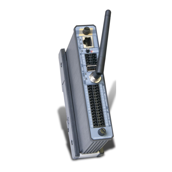
18. Front panels References: LT2-530 18.1. LT2-530-xx LT2-530-3 LT2-530-S Communication (standard) Ethernet RS232 RS485 Communication (optional) -3: GSM modem (3G) -S: Full RS232 port 16 x Digital Input/Output 3 x Fast Digital Inputs ... -
Page 153: Lt2-532-Xx
References: LT2-532 18.2. LT2-532-xx LT2-532-3 LT2-532-S Communication (standard) Ethernet RS232 RS485 Communication (optional) -3: GSM modem (3G) -S: Full RS232 port 16 x Digital Input/Output 3 x Fast Digital Inputs ... -
Page 154: Lt2-540-Xx
References: LT2-540 18.3. LT2-540-xx LT2-540-3 LT2-540-S Communication (standard) Ethernet RS232 RS485 Communication (optional) -3: GSM modem (3G) -S: Full RS232 port 16 x Digital Input/Output 3 x Fast Digital Inputs ... -
Page 155: Lt2-542-Xx
References: LT2-542 18.4. LT2-542-xx LT2-542-3 LT2-542-S Communication (standard) Ethernet RS232 RS485 Communication (optional) -3: GSM modem (3G) -S: Full RS232 port 16 x Digital Input/Output 3 x Fast Digital Inputs ... -
Page 156: Technical Specifications
19. Technical specifications 19.1. Common to all models General Processor 32 bits, ARM based, 400 Mhz Clock Realtime Clock Clock Drift Typical: 1.7 s / day @ 25°C Watchdog Watchdog circuitry included Maximum process cycle time = 1 sec. Toggle Switch STOP - RUN - RESET (see chapter 5.6) Green 2 Hz Normal operation... - Page 157 Protection Power Supply (Vin) Reverse polarity protection FUSE external 12 V battery Soldered Fuse of 3 A. Not replaceable by user. Memory Flash 32 MB (Uboot, LINUX, OS, Application, Web & Reports, Sources) SDRAM 64 MB (Running part of LINUX, OS, Application) SRAM 1 MB, backed up with Lithium battery (datalogging, log, backup value of Tags) MicroSD (optional)
-
Page 158: Lithium Battery Implementation
19.2. Lithium Battery Implementation is equipped with a Lithium battery (3 V). This battery is used to maintain the clock and datalogging when the RTU is out of power (neither Vin not V bat). The time the battery has been used can be checked from the analog system variable “BatUsage”. It returns the number of second the has been out of power and the Lithium battery has delivered current to the SRAM. -
Page 159: Micro Sd Card Implementation
19.3. Micro SD Card Implementation The micro SD card is an option of that provides several features: 1. To store all files running the , including LINUX kernel, Operating System, application, Web and reports, ... This feature is called “Plug&Go” (See Appendix C). 2. -
Page 160: Gsm-3G (Optional)
19.5. GSM-3G (optional) At the front side: Indicates the modem in ‘On line’ (= connected in DATA or GPRS) Transmit or Received = ON Modem GSM-3G Frequencies Model “Europe” WCDMA 900/1900/2100 & GSM850, EGSM900, DCS1800, PCS1900 WCDMA 850/1900/2100 & GSM850, EGSM900, DCS1800, PCS1900 Model “US”... -
Page 161: Antennas
19.5.2. Antennas There are five models of antenna, all 5 bands (850/900/1800/1900/2100 Mhz): 1. The magnetic car antenna - (ref: ACC-GSM-CARANT) 2. The right angle antenna - (ref: ACC-GSM-ANTANGLE). It should be used for demo purpose only because it may interfere with analog measurement. 3. -
Page 162: Antenna Surge Arrestor
19.5.3. Antenna Surge Arrestor Connection to the arrestor: 1) Use the N-M>>N-M connector from the arrestor to connect it to the antenna (remove N- M>>FME-M from antenna if mounted). Connect N-M>>FME-M adapter supplied with the antenna to the arrestor. Connect the antenna cable. 19.6. -
Page 163: I/O
19.7. I/O Group 1 – Internal I/O Power Failure Digital Input returning a failure of Power at Vin, when is equipped with an external 12V Backup battery. Power Supply Voltage Voltage at Vin connection AI: External 12 V Backup Bat. V. Voltage at Vbat connection Internal Temperature Temperature inside the... - Page 164 Group 3 - Digital Outputs V+ MUST BE POWERED 11 30 VDC External voltage to V+ accepted Output Type Current Sourcing Voltage per output Maximum: 30 VDC (depending on V+) Current for 16 outputs at a time Maximum: 3.2 A, protected by a fuse (SMD) Current per output Maximum: 625 mA up to 60°C (with a total for all output of 3.2 A) Maximum: 200 mA between 60°C ..
- Page 165 Group 4 - Analog Inputs Group 7 - Validity 4..20mA Resolution 16 bits Mode Unipolar Model Passive input: sensor must be powered by an ext. power supply Precision 0.1% full scale @ 25°C 0.2% full scale over the temperature range Typical: 249 ...
-
Page 166: Cabling
20. Cabling 20.1. Power Supply Connector: Spring Cage Terminal block (see chapter 3.4) PS & RS Connector +8.. +30 VDC 0 VDC Backup Battery A power supply of minimum 20 VDC is required to charge the external 12 V backup battery. When the voltage at Vin disappears, the 12 V backup battery powers down to 10 V. -
Page 167: Rs232 (Optional)
20.3. RS232 (optional) Description: Connector: Pinout: communication RS232 RJ 45 1. RI white/orange 2. DCD orange 3. DTR white/green 4. Gnd blue 5. RxD (input) white/blue 6. TxD (output) green 7. CTS (input) white/brown 8. RTS (output) brown Exemple of CAT cabling Cabling RJ 45 DB-9... -
Page 168: Rs485
20.4. RS485 Connector: Spring Cage Terminal block (see Appendix H) PS & RS Connector Example: Cabling MS16 About RS485 cabling: Use a twisted pair for signal A and B. RS 485 is not isolated. If cabling equipment in different buildings (different Earth), you have to use ACC-RS485 (ask your local distributor) Maximum length depends on quality of cable, speed and quantity of stations (max. -
Page 169: Ethernet
20.5. Ethernet Description: Connector: Pin out: Ethernet communication RJ 45 not used not used not used not used One can use straight or cross-over cable. It must be a Shielded SFPT cable. It connects to a hub, a switch, a router or directly to a PC. Version : 1.09... -
Page 170: Digital Inputs - Counter Inputs
20.6. Digital Inputs - Counter inputs Connector: Spring Cage Terminal block (see Appendix H) DIO Connector +8 .. +30 VDC DO NOT MANIPULATE CONNECTORS UNDER VOLTAGE. V+ MUST be connected to prevent permanent damage. Cabling to NPN transistor Cabling to PNP transistor (or OPTO) + VDC + VDC R: 1 k (12 VDC) -
Page 171: Digital Outputs
20.7. Digital Outputs Connector: Spring Cage Terminal block (see Appendix H) DIO Connector Load Load Load Load Load Load Load Load Load Load Load Load Load Load Load Load +11 .. +30 VDC Version : 1.09... -
Page 172: Analog Inputs - Current/Voltage
20.8. Analog Inputs – Current/Voltage Connector: Spring Cage Terminal block (see Appendix H) Analog Input Connector Analog Input Pinout In 7 (+) In 6 (+) In 5 (+) In 4 (+) In 2 (+) In 3 (+) In 1 (+) In 0 (+) Inputs (-) Inputs (-) -
Page 173: Analog Inputs - Temperature (Pt 1000)
Pin out - ‘Current’ inputs Models Quantity of AI Input index (see front panel) LT2-530-x 8 inputs: each input 4..20mA or 0..10V Inputs 0, 1, 2, 3, 4, 5, 6, 7 LT2-532-x 8 inputs: each input 4..20mA or 0..10V Inputs 0, 1, 2, 3, 4, 5, 6, 7 LT2-540-x 6 inputs: each input 4..20mA or 0..10V... -
Page 174: Analog Outputs - Current
20.10. Analog outputs – Current Connector: Spring Cage Terminal block (see Appendix H) Analog Output Connector Analog Outputs Pinout Out 1 (+) Out 0 (+) Cabling to an actuator feedback Out x Actuator Version : 1.09... -
Page 175: Appendixes
Version : 1.09... -
Page 176: Appendix A. Licenses
Appendix A. Licenses TWinSoft software itself is not protected and can be installed freely on any PC to develop TWinSoft document (online or offline) and to monitor The only operation protected is the sending of an application to In order to find the best way for you we offer different possibilities: A.1. -
Page 177: Appendix B. Time In Rtu
Appendix B. Time in RTU One of the biggest issues in Telemetry and data logging equipment is the handling of time. In order to have a universal solution wherever is used, TWinSoft, OS of the RTU and sotware’s collecting data, share the same mechanism of time management. Time in the RTU is based on UTC time. -
Page 178: Day Light Saving (Winter/Summer Time)
Day Light Saving (Winter/Summer time) When installed in regions using daylight saving, handles the changing automatically. It means that RTC and Analog System Variable [hour] are automatically updated when the time changes. Standard changing date and time in Europe: 3:00 2:00 last Sunday of October: 2:00 ... -
Page 179: System Variables Associated
B.3. System variables associated Some System Variables of are associated to the Time. They can be used in BASIC/Ladder programming to execute specific operations: Type Variable Comment Analog Second, 6 Registers giving the time in hour, minute, second, day, month and Minutes, …... -
Page 180: Appendix C. Plug & Go
Appendix C. Plug & Go LT2. Plug & Go allows storing the complete TWinSoft project into the micro SD card of When required, micro SD card must be inserted at the back (see chapter 19.3). Micro SD of max. 8 GBytes, formatted in FAT32. As TWinSoft project, we mean all files, including TWinSoft compiled document with Web and Report files, OS and even LINUX kernel;... - Page 181 Menu of TWinSoft: Plug…: Click this button to create the Plug & Go directory repository. The name is unique. It means if you want to create Plug & Go files for several RTU's, you have to save each file in separate directories. Once the Project is compressed, the window displays File Info (see example above) Plug Info…: Click this button and select the parent directory of repository directory to display its Info...
- Page 182 RTU identification Data relative to MMC is available in RTU identification window: C1. File System.xml IP address initialization is carried out using a file called ‘System.xml’, placed in the root of the SD Card. When an IP configuration is defined in System.xml, it has priority on the one declared for the Ethernet ports of the CPU as well as in a possible ‘Plug&Go’...
-
Page 183: Appendix D. Pack & Go
Appendix D. Pack & Go D.1. Presentation Pack & Go is a tool that builds up one file with your complete project, including TWinSoft document, WebForms, Reports, OS,... The goal is to backup or to transfer a complete project without missing files or to update an RTU with the complete project without requiring advanced knowledge of TWinSoft. -
Page 184: Unpack
All Files of the project, TwinSoft document, WebForm, html pages, OS, … are packed in one file, with the extension .tpg Check the user running the .tpg file runs a version of TWinSoft equal or higher than the one used to pack the files. D.3. - Page 185 The button ‘Update RTU’ sends the project and OS to the RTU. If packed OS is different from OS in the RTU, Pack & Go updates the RTU with the OS. Languages supported are English, French and German. It cannot be selected from “Unpack” menu but changed from TWinSoft main menu: “Tools” “Language”.
-
Page 186: Appendix E. Modbus Rerouting
Appendix E. ModBus Rerouting E.1. Presentation One of the nice communication features offered by is the ability to act as a ModBus router. That means that you can use a to make a connection between 2 x ModBus devices that are not on the same communication channel. - Page 187 Address : Address of the RTU you are physically connected (the ‘Master’) Timeout : Rx timeout used to communicate with the Remote device Route from : incoming communication port (the port of the ‘Master’ TWinSoft is connected to) to : outgoing communication port (the port of the ‘Master’...
-
Page 188: Possibilities Of Routing
E.3. Possibilities of Routing The table below shows all possible connections between 2 ports: port in which requests are coming OUT: ports to which requests have to be sent if it does not concern the “local” RTU (different ModBus address). RS232 RS485 GSM (CSD) -
Page 189: Appendix F. Ip Forwarding, Nat, Virtual Server
Appendix F. IP forwarding, NAT, Virtual Server IP forwarding, NAT and Virtual Server allows redirecting IP requests: TConnect IP modem connection (for instance incoming connection from Ethernet ports The typical use is a remote access to an IP camera connected to the Ethernet port of the RTU: you dial the TConnect RTU with and display a HTML page containing a link to the IP address of the camera. - Page 190 2. From ‘RTU properties’ -> ‘Advanced’ - > ‘TCP/IP’ you can activate the required service. Quand vous cliquez OK vous devez entrer le nom et mot de passe correspond au code choisi ci-dessus à l’étape 1. To deactivate these features, you are also prompted to type the Advanced IP activation code. Virtual Server rules can be configured as explained chapter 10.8.
-
Page 191: Appendix G. Terminal Mode
Appendix G. Terminal mode The ‘Terminal’ mode allows accessing a modem in ‘AT command’. Before starting: TWinSoft must be connected to through RS232 at 57600 Bps (corresponding to the internal Baudrate of the modem). It is not possible to use Terminal mode through Ethernet connection. It is available from the menu ‘Communication’... - Page 192 Examples of commands to check the availability of a GSM: To activate the echo in the window, type ATE1 <ENTER> (you don’t see what you type, it is normal) The modem answers with From now on you will see what you type To check if the SIM card is ready, type AT+CPIN? <ENTER>...
-
Page 193: Appendix H. Precautions In Cabling
Appendix H. Precautions In Cabling H.1. Cabling to Spring-Cage Terminal Blocks is equipped with compact spring-cage terminal blocks. This connector allows a high density of connections. Press the orange plastic with a screwdriver for inserting and removing the cable. It is recommended to use either solid cable or stranded cable with ferrule. Connection capacity Without ferrule Solid cable: 0.2 .. - Page 194 Example of cabling analog inputs of –LT2 through Terminal Blocks: GOOD Using separate GND cables. To measure temperature with PT1000, a current of 0.1 mA is sent to the probe. A variation of 1 °C corresponds to a variation of the resistor of 3.8 Ω With a current of 0.1 mA it gives 0.38 mV per °C Pt1000...
-
Page 195: Index
Chronologies ..............131 analog ............... 133 digital ................ 133 Communication Access level ..............148 CPU ports ..............56 Access Security ............... 142 PC Setup ..............28 deactivating ............... 150 status ................33 TWinSoft document ..........150 testing with TWinSoft..........33 Add-ons ................ - Page 196 ModBus Transactions ............. 136 GSM-3G ................58 creating ..............137 CSD (data) settings............59 ModBus device ............136 IP settings ..............60 through dial-up modem ..........139 signal level ..............66 timing ................ 139 technical specifications ..........160 trigger ............... 137 Models front panels ...............
- Page 197 RS232 (optional) Tags (next) technical specifications ..........162 write ................82 RTC ................. 177 TBox Mail ................. 24 RTU Properties ..............41 TCP/IP advanced ..............45 GPRS settings .............. 62 general ................. 42 TCP/IP address ModBus Transactions ..........51 incoming call ............... 52 name of the station .............
Need help?
Do you have a question about the TBOX LT2-530 Series and is the answer not in the manual?
Questions and answers