
Subscribe to Our Youtube Channel
Related Manuals for Void Venu V2 Series


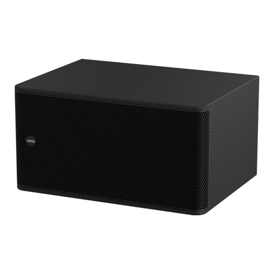
Summary of Contents for Void Venu V2 Series
- Page 1 Venu V2 Series More attractive and unexpecting than ever U S E R G U I D E V 2 . 0...
- Page 2 For the latest online version, visit: www.voidacoustics.com Void Acoustics and the Void logo are registered trademarks of Void Acoustics Research Ltd. in the United Kingdom, USA and other countries; all other Void trademarks are the property of Void Acoustics Research Ltd.
-
Page 3: Table Of Contents
Yoke Bracket Mounting Horn Rotation Low Frequency Enclosure Wall Mount Low Frequency Enclosure Ceiling Mount Top Hat Installation for Low Frequency Enclosures 5.10 Top Hat Installation for High Frequency Enclosures UG10579-2.0 - Venu V2 Series User Guide V2.0 Page 3... -
Page 4: Safety And Regulations
Void Acoustics Research Ltd for such as when the power-supply cord or plug is damaged, liquid reprocessing. -
Page 5: Unpacking And Checking
2 Unpacking and Checking All Void Acoustics products are carefully manufactured and thoroughly tested before being despatched. Your dealer will ensure that your Void products are in pristine condition before being forwarded to you but mistakes and accidents can happen. -
Page 6: About
In buying this product, you are now part of the Void family and we hope using it brings you years of satisfaction. This guide will help you both use this product safely and ensure it performs to its full capability. -
Page 7: Cable And Wiring
4 Cable and Wiring 4.1 Electrical safety To avoid electrical hazards please note the following: • Do not access the inside of any electrical equipment. Refer servicing to Void- approved service agents. 4.2 Cable considerations for fixed installations We recommend specifying installation-grade Low Smoke Zero Halogen (LSZH) cables for permanent installations. -
Page 8: Venu 6, 8, 10, 12 And 15 V2 Wiring
1” HF and 8” LF Link/out Venu 10 V2 1” HF and 10” LF Link/out Venu 12 V2 1” HF and 12” LF Link/out Venu 15 V2 1” HF and 15” LF Link/out UG10579-2.0 - Venu V2 Series User Guide V2.0 Page 8... -
Page 9: Venu 112 And 115 V2 Wiring
Figure 4.4: Dual low frequency loudspeaker wiring diagram speakON™ pins 1+/1- speakON™ pins 2+/2- Venu 212 V2 2 x 12” LF Link/out Venu 215 V2 2 x 15” LF Link/out UG10579-2.0 - Venu V2 Series User Guide V2.0 Page 9... -
Page 10: Venu 208 Wiring
2 x 8” LF Link/out 4.8 Venu V2 amplifier to Phoenix wiring Figure 4.6: Bias D1 Phoenix wiring Figure 4.7: Bias Q1/Q2 Phoenix wiring Figure 4.8: Bias Q5 speakON wiring UG10579-2.0 - Venu V2 Series User Guide V2.0 Page 10... -
Page 11: Venu V2 Amplifier To Speakon™ Wiring
Connecting a 4 core speakON™ cable directly from a Bias Q5 to a Venu V2 loudspeaker will short circuit the amplifier and cause it to go into protect. Use either a 2 core speakON™ cable or a patch panel to split the amplifier channels. UG10579-2.0 - Venu V2 Series User Guide V2.0 Page 11... -
Page 12: Mounting
• Use only Void-approved mounting equipment and accessories • Secondary safeties should be provided in all instances where cabinets are flying or fixing overhead and should conform to local regulations UG10579-2.0 - Venu V2 Series User Guide V2.0 Page 12... -
Page 13: Wall Mounting In Portrait Mode
Take care when mounting the bracket to the wall, making sure to use the correct fixing and that the wall can take the load. Figure 5.3: Deconstructing the bracket assembly UG10579-2.0 - Venu V2 Series User Guide V2.0 Page 13... - Page 14 Figure 5.6a: Bracket adjustment Maximum rotation Horizontal Vertical Venu 6 76° 40° Venu 8 70° 40° Venu 10 63° 40° Venu 12 72° 40° Venu 15 61° 40° Figure 5.6b: Bracket adjustment UG10579-2.0 - Venu V2 Series User Guide V2.0 Page 14...
-
Page 15: Wall Mounting In Landscape Mode
Take care when mounting the bracket to the wall, making sure to use the correct fixing and that the wall can take the load. Figure 5.9: Deconstructing the bracket assembly UG10579-2.0 - Venu V2 Series User Guide V2.0 Page 15... - Page 16 Figure 5.12a: Bracket adjustment Maximum rotation Horizontal Vertical Venu 6 65° 40° Venu 8 56° 40° Venu 10 85° 40° Venu 12 65° 40° Venu 15 33° 40° Figure 5.12b: Bracket adjustment UG10579-2.0 - Venu V2 Series User Guide V2.0 Page 16...
-
Page 17: High Frequency Enclosure Ceiling Mount
Figure 5.14: Venu bolt removal Step 2: Remove all four M8 bolts from the rear of the loudspeaker. Attach the bracket plate using all four M8 bolts. Figure 5.15: Fixing bracket UG10579-2.0 - Venu V2 Series User Guide V2.0 Page 17... - Page 18 Figure 5.16: Attaching bracket to loudspeaker Step 4: Tighten the M10 bolt on the bracket to fix the loudspeaker in position. Maximum vertical adjustment is 32°. Figure 5.17: Loudspeaker positioning UG10579-2.0 - Venu V2 Series User Guide V2.0 Page 18...
-
Page 19: Yoke Bracket Mounting
Fix the yoke into position by fitting the remaining bolts. Take care when mounting the yoke to the wall/ceiling, making sure to use the correct fixing and that it can take the load. Figure 5.20: Yoke fixing UG10579-2.0 - Venu V2 Series User Guide V2.0 Page 19... - Page 20 Fit the M8 bolts but do not tighten. Figure 5.22: Loudspeaker fitting Step 5: Rotate the loudspeaker into position and then tighten the bolts. Figure 5.23: Loudspeaker positioning UG10579-2.0 - Venu V2 Series User Guide V2.0 Page 20...
- Page 21 Fit the M8 bolts but do not tighten. Figure 5.22: Loudspeaker fitting Step 5: Rotate the loudspeaker into position and then tighten the bolts. Figure 5.23: Loudspeaker positioning UG10579-2.0 - Venu V2 Series User Guide V2.0 Page 21...
-
Page 22: Horn Rotation
Figure 5.25: Grill removal Step 3: Remove all four M5 bolts from around the horn. Figure 5.26: Removing horn screws UG10579-2.0 - Venu V2 Series User Guide V2.0 Page 22... - Page 23 Figure 5.28: Grille replacement Step 6: Rotate the badge to the desired orientation by lifting and turning 90°. The badge will locate automatically once in position. Figure 5.29: Badge rotation UG10579-2.0 - Venu V2 Series User Guide V2.0 Page 23...
-
Page 24: Low Frequency Enclosure Wall Mount
Figure 5.31: Nut removal Step 2: Remove all four M8 countersunk bolts from the bottom of the loudspeaker Figure 5.32: Bolt removal UG10579-2.0 - Venu V2 Series User Guide V2.0 Page 24... - Page 25 Raise the loudspeaker into position and attach the M12 nut. Figure 5.34: Loudspeaker fixing Step 6: Rotate the loudspeaker into the desired position and tighten the M12 bolt. Figure 5.35: Loudspeaker positioning UG10579-2.0 - Venu V2 Series User Guide V2.0 Page 25...
-
Page 26: Low Frequency Enclosure Ceiling Mount
Remove the type 75 plate from the T75 - Ceiling Bracket by removing the M12 bolt. Figure 5.37: Nut removal Step 2: Remove all four M8 counter sink bolts from the bottom of the loudspeaker Figure 5.38: Bolt removal UG10579-2.0 - Venu V2 Series User Guide V2.0 Page 26... - Page 27 Raise the loudspeaker into position and attach the M12 nut. Figure 5.40: Loudspeaker fixing Step 6: Rotate the loudspeaker into the desired position and tighten the M12 bolt. Figure 5.41: Loudspeaker positioning UG10579-2.0 - Venu V2 Series User Guide V2.0 Page 27...
-
Page 28: Top Hat Installation For Low Frequency Enclosures
Remove all four M6 bolts and remove the cover plate. Figure 5.43: Cover plate removal Step 2: Insert the Heavy Duty Top Hat and replace all four M6 bolts. Figure 5.44: Top hat placement UG10579-2.0 - Venu V2 Series User Guide V2.0 Page 28... -
Page 29: Top Hat Installation For High Frequency Enclosures
Remove all three M6 bolts and remove the cover plate. Figure 5.46: Cover plate removal Step 2: Insert the Venu V2 Top Hat and replace all three M6 bolts. Figure 5.47: Top hat placement UG10579-2.0 - Venu V2 Series User Guide V2.0 Page 29... -
Page 30: 6 Service
Before returning your faulty product for repair, please remember to get an R.A.N. (Return Authorisation Number) from the Void dealer who supplied the system to you. Your dealer will handle the necessary paperwork and repair. Failure to go through this return authorisation procedure could delay the repair of your product. -
Page 31: 7 Appendix A: Specifications
4 x M8 fixing points for type 80 plate Optional top hat Measured in half space AES2 - 1984 compliant Calculated Figure A.1: Horizontal directivity isobars Figure A.2: Vertical directivity isobars UG10579-2.0 - Venu V2 Series User Guide V2.0 Page 31... - Page 32 4 x M8 fixing points for type 80 plate Optional top hat Measured in half space AES2 - 1984 compliant Calculated Figure A.3: Horizontal directivity isobars Figure A.4: Vertical directivity isobars UG10579-2.0 - Venu V2 Series User Guide V2.0 Page 32...
- Page 33 4 x M8 fixing points for type 80 plate Optional top hat Measured in half space AES2 - 1984 compliant Calculated Figure A.5: Horizontal directivity isobars Figure A.6: Vertical directivity isobars UG10579-2.0 - Venu V2 Series User Guide V2.0 Page 33...
- Page 34 4 x M8 fixing points for type 80 plate Optional top hat Measured in half space AES2 - 1984 compliant Calculated Figure A.7: Horizontal directivity isobars Figure A.8: Vertical directivity isobars UG10579-2.0 - Venu V2 Series User Guide V2.0 Page 34...
- Page 35 4 x M8 fixing points for type 80 plate Optional top hat Measured in half space AES2 - 1984 compliant Calculated Figure A.9: Horizontal directivity isobars Figure A.10: Vertical directivity isobars UG10579-2.0 - Venu V2 Series User Guide V2.0 Page 35...
- Page 36 4 x M8 bolts for type 75 plate Optional M20 top hat for pole mount Measured in half space AES2 - 1984 compliant Calculated Frequency (Hz) Figure A.11: Venu 112 V2 impedance graph UG10579-2.0 - Venu V2 Series User Guide V2.0 Page 36...
- Page 37 Perforated steel with foam filter Mounting Yoke bracket positions Optional M20 top hat for pole mount Measured in half space AES2 - 1984 compliant Calculated Frequency (Hz) Figure A.12: Venu 212 V2 impedance graph UG10579-2.0 - Venu V2 Series User Guide V2.0 Page 37...
- Page 38 4 x M8 bolts for type 75 plate Optional M20 top hat for pole mount Measured in half space AES2 - 1984 compliant Calculated Frequency (Hz) Figure A.13: Venu 115 V2 impedance graph UG10579-2.0 - Venu V2 Series User Guide V2.0 Page 38...
- Page 39 Perforated steel with foam filter Mounting Optional M20 top hat for pole mount Measured in half space AES2 - 1984 compliant Calculated Frequency (Hz) Figure C.4: Venu 215 impedance graph UG10579-2.0 - Venu V2 Series User Guide V2.0 Page 39...
- Page 40 Textured polyurethane Grille Perforated steel with foam filter Mounting Yoke bracket and type 75 plate positions Measured in half space AES2 - 1984 compliant Calculated Figure C.5: Venu 208 impedance graph UG10579-2.0 - Venu V2 Series User Guide V2.0 Page 40...
-
Page 41: 8 Appendix B: Dimensions
M8 Fixtures 151 (5.9") Figure B.1: Venu 6 V2 dimensions B.2 Venu 8 V2 dimensions 218 (8.6") 245 (9.6") 228 (9.0") M8 Fixtures 160 (6.3") Figure B.2: Venu 8 V2 dimensions UG10579-2.0 - Venu V2 Series User Guide V2.0 Page 41... - Page 42 250 (9.8") 260 (10.2") M8 Fixtures 212 (8.4") Figure B.3: Venu 10 V2 dimensions B.4 Venu 12 V2 dimensions 370(14.6") 330(13.0") 340(13.4") M8 Fixtures 234(9.2") Figure B.4: Venu 12 V2 dimensions UG10579-2.0 - Venu V2 Series User Guide V2.0 Page 42...
- Page 43 384 (15.1") 300 (11.8") Figure B.5: Venu 15 V2 dimensions B.6 Venu 112 V2 dimensions M8 Fixtures 215(8.5") 490(19.3") 430(16.9") M8 Fixtures (4 POS) 51(2.0") Figure B.6: Venu 112 V2 dimensions UG10579-2.0 - Venu V2 Series User Guide V2.0 Page 43...
- Page 44 Figure B.7: Venu 212 V2 dimensions B.8 Venu 115 V2 dimensions M8 Fixtures 448 (17.6") 318 (12.5") 636 (25.0") M8 Fixtures (4 POS) 50.8(2.0") Figure B.8: Venu 115 V2 dimensions UG10579-2.0 - Venu V2 Series User Guide V2.0 Page 44...
- Page 45 B.9 Venu 208 V2 dimensions 600 23 " FIXING FOR YOKE BRACKET (SOLD SEPARATELY) FIXING FOR TYPE 75 PLATE (SOLD SEPARATELY) 108 4 " 246 9 " Figure B.10: Venu 208 V2 dimensions UG10579-2.0 - Venu V2 Series User Guide V2.0 Page 45...
-
Page 46: Specifications
M20 top-hat. External dimensions of (W) 224 mm x (H) 372 mm x (D) 202 mm (8.8” x 14.6” x 7.9”). Weight shall be 9.5 kg (20.9 lbs). The loudspeaker shall be the Void Acoustics Venu 6 V2. UG10579-2.0 - Venu V2 Series User Guide V2.0... - Page 47 M20 top-hat. External dimensions of (W) 245 mm x (H) 415 mm x (D) 228 mm (9.6” x 16.3” x 9”). Weight shall be 12 kg (26.5 lbs). The loudspeaker shall be the Void Acoustics Venu 8 V2. UG10579-2.0 - Venu V2 Series User Guide V2.0...
- Page 48 M20 top-hat. External dimensions of (W) 301 mm x (H) 469 mm x (D) 260 mm (11.9” x 18.5” x 10.2”). Weight shall be 16 kg (35.3 lbs). The loudspeaker shall be the Void Acoustics Venu 10 V2. UG10579-2.0 - Venu V2 Series User Guide V2.0...
- Page 49 M20 top-hat. External dimensions of (W) 370 mm x (H) 522 mm x (D) 340 mm (14.6” x 20.6” x 13.4”). Weight shall be 22 kg (48.5 lbs). The loudspeaker shall be the Void Acoustics Venu 12 V2. UG10579-2.0 - Venu V2 Series User Guide V2.0...
- Page 50 M20 top-hat. External dimensions of (W) 458 mm x (H) 670 mm x (D) 381 mm (18” x 26.4” x 15”). Weight shall be 31 kg (68.3 lbs). The loudspeaker shall be the Void Acoustics Venu 15 V2. UG10579-2.0 - Venu V2 Series User Guide V2.0...
- Page 51 101.6 mm (4”) voice, wound with copper wire on a high-quality voice coil former for high power handling and long-term reliability. The loudspeaker system shall be a Void Acoustics Venu 112 V2. UG10579-2.0 - Venu V2 Series User Guide V2.0...
- Page 52 101.6 mm (4”) voice, wound with copper wire on a high-quality voice coil former for high power handling and long-term reliability. The loudspeaker system shall be a Void Acoustics Venu 212 V2. UG10579-2.0 - Venu V2 Series User Guide V2.0...
- Page 53 101.6 mm (4”) voice, wound with copper wire on a high-quality voice coil former for high power handling and long-term reliability. The loudspeaker system shall be a Void Acoustics Venu 115 V2. UG10579-2.0 - Venu V2 Series User Guide V2.0...
- Page 54 In addition, a Neutrik speakON™ NL4 shall also feature. The loudspeaker system shall be a Void Acoustics Venu 215 V2. UG10579-2.0 - Venu V2 Series User Guide V2.0 Page 54...
- Page 55 50.8 mm (2”) voice coil, wound with copper wire on a high-quality voice coil former for high power handling and long-term reliability. The loudspeaker system shall be a Void Acoustics Venu 208 V2. UG10579-2.0 - Venu V2 Series User Guide V2.0...
- Page 56 IT1905 IT1140 Venu 212 IT2924 IT2923 IT2042 IT2041 Venu 115 IT2925 IT2926 IT1133 IT1132 IT2042 IT2041 IT1905 IT1140 Venu 215 IT2042 IT2041 Venu 208 IT3216 IT3215 IT1133 IT1132 IT1905 IT1140 UG10579-2.0 - Venu V2 Series User Guide V2.0 Page 56...
- Page 57 H E A D O F F I C E Void Acoustics Research Ltd, Unit 15, Dawkins Road Industrial Estate, Poole, Dorset, BH15 4JY United Kingdom Call: +44(0) 1202 666006 Email: info@voidacoustics.com voidacoustics.com Void Acoustics Research Limited is a company registered in England and Wales registration number 07533536...
Need help?
Do you have a question about the Venu V2 Series and is the answer not in the manual?
Questions and answers