Table of Contents
Advertisement
Advertisement
Table of Contents

Subscribe to Our Youtube Channel
Related Manuals for Void Venu V2 Series


Summary of Contents for Void Venu V2 Series
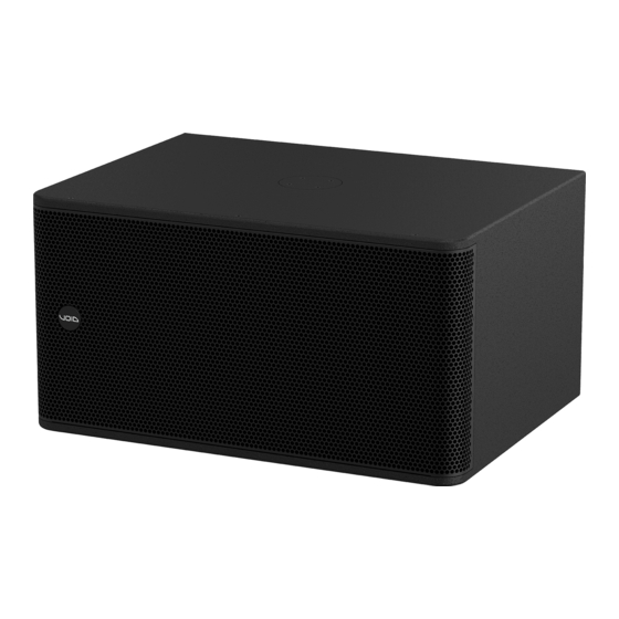
- Page 1 Venu V2 Series User Guide V1.0...
- Page 2 This user guide is subject to change without notice. For the latest online version, visit: www.voidacoustics.com Void Acoustics and the Void logo are registered trademarks of Void Acoustics Research Ltd. in the United Kingdom, USA and other countries; all other Void trademarks are the property of Void Acoustics...
-
Page 3: Table Of Contents
Venu to bass alignment Asymmetrical waveguide orientation Mounting Installation safety Wall mounting portrait mode Wall mounting in landscape mode High frequency enclosure ceiling mounting Yoke bracket mounting Horn rotation Low frequency enclosure wall mount Venu V2 Series User Guide V1.0 Page 3... -
Page 4: Safety And Regulations
Void Acoustics Research Ltd for While every care has been taken in creating this guide, safety is reprocessing. For more information about where you can send... -
Page 5: Limited Warranty
Venu V2 Series product (provided it was purchased make the defective or malfunctioning product at an Authorised Void Dealer) that it is free of available to Void free and clear of all liens or other defects in materials and workmanship and that each restrictions. -
Page 6: Unpacking And Checking
3 Unpacking and checking All Void Acoustics products are carefully manufactured and thoroughly tested before being dispatched. Your dealer will ensure that your Void products are in pristine condition before being forwarded to you but mistakes and accidents can happen. -
Page 7: Introduction
In buying this product, you are now part of the Void family and we hope using it brings you years of satisfaction. This guide will help you both use this product safely and ensure it performs to its full capability. -
Page 8: Cabling And Wiring
5 Cabling and wiring 5.1 Electrical safety To avoid electrical hazards please note the following: • Do not access the inside of any electrical equipment. Refer servicing to Void- approved service agents. 5.2 Cable considerations for fixed installations We recommend specifying installation-grade Low Smoke Zero Halogen (LSZH) cables for permanent installations. -
Page 9: Venu 6, 8, 10, 12 And 15 V2 Wiring
1” HF and 8” LF Link/out Venu 10 V2 1” HF and 10” LF Link/out Venu 12 V2 1” HF and 12” LF Link/out Venu 15 V2 1” HF and 15” LF Link/out Venu V2 Series User Guide V1.0 Page 9... -
Page 10: Venu 112 And 115 V2 Wiring
5.6 Venu 212 and 215 V2 wiring Figure 5.4: Dual low frequency loudspeaker wiring diagram speakON™ pins 1+/1- speakON™ pins 2+/2- Venu 212 V2 2 x 12” LF Link/out Venu 215 V2 2 x 15” LF Link/out Venu V2 Series User Guide V1.0 Page 10... -
Page 11: Venu V2 Amplifier To Phoenix
Figure 5.7: Bias Q5 Phoenix/speakON wiring Bias Q5 Output 1 Max parallel units (Venu 6/8/10/12/15/112/115 V2) 4 (2 load to amplifier) Max parallel units (Venu 212/215 V2) 2 (2 load to amplifier) Venu V2 Series User Guide V1.0 Page 11... -
Page 12: Venu V2 Amplifier To Speakon™ Wiring
Figure 5.10: Bias Q5 speakON wiring Bias Q5 Output 1 Max parallel units (Venu 6/8/10/12/15/112/115 V2) 4 (2 load to amplifier) Max parallel units (Venu 212/215 V2) 2 (2 load to amplifier) Venu V2 Series User Guide V1.0 Page 12... -
Page 13: System Design
Venu V2 loudspeakers can be arrayed as a single pair facing forward to provide a wide stereo image. Figure 6.1: Venu V2 Series loudspeakers single pair arrangement For applications requiring wide horizontal coverage, use two Venu V2 Series loudspeakers in pairs, angled at about 40°. -
Page 14: High Frequency Loudspeaker Placement
This is the most desirable position for the loudspeakers in this example. Figure 6.5: Correct loudspeaker placement Venu V2 Series User Guide V1.0 Page 14... - Page 15 Figure 6.6: Multi point loudspeaker arrangement In the horizontal plane rotate the Venu V2 Series loudspeakers toward the audience area at an angle such that the centre line of the dispersion from each loudspeaker meets about two thirds of the way towards the rear of the audience area.
- Page 16 6 System design Avoid directing the Venu V2 Series loudspeaker straight forward. This will result in a proportion of the power being directed towards the walls, creating possible reflective issues, as well as causing a gap in coverage at the centre of the audience area.
-
Page 17: Typical Operating Modes For Low
Although the modes of arrangement shown here are typical operating modes for low frequency enclosures, the Venu V2 Series low frequency enclosures design lends itself to wide range of configurations. Simple planer arrays and stacks to directional and steerable arrays are possible given suitable electronics and presets. -
Page 18: Frequency Enclosures
E to the north edge of the circle, and multiply by the delay time per metre. Or: (A - D) x 2.9 ms/m = delay time. Figure 6.14: Bass alignment example 2 Venu V2 Series User Guide V1.0 Page 18... -
Page 19: Asymmetrical Waveguide Orientation
Due to the asymmetrical nature of the high frequency waveguide it must be orientated correctly. The narrow end of the waveguide creates the wider dispersion and should always be facing down as shown in the figure below. Figure 6.15: Asymmetrical waveguide orientation Venu V2 Series User Guide V1.0 Page 19... -
Page 20: Mounting
• Do not rig equipment that is worn, damaged, corroded, mishandled or over-stressed in any way • Use only Void-approved mounting equipment and accessories • Secondary safeties should be provided in all instances where cabinets are flying or fixing overhead and should conform to local regulations Venu V2 Series User Guide V1.0... -
Page 21: Wall Mounting Portrait Mode
fixing and that the wall can take the load, for example do not attach the bracket to a stud wall. Figure 7.3: Deconstructing the bracket assembly Venu V2 Series User Guide V1.0 Page 21... - Page 22 (figure 7.6a) and in the vertical axis by adjusting the bolt on the base of the assembly (figure 7.6b). Figure 7.6a: Bracket adjustment Figure 7.6b: Bracket adjustment Venu V2 Series User Guide V1.0 Page 22...
-
Page 23: Wall Mounting In Landscape Mode
fixing and that the wall can take the load, for example do not attach the bracket to a stud wall. Figure 7.9: Deconstructing the bracket assembly Venu V2 Series User Guide V1.0 Page 23... - Page 24 (figure 7.12a) and in the vertical axis by adjusting the bolt on the base of the assembly (figure 7.12b). Figure 7.12a: Bracket adjustment Figure 7.12b: Bracket adjustment Venu V2 Series User Guide V1.0 Page 24...
-
Page 25: High Frequency Enclosure Ceiling
fixing and that the ceiling can take the load, for example do not attach the bracket to a suspended ceiling. Figure 7.15: Fixing bracket Venu V2 Series User Guide V1.0 Page 25... - Page 26 Figure 7.16: Attaching bracket to loudspeaker Step 4: Tighten the bolt on the bracket to fix the loudspeaker in position. Figure 7.17: Loudspeaker positioning Venu V2 Series User Guide V1.0 Page 26...
-
Page 27: Yoke Bracket Mounting
fixing and that it can take the load, for example do not attach the yoke to a stud wall. Figure 7.20: Yoke fixing Venu V2 Series User Guide V1.0 Page 27... - Page 28 M8 bolts supplied with the yoke bracket. Fit the M8 bolts but do not tighten. Figure 7.22: Loudspeaker fitting Step 5: Rotate the loudspeaker into position and then tighten the bolts. Figure 7.23: Loudspeaker positioning Venu V2 Series User Guide V1.0 Page 28...
-
Page 29: Horn Rotation
Figure 7.25: Grill removal Step 3: Remove all four M5 bolts from around the horn. Figure 7.26: Removing horn screws Venu V2 Series User Guide V1.0 Page 29... - Page 30 M4 bolts in the side. Figure 7.28: Grille replacement Step 6: Rotate the badge to the desired orientation by lifting and turning 90°. The badge will locate automatically once in position. Figure 7.29: Badge rotation Venu V2 Series User Guide V1.0 Page 30...
-
Page 31: Low Frequency Enclosure Wall Mount
Figure 7.31: Nut removal Step 2: Remove all four M8 countersunk bolts from the bottom of the loudspeaker Figure 7.32: Bolt removal Venu V2 Series User Guide V1.0 Page 31... - Page 32 Raise the loudspeaker into position and attach the M12 nut. Figure 7.34: Loudspeaker fixing Step 6: Rotate the loudspeaker into the desired position and tighten the M12 bolt. Figure 7.35: Loudspeaker positioning Venu V2 Series User Guide V1.0 Page 32...
- Page 33 Remove the type 75 plate from the Air series ceiling bracket by removing the M12 bolt. Figure 7.37: Nut removal Step 2: Remove all four M8 counter sink bolts from the bottom of the loudspeaker Figure 7.38: Bolt removal Venu V2 Series User Guide V1.0 Page 33...
- Page 34 Raise the loudspeaker into position and attach the M12 nut. Figure 7.40: Loudspeaker fixing Step 6: Rotate the loudspeaker into the desired position and tighten the M12 bolt. Figure 7.41: Loudspeaker positioning Venu V2 Series User Guide V1.0 Page 34...
- Page 35 Remove all four M6 bolts and remove the cover plate. Figure 7.43: Cover plate removal Step 2: Insert the Heavy Duty Top Hat and replace all four M6 bolts. Figure 7.44: Top hat placement Venu V2 Series User Guide V1.0 Page 35...
- Page 36 Remove all three M6 bolts and remove the cover plate. Figure 7.46: Cover plate removal Step 2: Insert the Venu V2 Top Hat and replace all three M6 bolts. Figure 7.47: Top hat placement Venu V2 Series User Guide V1.0 Page 36...
- Page 37 Before returning your faulty product for repair, please remember to get an R.A.N. (Return Authorisation Number) from the Void dealer who supplied the system to you. Your dealer will handle the necessary paperwork and repair. Failure to go through this return authorisation procedure could delay the repair of your product.
-
Page 38: Appendix A: Specifications
Yoke bracket positions 4 x M8 fixing points for type 80 plate Optional top hat Measured in half space AES2 - 1984 compliant Calculated Figure A.1: Horizontal directivity isobars Figure A.2: Vertical directivity isobars Venu V2 Series User Guide V1.0 Page 38... - Page 39 Yoke bracket positions 4 x M8 fixing points for type 80 plate Optional top hat Measured in half space AES2 - 1984 compliant Calculated Figure A.3: Horizontal directivity isobars Figure A.4: Vertical directivity isobars Venu V2 Series User Guide V1.0 Page 39...
- Page 40 Yoke bracket positions 4 x M8 fixing points for type 80 plate Optional top hat Measured in half space AES2 - 1984 compliant Calculated Figure A.5: Horizontal directivity isobars Figure A.6: Vertical directivity isobars Venu V2 Series User Guide V1.0 Page 40...
- Page 41 Yoke bracket positions 4 x M8 fixing points for type 80 plate Optional top hat Measured in half space AES2 - 1984 compliant Calculated Figure A.7: Horizontal directivity isobars Figure A.8: Vertical directivity isobars Venu V2 Series User Guide V1.0 Page 41...
- Page 42 Yoke bracket positions 4 x M8 fixing points for type 80 plate Optional top hat Measured in half space AES2 - 1984 compliant Calculated Figure A.9: Horizontal directivity isobars Figure A.10: Vertical directivity isobars Venu V2 Series User Guide V1.0 Page 42...
- Page 43 4 x M8 bolts for type 75 plate Optional M20 top hat for pole mount Measured in half space AES2 - 1984 compliant Calculated Frequency (Hz) Figure A.11: Venu 112 V2 impedance graph Venu V2 Series User Guide V1.0 Page 43...
- Page 44 Perforated steel with foam filter Rigging Yoke bracket positions Optional M20 top hat for pole mount Measured in half space AES2 - 1984 compliant Calculated Frequency (Hz) Figure A.12: Venu 212 V2 impedance graph Venu V2 Series User Guide V1.0 Page 44...
- Page 45 4 x M8 bolts for type 75 plate Optional M20 top hat for pole mount Measured in half space AES2 - 1984 compliant Calculated Frequency (Hz) Figure A.13: Venu 115 V2 impedance graph Venu V2 Series User Guide V1.0 Page 45...
- Page 46 Textured polyurethane Grill Perforated steel with foam filter Rigging Optional M20 top hat for pole mount Measured in half space AES2 - 1984 compliant Calculated Frequency (Hz) Figure C.4: Venu 215 impedance graph Venu V2 Series User Guide V1.0 Page 46...
- Page 47 10 Appendix B: Dimensions B.1 Venu 6 V2 dimensions (4 POS) Figure B.1: Venu 6 V2 dimensions B.2 Venu 8 V2 dimensions (4 POS) Figure B.2: Venu 8 V2 dimensions Venu V2 Series User Guide V1.0 Page 47...
- Page 48 10 Appendix B: Dimensions B.3 Venu 10 V2 dimensions (4 POS) Figure B.3: Venu 10 V2 dimensions B.4 Venu 12 V2 dimensions (4 POS) Figure B.4: Venu 12 V2 dimensions Venu V2 Series User Guide V1.0 Page 48...
- Page 49 10 Appendix B: Dimensions B.5 Venu 15 V2 dimensions (4 POS) (4 POS) (4 POS) Figure B.5: Venu 15 V2 dimensions B.6 Venu 112 V2 dimensions Figure B.6: Venu 112 V2 dimensions Venu V2 Series User Guide V1.0 Page 49...
- Page 50 10 Appendix B: Dimensions B.7 Venu 212 V2 dimensions Figure B.7: Venu 212 V2 dimensions B.8 Venu 115 V2 dimensions 448 (17.6”) 448 (17.6”) 636 (25”) 448 (17.6”) Figure B.8: Venu 115 V2 dimensions Venu V2 Series User Guide V1.0 Page 50...
- Page 51 10 Appendix B: Dimensions B.9 Venu 215 V2 dimensions Figure B.9: Venu 215 V2 dimensions Venu V2 Series User Guide V1.0 Page 51...
-
Page 52: Appendix C: Architectural Specifications
M20 top-hat. External dimensions of (W) 224 mm x (H) 372 mm x (D) 202 mm (8.8” x 14.6” x 7.9”). Weight shall be 9.5 kg (20.9 lbs). The loudspeaker shall be the Void Acoustics Venu 6 V2. Venu V2 Series User Guide V1.0... - Page 53 M20 top-hat. External dimensions of (W) 245 mm x (H) 415 mm x (D) 228 mm (9.6” x 16.3” x 9”). Weight shall be 12 kg (26.5 lbs). The loudspeaker shall be the Void Acoustics Venu 8 V2. Venu V2 Series User Guide V1.0...
- Page 54 M20 top-hat. External dimensions of (W) 301 mm x (H) 469 mm x (D) 260 mm (11.9” x 18.5” x 10.2”). Weight shall be 16 kg (35.3 lbs). The loudspeaker shall be the Void Acoustics Venu 10 V2. Venu V2 Series User Guide V1.0...
- Page 55 M20 top-hat. External dimensions of (W) 370 mm x (H) 522 mm x (D) 340 mm (14.6” x 20.6” x 13.4”). Weight shall be 22 kg (48.5 lbs). The loudspeaker shall be the Void Acoustics Venu 12 V2. Venu V2 Series User Guide V1.0...
- Page 56 M20 top-hat. External dimensions of (W) 458 mm x (H) 670 mm x (D) 381 mm (18” x 26.4” x 15”). Weight shall be 31 kg (68.3 lbs). The loudspeaker shall be the Void Acoustics Venu 15 V2. Venu V2 Series User Guide V1.0...
- Page 57 101.6 mm (4”) voice, wound with copper wire on a high-quality voice coil former for high power handling and long-term reliability. The loudspeaker system shall be a Void Acoustics Venu 112 V2. Venu V2 Series User Guide V1.0...
- Page 58 101.6 mm (4”) voice, wound with copper wire on a high-quality voice coil former for high power handling and long-term reliability. The loudspeaker system shall be a Void Acoustics Venu 212 V2. Venu V2 Series User Guide V1.0...
- Page 59 101.6 mm (4”) voice, wound with copper wire on a high-quality voice coil former for high power handling and long-term reliability. The loudspeaker system shall be a Void Acoustics Venu 115 V2. Venu V2 Series User Guide V1.0...
- Page 60 (this connector should then screw lock to the enclosure for secure attachment). In addition, a Neutrik speakON™ NL4 shall also feature. The loudspeaker system shall be a Void Acoustics Venu 215 V2. Venu V2 Series User Guide V1.0 Page 60...
- Page 61 IT2941 IT1106 IT1105 IT2765 Venu 112 IT1115 IT1114 IT2921 IT2920 IT1133 IT1132 IT2042 IT2041 Venu 212 IT2924 IT2923 IT2042 IT2041 Venu 115 IT2925 IT2926 IT1133 IT1132 IT2042 IT2041 Venu 215 IT2042 IT2041 Venu V2 Series User Guide V1.0 Page 61...
- Page 64 North America Void Acoustics North America 503-854-7134 sales.usa@voidacoustics.com Head Office Void Acoustics Research Ltd Unit 15 Dawkins Road Industrial Estate Poole Dorset BH15 4JY England +44 (0) 1202 666 006 info@voidacoustics.com Registered in England & Wales No. 07533536 www.voidacoustics.com...
Need help?
Do you have a question about the Venu V2 Series and is the answer not in the manual?
Questions and answers