
Related Manuals for Zeiss VISUCAM C


Summary of Contents for Zeiss VISUCAM C
- Page 1 VISUCAM C DigitalCamera Gebrauchsanweisung User´s Manual Mode d’emploi Instrucciones de uso...
-
Page 3: Copyright
Violations will entail an obligation to pay compensation. All rights reserved in the event of granting of patents or registration of a utility model. 000000-1253-546 VISUCAM C 31.07.2003... -
Page 4: Trade Mark
In general, other brand names as well as names of software and hardware products are subject to trademark or patent protection. Quoting of product names is for information only and does not represent any trademark misuse. 000000-1253-546 VISUCAM C 31.07.2003... -
Page 5: Table Of Contents
Data backup ..............8 Correct use of the instrument............8 Instrument Description..............9 Design of basic unit..............9 Controls of the VISUCAM C ............10 Connector panel of the VISUCAM C.......... 13 Power isolation transformer for external devices ......14 Start-up..................15 Installation ............... - Page 6 Printing images................49 Printing from the Patient Manager mode......49 Export of image data ..............51 Import/export patient list ............53 Switching off the VISUCAM C ...........54 Care and Maintenance..............55 Changing the bulb..............56 Changing the halogen lampe ...........56 Replacing the blinking diode of the fixation lamp .....57 Maintenance notes ..............59...
-
Page 7: Safety Notes
Please see Fig. 3 and Fig. 4 for positions of warning and information signs. Warning Correct operation of the VISUCAM C Digital Camera is imperative for its safe function. Therefore, please read these operating instructions thoroughly before using the instrument. -
Page 8: Notes On Installation And Use
Notes on installation and use ❏ Only appropriately qualified or trained persons are allowed to operate the VISUCAM C. ❏ Always keep the user’s manual at hand for reference. ❏ Make sure to avoid uncontrolled looking at the light source, for instance at the objective! Risk of dazzling! ❏... - Page 9 ❏ While no acute optical radiation hazards have been identified for the VISUCAM C, it is recommended that the intensity of light directed into the patient’s eye be limited to a minimum level which is necessary for diagnosis.
-
Page 10: Safe Function
Correct use of the instrument The VISUCAM C DigitalCamera is suitable for photographing, displaying and storing the data of the retina and surrounding parts of the eye to be examined. These photographs support the diagnosis and subsequent observation of eye diseases which can be visually monitored and photographically documented. -
Page 11: Instrument Description
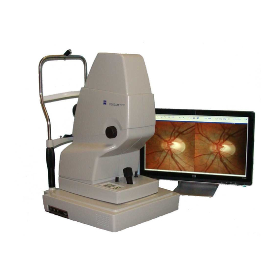
Keyboard and mouse for the entry of patient data and operation of the instrument Instrument base with joystick positioning of camera head, controls for lamp brightness and headrest Camera head containing illumination and viewing system with filters and image sensors Fig. 1 Design of basic instrument 000000-1253-546 VISUCAM C 31.07.2003... -
Page 12: Controls Of The Visucam C
Instrument Description Controls of the VISUCAM C Fig. 2 Controls of the VISUCAM C, view from the right 000000-1253-546 VISUCAM C 31.07.2003... - Page 13 Instrument Description In the right-hand view of the VISUCAM C, the following controls and components are shown (Fig. 2): 1 Lid of lamp housing 2 Inside fixation device (optional accessory) 3 Fastening pins for paper pads 4 Knurled knob for locking the instrument base...
- Page 14 Instrument Description Fig. 3 Controls of the VISUCAM C, view from the left 000000-1253-546 VISUCAM C 31.07.2003...
-
Page 15: Connector Panel Of The Visucam C
Instrument Description In the left-hand view of the VISUCAM C, the following controls and components are shown (Fig. 3): 1 Sleeve nut for fixation lamp 2 Forehead strap for the patient 3 Red eye level marks (patient eye level needed for optimum... -
Page 16: Power Isolation Transformer For External Devices
Non-compliance presents a violation of the regulations for the use of medical devices as per DIN EN 60601-1-1. Power cable connector with If you use the IT 3L or IT 2S Instrument Table from Carl Zeiss for the fuses VISUCAM C, the power isolation transformer can be mounted to the Power switch underside of the tabletop. -
Page 17: Start-Up
(1, Fig. 5) to separate permanently installed mains power outlets. The VISUCAM C is switched on by the power switch (1, Fig. 4) located on the connector panel). The external units printer and monitor are connected and switched on via the power isolation transformer. - Page 18 The instrument must be switched off when plugging and unplugging the USB cable. Note If the VISUCAM C is used in connection with a Carl Zeiss instrument table, the cable connections must be properly secured with cable clamps and laid in the cable ducts provided.
-
Page 19: Optional Accessories
Optional accessories Printer The printer is used to print the captured images. It is connected either to a free USB port of the VISUCAM C (4, Fig. 4) or the conventional parallel port LPT1. Caution For operation, observe the corresponding user’s manual provided by the manufacturer. -
Page 20: Functional Description
Instrument Description Functional description The VISUCAM C allows the representation of the fundus of the eye with the pupil being dilated. Easy operation of the camera provides quick findings. The camera is particularly suitable for routine use. The fundus of the eye can be assessed on the live image or the higher-quality single image. -
Page 21: Software Description
Make sure to read and observe the information provided in the section Safety Notes. Operation of the computer of the VISUCAM C is based on the Windows 98 SE operating system. For safety reasons, the operating system user interface is not accessible to the user. -
Page 22: Operation Via Keyboard And Mouse
Selection of several adjacent objects SHIFT Underlined letter key + Activation of menu command Activation of a specific button Underlined letter key on Image Capture desktop key in Image Capture desktop Release of image capture with light ENTER pulse 000000-1253-546 VISUCAM C 31.07.2003... -
Page 23: Screen Layout
Screen layout Overview The instrument software uses two windows for the operation of the VISUCAM C as well as several small dialog boxes and the survey window to aid positioning. On activation, the program will appear with activated Patient Manager desktop. - Page 24 Toolbar with icons directly below the menu bar Function buttons on Patient Manager desktop and function buttons and large display field for image presentation on Image Capture desktop Thumbnails of captured images Status bar Patient to be examined: at bottom edge of window 000000-1253-546 VISUCAM C 31.07.2003...
-
Page 25: Overview Of Menus And Icons
CD-R/RW drive Print Settings Print the screen Opens dialog window for user- specific setting program features Export Opens dialog window exporting selected images System Opens the System dialog window with a password Quit Quit program + Windows 000000-1253-546 VISUCAM C 31.07.2003... - Page 26 DICOM (*.dcm), JPEG (*.jpg) and bitmap (*.bmp) Deletes the selected images and video clips Opens the Customizing dialog Allows various settings to be customized Opens the online help window 000000-1253-546 VISUCAM C 31.07.2003...
-
Page 27: Patient Manager Desktop
Field for displaying the relevant data of the selected visit Button for discharging a patient from the patient room Button for deleting a selected visit Button for deleting a selected patient Fig. 11 Function buttons and display fields in the Patient Manager desktop 000000-1253-546 VISUCAM C 31.07.2003... -
Page 28: Image Capture Desktop
5 Display of selected patient eye 6 Bar-graph display of lamp brightness 7 Button for activating/deactivating the LED front light 8 Overview window the control camera image to aid positioning Fig. 12 Buttons on Image Capture desktop 000000-1253-546 VISUCAM C 31.07.2003... - Page 29 16 Button for stopping video clip records 17 Field for the display of frame rate and residual time of image capture Fig. 13 Bottom button bar for capturing single images Fig. 14 Bottom button bar for video clip recording 000000-1253-546 VISUCAM C 31.07.2003...
-
Page 30: Configuration Dialog Boxes
Opening of the System dialog box requires the entry of a password. Afterwards, you can activate the desired Windows function by a click on the corresponding button. Note Only users with appropriate experience in PC usage should modify the system settings. Fig. 15 System dialog box 000000-1253-546 VISUCAM C 31.07.2003... -
Page 31: User-Specific Program Settings
• Confirm your entries by a click on the button (data will be saved) or abort the setting procedure by a click on the button CANCEL (previous changes will not be saved and applied). Fig. 17 Customizing dialog box: Printing tab 000000-1253-546 VISUCAM C 31.07.2003... - Page 32 • Confirm your entries by a click on the button (data will be saved) or abort the setting procedure by a click on the button CANCEL (previous changes will not be saved and applied). Fig. 18 Customizing dialog box: General Information tab 000000-1253-546 VISUCAM C 31.07.2003...
- Page 33 CANCEL (previous changes will not be saved and applied). Note Please note that some of the settings will become effective only after restart of the system. Fig. 19 Customizing dialog box: User Interface tab 000000-1253-546 VISUCAM C 31.07.2003...
- Page 34 • If the image data are to be exported simultaneously during image capture, activate this check box as well. Fig. 20 Customizing dialog box: Import / Export tab 000000-1253-546 VISUCAM C 31.07.2003...
- Page 35 • Choose the maximum period of video clip recording (1 to 300 seconds). The longer the recording process the higher is the volume of data. • If requested, choose the Automatic Image Enhancement option for the lossless optimization of the contrast of the recorded images. 000000-1253-546 VISUCAM C 31.07.2003...
- Page 36 • Confirm your entries by a click on the button (data will be saved) or abort the setting procedure by a click on the button CANCEL (previous changes will not be saved and applied). Fig. 21 Customizing dialog box: Capture tab 000000-1253-546 VISUCAM C 31.07.2003...
-
Page 37: Survey Of Operating Procedure
– Export or print the selected images. Note When exporting images, check target folder. Before printing, you can use the preview function to check the contents of the printout. It is also possible to print from the Image comparison and correction tab. 000000-1253-546 VISUCAM C 31.07.2003... -
Page 38: Operation
Switching the instrument on • Switch on external instruments at the power isolation transformer. • Switch on the VISUCAM C at the power switch of the basic unit. – The system starts automatically, runs a self-test and then displays the Patient Manager desktop. -
Page 39: Patient Selection
TAKE INTO… transferred into the Waiting Room display field. The days patients are collected in the waiting room. • To open the Image Capture desktop, click on the Image capture icon. Fig. 23 Patient Manager desktop 000000-1253-546 VISUCAM C 31.07.2003... -
Page 40: Choosing The Image Capture Mode
(dilation of patient’s pupils using drugs not necessary), activate the Infrarot button. The display Eye: indicates the position of the VISUCAM C in front of the patient’s left or right eye: OS or OD (Oculus Sinister / Oculus Dexter). The bar-graph display in this field informs about lamp brightness (1 ... - Page 41 (see 13, Fig. 13). This new start value is then always defaulted when the software is restarted. Note The button ( ) is only available when the check box Enable change light pulse start values is activated, see program settings - Capture, page 34. 000000-1253-546 VISUCAM C 31.07.2003...
-
Page 42: Adjusting The Instrument To The Patient
Note The position of the light ring in the pupil cannot be correctly assessed in the survey window until the VISUCAM C is at the right distance from the patient’s eye. • Turn the focusing control to focus onto the fundus. -
Page 43: Adjusting The Instrument To The Patient By Infrared Observation
(sharp focus is indicated by a narrow ring). Adjusting the VISUCAM C: • Check whether the infrared light is active. • With the lens cap still attached, move the instrument base laterally to align it to either left or right eye. - Page 44 (very important) until the reflection disappears from the visible image. • Pull back the VISUCAM C about 1 mm from the patient’s eye (the reflection may not become visible again). • Release image capture by pressing the pushbutton on the joystick.
-
Page 45: Capturing Images
The instrument base is equipped with a special sensor for right eye / left eye detection. When you reposition the VISUCAM C from the right to the left patient eye, the new position will be automatically indicated on the monitor. The current position is included in the comment of image capture (OS / OD). -
Page 46: Red Images
Release image capture by pressing the pushbutton on the joystick. Note If eye movements during image capture cause out of focus images, it is possible to freeze and store the image with the SNAP switch (10, Fig. 13). 000000-1253-546 VISUCAM C 31.07.2003... -
Page 47: Presentation Of Images
On doing so, the image is being enlarged. To reduce it again, double-click once more. Then, you can choose the next thumbnail image. For a detailed observation of several images please use the Image comparison / corrrection tab. 000000-1253-546 VISUCAM C 31.07.2003... -
Page 48: Image Comparison And Image Correction
If more images are chosen than can be displayed at once in the selected split presentation, a scroll bar appears at the right of the dialog box with which all the images can be reached. 000000-1253-546 VISUCAM C 31.07.2003... - Page 49 Move image backwards icon. The image is moved one position backwards. Move image forwards: Activate the image with a mouse click and then click on the Move image forwards icon. The image is moved one position forwards. 000000-1253-546 VISUCAM C 31.07.2003...
- Page 50 This guarantees that the original state of the images is retained at all times. If you wish to keep changes, please use the Copy image function. With you return to the Patient Manager or from the Printing layout mode to the Print preview. 000000-1253-546 VISUCAM C 31.07.2003...
-
Page 51: Printing Images
To install a printer, activate the menu command File – System… . After entry of the password, click on the button. PRINTER Note Please only use printers recommended by Zeiss. Basic settings have to made in the System sub-menu for some printers. 000000-1253-546 VISUCAM C 31.07.2003... - Page 52 Changed images are printed as displayed. The Zoom function is for viewing only. The image is reset to its original size for printing. Please note that you can only access the print preview from the printing layout. 000000-1253-546 VISUCAM C 31.07.2003...
-
Page 53: Export Of Image Data
• Choose the folder or storage medium via the Folder list box. • Confirm the proposed file name or edit the name as desired. For unmistakable identification, the proposed file name contains the name, first name and the date of birth of the patient. 000000-1253-546 VISUCAM C 31.07.2003... - Page 54 LED on the USB Flash Drive is alight. The instrument must be switched off when plugging or unplugging the USB cable. 000000-1253-546 VISUCAM C 31.07.2003...
-
Page 55: Import/Export Patient List
The current patient list of the instrument can be exported from the instrument by using the menu command Extras – Export Patient List. Note Regularly use the export function for data backup to prevent any data loss. 000000-1253-546 VISUCAM C 31.07.2003... -
Page 56: Switching Off The Visucam C
Operation Switching off the VISUCAM C • To exit the software, activate the menu command File – Quit. This will bring up the Delete Options dialog box (Fig. 30). In this dialog box, you can take your choice which of the images shall be deleted. -
Page 57: Care And Maintenance
Such tampering will also forfeit any rights to claim under warranty. The maintenance work you may carry out yourself is described below. Please use original Zeiss components only. Note To restart the system after inadvertent switch-off at the power switch or after a system crash during operation, switch on the instrument again at the power switch. -
Page 58: Changing The Bulb
Fig. 32. • Remove the defective halogen lamp (1, Fig. 32, catalog number 409-306) from holder (3, Fig. 32) by pulling it upward. • Remove defective halogen lamp from lamp socket (2, Fig. 32). 000000-1253-546 VISUCAM C 31.07.2003... -
Page 59: Replacing The Blinking Diode Of The Fixation Lamp
Holder of the blinking diode Fig. 33 Replacement of blinking diode • Unscrew defective blinking diode (1, Fig. 33, catalog number 301350-9052) from holder (2, Fig. 33) and replace it by a new one. Only use original blinking diodes. 000000-1253-546 VISUCAM C 31.07.2003... - Page 60 • Replace defective fuse (2, Fig. 34). Reinsert the fuse insert with the fuse. Take care that the snap-in clip of the fuse insert is correctly positioned. Cover Fuse Fuse carrier Snap-in mechanism Fig. 34 Replacement of fuses on power isolation transformer 000000-1253-546 VISUCAM C 31.07.2003...
-
Page 61: Maintenance Notes
❏ Keep the packaging material for future relocation or repair. On request, you may also return it to the supplier. Disposal The instrument system contains electronic components. The instrument must be disposed of properly when it reaches the end of its service life. 000000-1253-546 VISUCAM C 31.07.2003... -
Page 62: Troubleshooting Table
Section Replacing Lamps on page 56 Observation brightness not Lamp control faulty Call technical service continuously adjustable Fixation light is dark Blinking diode faulty Replace blinking diode as described in section Replacing Lamps on page 57 000000-1253-546 VISUCAM C 31.07.2003... -
Page 63: Technical Data
5 kg Image capture angle Image angle 45° and 25° Ametropia compensation +25 dpt ... -25 dpt continuous Max. no. of images 1.4 images per second Filter green, red and infrared filter Specifications are subject to change. 000000-1253-546 VISUCAM C 31.07.2003... -
Page 64: Manufacturer's Declaration
DICOM Conformance Statement The manufacturer supports the export of images in the file format in conformance with the DICOM 3.0 Standard (Visible Light (VL) Photographic Image Storage). The DICOM Conformance Statement can be requested from the manufacturer. 000000-1253-546 VISUCAM C 31.07.2003... -
Page 65: Index
Disposal....................59 Electrical connection ................15 Export....................32 Fixation device ..................17 Functional description.................18 General information ................30 GREEN images (REDFREE)..............43 Icons....................23 Image Capture..................33 Image capture mode..............38, 43 Image comparison ................46 Image correction.................46 Image export ..................51 Import ....................32 Infrared observation................41 Installation....................6 000000-1253-546 VISUCAM C 31.07.2003... - Page 66 Screen layout ..................21 Software description ................19 Standards .................... 5 Start-up ..................... 15 Switching the instrument on .............. 36 Technical data..................61 Troubleshooting table ................ 60 USB flash drive................... 17 Use ...................... 8 User interface ..................31 000000-1253-546 VISUCAM C 31.07.2003...
- Page 68 CARL ZEISS MEDITEC AG Goeschwitzer Str. 51-52 D-07745 Jena Germany Phone: +49 3641 220 - 333 Fax: +49 3641 220 - 282 000000-1253-546 Email: info@meditec.zeiss.com VISUCAM C 31.07.2003 Internet: www.meditec.zeiss.com Specifications subject to change...
Need help?
Do you have a question about the VISUCAM C and is the answer not in the manual?
Questions and answers