Table of Contents
Advertisement
Service Instructions
Service Instructions
SM-30-4044-A1-en
SM-30-4044-A1-en
22.09.2003
22.09.2003
Issue:
Issue:
Replaces issue:
Replaces issue:
-
-
VISUCAM
VISUCAM
(effective from Oct. 2003)
(effective from Oct. 2003)
Fundus Camera
Fundus Camera
lite
lite
1 1
page
page
of of 41
41
Service
Service
Service
Service
Service
Service
Service
Service
MS - TS 1
MS - TS 1
Advertisement
Table of Contents

Related Manuals for Zeiss VISUCAM lite


Summary of Contents for Zeiss VISUCAM lite
- Page 1 lite lite VISUCAM VISUCAM (effective from Oct. 2003) (effective from Oct. 2003) Fundus Camera Fundus Camera Service Service Service Instructions Service Instructions Service Service SM-30-4044-A1-en SM-30-4044-A1-en Service Service Service Service 22.09.2003 22.09.2003 Issue: Issue: MS - TS 1 MS - TS 1 Replaces issue: Replaces issue:...
- Page 2 Contents Contents Seite Seite Conte Contents......nts..............................................2 2 Updat Update e infor informatio mation......n....................................... 5 5 Genera General l inform information ation............................................
- Page 3 Contents Contents Seite Seite Conte Contents......nts..............................................2 2 Updat Update e infor informatio mation......n....................................... 5 5 Genera General l inform information ation............................................
- Page 4 Replaci lacing ng the cameras the cameras ......................................19 Conn Connectors of ectors of the the Came Camera ra modul module....e............................19 Stepp Stepper er motor for motor for camer camera a shift.......
- Page 5 Checking Checking of LED of LED white, white, LED IR LED IR, fan, , fan, shutter shutter camera suppl camera supply y ................35 Checking the joy Checking the joystick switch for righ stick switch for right/left recognitio t/left recognition and the opto-couple n and the opto-couplers..
- Page 6 Update information Issue Comments 22.09.2003 Issue 1 lite Service Instructions VISUCAM Issue: 22.09.2003 SM-30-4044-A1-en Replaces issue: Page of 41...
- Page 7 General information lite lite Use the User Manual, SAP No.: 1165-216, as additional rature on the VISUCAM fundus camera. You must be familiar with the contents of the user manual to be able to work with the service instructions. The service manual mainly covers the defined spare parts and the description of how the most important components are replaced.
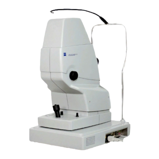
- Page 8 lite VISUCAM - Unit Notes on servicing: Always disconnect the power plug before opening the unit. After servicing, check all functions and, if necessary, the electrical safety of the unit. System overview 1 Cap of fixation light 2 Fixation light 3 Headrest with chinrest 4 Monitor 5 USB Flash Drive (Option)
- Page 9 Overview of functions Camera head Instrument base Stepper Brightness Barrier filter drive Opto-coupler Release Stepper Programming Exciter filter drive Halogen- Opto-coupler Temperatur- bulb sensor Illumination white Control of lite Shutter VISUCAM ϑ Illumination IR +12V Finder camera IR Stepper Camera change Signals Lamp control +12V La...
- Page 10 Help for troubleshooting Questions about mechanical problems Can the camera head be swiveled all the way to the right and left? • lite Can the VISUCAM fundus camera be easily moved and locked on the base within the • entire working range? Is the ophthalmoscope lens clean? •...
- Page 11 lite VISUCAM - Component Service Note: Easy-to-exchange components are not described in detail. Replacing the blinking diode of the fixation light Screw out the blinking diode (1) from its • socket(2). Screw the new blinking diode into the socket. • 1 Blink diode Check whether it is properly functioning.
- Page 12 Separating the camera head from the instrument base Open the camera head • (see: Opening and closing the camera head ). Disconnect the cable for the camera head X14, • X20 from the connector panel. Disconnect the 2 cables leading to the •...
- Page 13 Replacing the complete lamp housing Open the camera head (see: Opening • and closing the camera head ) . Remove the light guide from the top. • Guide slot lite Disconnect 2 cables to VISUCAM • inside cover control PCB. Light guide Remove various cable mounts on the lamp •...
- Page 14 Replacing the fan cooling the lamp housing Note: Fan blows outward. Observe markings on the fan! • Open the camera head (see: Opening and closing the camera head ) . Disconnect the fan cable from X45 on the lamp • control PCB. Screw off the defective fan.
- Page 15 Replacing the light guide Open the camera head (see: Opening and • Securing screw closing the camera head ) . Loosen the upper mount of the light guide • and push the light guide through the hole. Press out the light guide from the clip. •...
- Page 16 Replacing the stepper motor of the exciter filter assembly Stepper Disconnect the stepper motor cable • X8 from the control PCB and remove the cable mounts. • Screw out 2 fastening screws and remove the stepper motor. Opto-coupler Replace the stepper motor by a new •...
- Page 17 Barrier filter assembly Installing / removing the barrier filter assembly Open the camera head (see: Opening • and closing the camera head ) . • Loosen the lamp housing and move it slightly to the side. (See also: Replacing the complete lamp housing ...
- Page 18 Checking the barrier filter drive The function of the stepper motor and opto-coupler can be checked using the service software. • Start the service software (see "Opening the Test Tools program" ) . Select the "step motors" tab. • Select the "barrier" tab. •...
- Page 19 Checking and adjusting the image position of the finder camera Camera Field is max. 768 x 576 pics. Maximum possible settings are: 768 ≤ 576 ≤ b (y) Finder camera a (x) Illuminated ring b > image ↑ b < image ↓ a >...
- Page 20 Camera module B/W camera color camera Replacing the cameras Housing edge Open the camera head (see: Opening • and closing the camera head) • Remove the cable connections. Screw out 3 fastening screws and • remove the camera module. Insert the new module and align it with •...
- Page 21 Adjusting the horizontal image positions of the cameras. Note: The vertical image positions of the cameras are adjusted during the installation of the camera modules by upward and downward shifting along the housing edge. First, the image position of B/W camera sensor is checked and adjusted. •...
- Page 22 lite Replacing the VISUCAM control PCB Note: When exchanging the control PCB, re-enter and save the serial number of the instrument. Also enter and save the instrument type (see Data input fields). Open the camera head (see: Opening • and closing the camera head ) . •...
- Page 23 Opening and closing the control base • Removing the camera head including instrument base. - Disconnect the cable for the camera head. - Loosen the screws in the toothed rack. (2.5mm hex socket head) - Push out the camera head including instrument base to one side.
- Page 24 Replacing the headrest Remove the fixation lamp including the blinking • diode. Loosen the locking screws for the headrest. • Open the base (see: Opening and closing the • control base). Disconnect the cable for the f ixation lamp from X7 •...
- Page 25 Components of the control base GIF instrument interface PS2 Interface Mouse, Keyboardr Med PIII Motherboard Inductive approximation switch +5V, +12V 12VDC fan power supply Line module Hard disk Connection field ...
- Page 26 Exchanging Motherboard MEDP3 Note: To be able to exchange motherboard MEDP3, you first have to remove instrument interface GIF. Motherboard connectors Battery Note: Do not fix the motherboard here with a screw! Hard disk CD-ROM / burner Power supply VGA Display User interface Con.
- Page 27 System settings and work with internal programs Note: The system settings are only accessible to authorized service staff and may only be changed by this staff. The access to the system settings is protected by a password. All system settings have been adjusted ex factory as required in the country of destination.
- Page 28 Keyboard 2 menus are available for defining the settings for the keyboard. In the Speed menu, you can change the mode of operation. In the Language menu, you can adapt the regional settings to the keyboard used. Printer Via this selection, you can access the printer menu.
- Page 29 Network In the Network menu, you can adjust the settings for the network connection. The Configuration window shows the protocols used. In the Identification window, you can enter the computer name assigned by the network administrator (e. g. ZO01Q73J) and the workgroup or domain used (e. g. DEOKO). You can lite also enter a name for the unit connected (e.g.
- Page 30 If you have selected the logon to a domain, after restart the system asks you for your login data of the domain server (zeiss). This data you get from the domain administrator. Note: If the program asks for new drivers you can find drivers in...
- Page 31 Date / Time In the Date/Time Properties menu you can change the time currently set. The time zone can be adapted to the current location. Regional settings In the Regional Settings menu, you can set the language zones. In the Date menu you can set the date. lite Service Instructions VISUCAM Issue: 22.09.2003...
- Page 32 Opening the Windows Explorer program lite VISUCAM is on and in the patient or image ⇒ ⇒ ⇒ ⇒ capture mode. Click the ? in the program bar. • The window with Help Topics and Info opens . ⇒ ⇒ ⇒...
- Page 33 About window The About window contains the actual information about the installed software version, Drivers and t he inserted serial number. Opening the Test Tools program lite VISUCAM is running in the patient or image ⇒ ⇒ ⇒ ⇒ capture mode. Click the in the program bar.
- Page 34 Test and adjustment of mechanical and electrical functions Testing focus drive Test Focus drive for +25dpt Focus the illumination ring to the first area by moving the • lite VISUCAM camera by hand. You should see the structure off the light guide inside the illuminated ring.
- Page 35 Data input fields Start the service software (see "Opening • the Test Tools program" ) . Select the data tab. • Driver information field type HW instrument type selection. DateEE EEPOM programming date. Serial Nr . entry of the serial number. Date VCGIF Grabber driver date.
- Page 36 Input and output signals of the electronic system Start the service software (see "Opening the Test Tools program" ) . • The in / out tab is displayed. • By clicking on the relevant function, ⇒ ⇒ ⇒ ⇒ you can check the function or switch it ON and OFF.
- Page 37 Measuring the operating voltages Input voltage of the power supply unit (X4) +12V +12V Voltage supplied to the instrument interface (GIF) Voltage supplied to the motherboard +12V Output voltage of the power supply unit +12V +5V (red) +12V (yellow) 0V (black) Voltages present at Interface GIF PCB X4 Sensor left right movement...
- Page 39 lite Software VISUCAM Folder Database The Database folder is on drive D: (partition2) and contains: the Visucam.mdb database, • the Image folder for all stored images, • the Sequences folder for the video streams • the TNI`s folder for all thumbnails. • Folder Images The folder Images contains all images (black and white and color) in BMP format.
- Page 40 VISUCAM Save and Update folder In the Save folder the files Main.ini and visucam.mdb are saved as the last correct files during start up. The copies of this files are stored every times if the system is starting up. In the Update folder there are temporarily data during software update. Normally empty! VISUCAM Installs folder A lot of different drivers are placed in this installs folder.
- Page 41 System check Mechanical check Check that the camera head can be swiveled all the way from the left to the right..... • lite Check that VISUCAM fundus camera be easily moved and securely locked on the base • ...
Need help?
Do you have a question about the VISUCAM lite and is the answer not in the manual?
Questions and answers