HFCL Ion4xi User Manual
Indoor & outdoor access point
Hide thumbs
Also See for Ion4xi:
- Quick start manual (15 pages) ,
- Quick start manual (14 pages) ,
- Quick start manual (14 pages)

Related Manuals for HFCL Ion4xi

Summary of Contents for HFCL Ion4xi
- Page 1 User Manual (GUI) Indoor & Outdoor Access Point Wi-Fi 6 Ion4xi/ ion4x/ion4xe Software Version Release Date March, 2021...
- Page 2 Copyright Notice This document is copyright of HFCL Limited, All Rights Reserved. No part of this document, in whole or in part, may be used, reproduced, stored in a retrieval system or transmitted, in any form, or by any means, electronic or otherwise, including photocopying, reprinting, or recording, for any purpose, without the express written permission of HFCL Limited.
- Page 3 Wi-Fi 6 2x2:2 User Manual Rev: A0-00 Revision History Date Rev No. Description 10-03-2021 A0-00 Initial Draft Himankush CONFIDENTIAL...
-
Page 4: Table Of Contents
Wi-Fi 6 2x2:2 User Manual Rev: A0-00 Table of Contents ABOUT THIS DOCUMENT ......................... 11 ............................11 URPOSE ........................11 NTENDED UDIENCE ......................11 OCUMENT ONVENTIONS ......................12 ERMS AND BBREVIATIONS PRODUCT OVERVIEW ........................15 FEDERAL COMMUNICATION COMMISSION CERTIFIED ............... 15 2:2 I .................. - Page 5 Wi-Fi 6 2x2:2 User Manual Rev: A0-00 ......................42 ACKUP LASH IRMWARE 9.4.1 Generate Backup ........................ 42 9.4.2 Upload configuration or backup ..................43 9.4.3 Upgrade firmware ....................... 44 ............................46 EBOOT ........................... 47 ACTORY ESET ........................ 48 YSTEM LOG SETTINGS NETWORK INTERFACES OF THICK AP ...................50 10.1 AP ..........
- Page 6 Wi-Fi 6 2x2:2 User Manual Rev: A0-00 LOGOUT ............................89 INSTALLATION SETUP ........................90 16.1 2:2 I ) ......90 OUNTING OF NDOOR CCESS OINT ALL AND EILING 16.2 2:2 O ) ......94 OUNTING OF UTDOOR CCESS OINT OLE AND 16.2.1 2x2 outdoor AP mounting to the Pole ................
- Page 7 Wi-Fi 6 2x2:2 User Manual Rev: A0-00 List of Figures Figure 1: Dual Band 2x2:2 Indoor Access Point - Specifications & Highlights-1............ 16 Figure 2: Dual Band 2x2:2 Indoor Access Point - Specifications & Highlights-2........... 17 Figure 3: Dual Band 2x2:2 Outdoor Access Point - Specifications & Highlights-1 ..........18 Figure 4: Dual Band 2x2:2 Outdoor Access Point - Specifications &...
- Page 8 Wi-Fi 6 2x2:2 User Manual Rev: A0-00 Figure 36: Basic overview of the advanced radio parameters (2.4 GHz and 5 GHz) configuration screen ..60 Figure 37: Basic overview of the screen to configure general SSID parameters ..........62 Figure 38: Basic overview of the screen to configure wireless security parameters of SSID ......64 Figure 39: Basic overview of the screen to configure wireless security parameters of SSID (RADIUS) ....
- Page 9 Wi-Fi 6 2x2:2 User Manual Rev: A0-00 List of Tables Table 1: List of information displayed in side view of the indoor AP ..............22 Table 2: List of information displayed in top side view of the indoor AP .............. 24 Table 3: List of information displayed in front/side view of the outdoor AP ............
- Page 10 Wi-Fi 6 2x2:2 User Manual Rev: A0-00 Table 37: List of actions to create, edit, or delete a Wi-Fi schedule ..............79 Table 38: List of actions to view schedule job screen ................... 80 Table 39: List of actions to view real-time load graphs ..................81 Table 40: List of actions to view real-time traffic graphs ..................
-
Page 11: About This Document
1.2 Intended Audience The intended audiences for this document are: Network Administrators System Administrators Product managers System Integration and Verification team at HFCL Limited. 1.3 Document Conventions The different conventions used in this document are explained in the following table: Convention Description Note provides information about important features or instructions. -
Page 12: Terms And Abbreviations
Wi-Fi 6 2x2:2 User Manual Rev: A0-00 1.4 Terms and Abbreviations The different terms and abbreviations used in this document are explained in the following table: Terms and Abbreviations Terms/Abbreviation Expansion Access Point Bluetooth Low Energy Command-Line Interface Class Of Service Central Processing Unit DHCP Dynamic Host Configuration Protocol... - Page 13 Wi-Fi 6 2x2:2 User Manual Rev: A0-00 LMAC Lower Media Access Control Media Access Control MBPS Megabits Per Second Modulation And Coding Scheme MIMO Multiple-Input And Multiple-Output MPEG Moving Picture Experts Group Maximum Transmission Unit Network Time Protocol On Screen Display P2MP Point-To-Multipoint Point-To-Point...
- Page 14 Wi-Fi 6 2x2:2 User Manual Rev: A0-00 User Id Unshielded Twisted Pair Virtual Access Point Video Graphic Adapter VLAN Virtual Local Area Network Wide Area Network Wireless Distribution System WIDS Wireless Intrusion Detection System Wireless Lan Controller Wi-Fi Protected Access CONFIDENTIAL...
-
Page 15: Product Overview
Thank you for choosing the IO Access Point (AP). IO Access Points are oriented to next generation high-speed wireless access. The Access Point Configuration is controlled through GUI. Following are the variants of IO product family: Dual Band 2x2:2 Indoor Access Point (ion4xi). Dual Band 2x2:2 Outdoor Access Point (ion4x/ion4xe). Federal Communication Commission Certified These equipment are tested and found to comply with the limits for a Class B digital device, pursuant to Part 15 of the FCC Rules. -
Page 16: Dual Band 2 X 2:2 Indoor Access Point
Wi-Fi 6 2x2:2 User Manual Rev: A0-00 3.1 Dual Band 2x2:2 Indoor Access Point Technical specifications of this variant are given below: Figure 1: Dual Band 2x2:2 Indoor Access Point - Specifications & Highlights-1 CONFIDENTIAL... -
Page 17: Figure 2: Dual Band 2X2:2 Indoor Access Point - Specifications & Highlights-2
Wi-Fi 6 2x2:2 User Manual Rev: A0-00 Figure 2: Dual Band 2x2:2 Indoor Access Point - Specifications & Highlights-2 CONFIDENTIAL... -
Page 18: Ion 4 Xe )
Wi-Fi 6 2x2:2 User Manual Rev: A0-00 3.2 Dual Band 2x2:2 Outdoor Access Point (ion4x/ion4xe) The Dual Band 2x2:2 outdoor Access Point has two factory fitted variants: one with integrated antennas (ion4x) and the other with connectors for external antennas (ion4xe). Technical specifications are given below: Figure 3: Dual Band 2x2:2 Outdoor Access Point - Specifications &... -
Page 19: Figure 4: Dual Band 2X2:2 Outdoor Access Point - Specifications & Highlights-2
Wi-Fi 6 2x2:2 User Manual Rev: A0-00 Figure 4: Dual Band 2x2:2 Outdoor Access Point - Specifications & Highlights-2 CONFIDENTIAL... -
Page 20: Hardware Setup
Wi-Fi 6 2x2:2 User Manual Rev: A0-00 Hardware Setup 4.1 System Requirements Before installing the access point, make sure that your system includes the following: 10/100/1000 Mbps local area network device such as a hub or switch. The Category 5 UTP straight-through Ethernet cable with RJ-45 connector included in the package, or one like it. -
Page 21: Ion 4 Xe Variants Of This Product
Wi-Fi 6 2x2:2 User Manual Rev: A0-00 4.2 Packaging Content – For ion4xi/ion4x/ion4xe variants of this product Your box contains the following items: User can choose any of the Access Point model mentioned below: Dual Band 2x2:2 Indoor Access Point (ion4xi). -
Page 22: Getting To Know The Io Access Point
Wi-Fi 6 2x2:2 User Manual Rev: A0-00 Getting to Know the IO Access Point 5.1 Dual Band 2x2:2 Indoor Access Point 5.1.1 Back / Side View A basic overview of the back/side view of the indoor AP is given below: Figure 5: Side view of the indoor AP Information displayed in the above figure is detailed in the table below: Table 1: List of information displayed in side view of the indoor AP... -
Page 23: Top / Side View
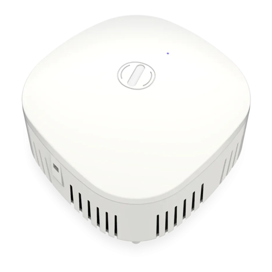
Wi-Fi 6 2x2:2 User Manual Rev: A0-00 Callout Name Description Vent Transfers the heat in the ambient This helps in the attachment of mounting bracket and Mounting Slot indoor AP in case of wall and ceiling mounting 5.1.2 Top / Side View A basic overview of the top/side view of the indoor AP is given below: Figure 6: Top Side view of the indoor AP CONFIDENTIAL... -
Page 24: Table 2: List Of Information Displayed In Top Side View Of The Indoor Ap
Wi-Fi 6 2x2:2 User Manual Rev: A0-00 Information displayed in the above figure is detailed in the table below: Table 2: List of information displayed in top side view of the indoor AP Callout Name Description This LED glows in Green color to notify the user that the 2.4GHz radio is active This LED glows in Blue color to notify the user that the Status LED... -
Page 25: Dual Band
Wi-Fi 6 2x2:2 User Manual Rev: A0-00 5.2 Dual Band 2x2:2 Outdoor Access Point 5.2.1 Front / Side View A basic overview of the front/side view of the outdoor AP is given below: Figure 7: Front/side view of the outdoor AP (ion4x) Information displayed in the above figure is detailed in the table below: Table 3: List of information displayed in front/side view of the outdoor AP Callout... -
Page 26: Back View
Wi-Fi 6 2x2:2 User Manual Rev: A0-00 Callout Name Description Used for powering up the device via PoE adaptor. The LAN + PoE Port same port carries the data Kensington Lock This slot is provided for the Kensington Lock 5.3 Back View Back side overview of the outdoor AP is given below: Figure 8: Back view of the outdoor AP (ion4xe) Information displayed in the above figure is detailed in the table below:... - Page 27 Wi-Fi 6 2x2:2 User Manual Rev: A0-00 Callout Name Description Total 2 n-type antenna connectors or 2 SMA connectors External antenna are available for ion4xe variant of 2x2:2 outdoor AP. connectors These connectors are not available in ion4x variant, as the variant has integrated antennas Kensington Lock This slot is provided for the Kensington Lock...
-
Page 28: Initial Setup
Wi-Fi 6 2x2:2 User Manual Rev: A0-00 Initial Setup Observe the following safety precautions and avoid damage to the access point: Do not power the device during installation. Do not subject the device to high temperatures. Keep away from high voltage cables. Disconnect the device before cleaning it. -
Page 29: Dual Band
Wi-Fi 6 2x2:2 User Manual Rev: A0-00 6.1 Dual Band 2x2:2 Indoor Access Point Power up the device using PoE Adaptor or DC Adaptor as shown below: Figure 9: Power up the device using PoE adaptor Figure 10: Power up the device using DC adaptor CONFIDENTIAL... -
Page 30: Connect To The Indoor Access Point
Wi-Fi 6 2x2:2 User Manual Rev: A0-00 6.1.1 Connect to the Indoor Access Point Follow the steps mentioned below and connect to the indoor AP through GUI: Configure a computer with a 1-domain static IP address e.g. 192.168.1.10 and a subnet mask of 255.255.255.0. -
Page 31: Dual Band
Wi-Fi 6 2x2:2 User Manual Rev: A0-00 6.2 Dual Band 2x2:2 Outdoor Access Point Power up the device using PoE Adaptor as shown below: Figure 12: Power up the device using PoE adaptor CONFIDENTIAL... -
Page 32: Connect To The Outdoor Access Point
Wi-Fi 6 2x2:2 User Manual Rev: A0-00 6.2.1 Connect to the Outdoor Access Point Follow the steps mentioned below and connect to the outdoor AP through GUI: Configure a computer with a 1-domain static IP address e.g. 192.168.1.1 and a subnet mask of 255.255.255.0. -
Page 33: Connect To The Thick Access Point And Log In
Wi-Fi 6 2x2:2 User Manual Rev: A0-00 Connect to the Thick Access Point and Log In You can connect to the access point’s web management interface to view or change its LAN and wireless access settings. Refer the procedure mention in “Connect to the Indoor Access Point” and “Connect to the Outdoor Access Point”... -
Page 34: Status Overview Screen
Wi-Fi 6 2x2:2 User Manual Rev: A0-00 Status overview screen The screen provides the status overview of: System summary System feature Software Hardware 8.1 System summary A basic layout of the system summary is given below: Figure 15: Basic layout of the system summary screen Follow the steps given below to view the system summary: Table 6: List of information displayed in the system summary Callout... - Page 35 Wi-Fi 6 2x2:2 User Manual Rev: A0-00 Callout Name Description Displays the model number of the product. The same is Model configured with the factory settings of the device and reflects in this section on system boot up Product Name Displays the name of the product Displays the current acting mode of the AP (Thick mode Current Mode...
-
Page 36: System Software
Wi-Fi 6 2x2:2 User Manual Rev: A0-00 8.2 System software A basic layout of the system software is given below: Figure 16: Basic layout of the system software screen Follow the steps given below to view the system software information: Table 7: List of information displayed in the system software screen Callout Name... -
Page 37: System Hardware
Wi-Fi 6 2x2:2 User Manual Rev: A0-00 8.3 System hardware A basic layout of the system hardware is given below: Figure 17: Basic layout of the system hardware screen Follow the steps given below to view the system hardware information: Table 8: List of information displayed in the system hardware screen Callout Name... -
Page 38: System Wireless
Wi-Fi 6 2x2:2 User Manual Rev: A0-00 8.4 System Wireless A basic layout of the system wireless is given below: Figure 18: Basic layout of the system wireless screen Follow the steps given below to view the system wireless summary: Table 9: List of information displayed in the system wireless screen Callout Name... -
Page 39: System Maintenance Screen
Wi-Fi 6 2x2:2 User Manual Rev: A0-00 System maintenance screen The maintenance activities of the respective access point are executed from this screen. The list of options available for the user is given below: System general and log settings Admin password configuration Backup/Flash Firmware Reboot Factory Reset... - Page 40 Wi-Fi 6 2x2:2 User Manual Rev: A0-00 Callout Name Description Select the respective “Timezone” from the dropdown list. It represents the region of the globe that observes a uniform standard time for legal, commercial, and social Time Zone purposes. The date and time of the respective timezone will be reflected in the system summary of status overview screen.
-
Page 41: Set Password For Thick Ap
Wi-Fi 6 2x2:2 User Manual Rev: A0-00 9.3 Set Password for thick AP This screen provides the user with options to change the default password for respective thick access point. The default username is “root” and the default admin password is “root”. A basic overview of the screen is given below: Figure 20: Basic overview of the system admin password configuration screen for thick AP Follow the steps given below and configure the system admin password for the thick AP:... -
Page 42: Backup/Flash Firmware
Wi-Fi 6 2x2:2 User Manual Rev: A0-00 9.4 Backup/Flash Firmware Downloading the configuration files at an external drive location and updating the configuration files from an external file is a common feature. It helps the user to keep a backup of different configuration files and even makes it easier to apply the same in multiple devices. -
Page 43: Upload Configuration Or Backup
Wi-Fi 6 2x2:2 User Manual Rev: A0-00 9.4.2 Upload configuration or backup Use an existing valid configuration file or device backup file and change the device parameters respectively from this screen. The user can apply similar configuration to multiple devices or can apply different type of configurations to various set of devices with minimal of the effort. -
Page 44: Upgrade Firmware
Wi-Fi 6 2x2:2 User Manual Rev: A0-00 9.4.3 Upgrade firmware The firmware is stored in the flash memory and can be updated with new versions to include new features or to modify the existing one. This AP has two partitions. The firmware version is always uploaded in the alternate partition to keep the current firmware image restored which is located in the current partition of access point. - Page 45 Wi-Fi 6 2x2:2 User Manual Rev: A0-00 Callout Name Description the same while updating the firmware of the device with a new version. Click on “Browse” option. A popup window will appear on the screen. Go to the respective folder of software file Browse/Image and select the sysupgrade-compatible image to replace the running firmware.
-
Page 46: Reboot
Wi-Fi 6 2x2:2 User Manual Rev: A0-00 9.5 Reboot Reboot restarts the device with existing configuration. We can change the firmware when the device is rebooted with different partitions. Based on the selected partition, the corresponding firmware will be loaded into the device as working firmware A basic overview of the Reboot screen is given below: Figure 25: Basic overview of the reboot screen... -
Page 47: Factory Reset
Wi-Fi 6 2x2:2 User Manual Rev: A0-00 9.6 Factory Reset The device has factory assigned settings and configurations on deployment. The user can set the device to the same from this screen. The device will be configured back to factory settings and the existing settings and configurations will be discarded. -
Page 48: System Log Settings
Wi-Fi 6 2x2:2 User Manual Rev: A0-00 9.7 System log settings If user wants to see the back-end logs or if user faces any issue, logs relevant to the AP’s application software are populated in the “Diagnostic/System Log” screen for monitoring purpose. The same can be uploaded to an external server and the configuration for the same is performed in this screen. - Page 49 Wi-Fi 6 2x2:2 User Manual Rev: A0-00 Callout Name Description debug to emergency will be logged and if “Notice” is selected, logs from Notice to Emergency will be logged Click on “Save & Apply” to save the system admin password configuration or click “Reset” to configure the same again.
-
Page 50: Network Interfaces Of Thick Ap
Wi-Fi 6 2x2:2 User Manual Rev: A0-00 10 Network interfaces of thick AP A basic overview of the network interface screen for thick AP is given below: Figure 28: Basic overview of the interface configuration screen for thick AP Follow the steps given below to view/edit the interface configuration of thick AP: Table 18: List of actions to view/edit the network configuration of thick AP Callout Name... -
Page 51: General Network Interface Setup Configuration For Thick Ap
Wi-Fi 6 2x2:2 User Manual Rev: A0-00 10.1 General Network interface setup configuration for thick AP The default IP address of the access point is set to 192.168.1.1. The user can change the current static IP address of the device from this screen. DHCP client (DHCP client or DHCPv6 client) option is to get the dynamic IP address from reachable DHCP server in the network. -
Page 52: Static Ip Configuration For Thick Ap
Wi-Fi 6 2x2:2 User Manual Rev: A0-00 10.1.1 Static IP configuration for thick AP The default IP address of the access point is set to 192.168.1.1. User can change the default IP address with an unused IP address. Refer “Figure 29: Basic overview of the network interface setup configuration screen to switch protocol for thick AP”... - Page 53 Wi-Fi 6 2x2:2 User Manual Rev: A0-00 Callout Name Description Enter the “IPv6 address”. Unique address of the IPv6 address Host/Device e.g.2001:11::100 Specify the prefix length for IPv6 address. Specifies the number of bits that belong to network part. The prefix- length specifies a range of devices IPv6 prefix length e.g.
-
Page 54: Dhcpv4 Client Configuration For Thick Ap
Wi-Fi 6 2x2:2 User Manual Rev: A0-00 10.1.2 DHCPv4 client configuration for thick AP If the protocol is set to DHCPv4 client, the device will automatically get the IPv4 address from the DHCP server. Refer “Figure 29: Basic overview of the network interface setup configuration screen to switch protocol for thick AP”... -
Page 55: Dhcpv6 Client Configuration For Thick Ap
Wi-Fi 6 2x2:2 User Manual Rev: A0-00 10.1.3 DHCPv6 client configuration for thick AP If the protocol is set to DHCPv6 client, the device will automatically get the IPv6 address from the DHCP server. Refer “Figure 29: Basic overview of the network interface setup configuration screen to switch protocol for thick AP”... -
Page 56: Network/Wireless/Radio And Ssid Configuration Of Thick Ap
Wi-Fi 6 2x2:2 User Manual Rev: A0-00 10.2 Network/Wireless/Radio and SSID configuration of thick AP The wireless configuration screen of thick AP GUI enables the user to view and configure radio and SSID parameters. Multiple SSID can be added separately for 2.4 and 5 GHz radio. Radio configuration remains same for all SSIDs operating at the respective 2.4 and 5 GHz radio. -
Page 57: Ghz Radio Configuration
Wi-Fi 6 2x2:2 User Manual Rev: A0-00 Callout Name Description Displays the overview of 2.4 GHz radio along with the list 2.4 GHz overview of associated SSIDs as shown in the above figure Add SSID/Radio Click on the “Add” option to configure a new SSID or to Configuration update the radio configuration parameters at 2.4 GHz Click on “Edit”... - Page 58 Wi-Fi 6 2x2:2 User Manual Rev: A0-00 Callout Name Description Select the “Channel Width” from the dropdown list Channel Width (20 MHz/40 MHz/80 MHz) Select the “Channel” from the dropdown list. The device will choose the channel by itself, if “auto” channel is selected.
-
Page 59: Ghz Radio Configuration
Wi-Fi 6 2x2:2 User Manual Rev: A0-00 10.2.2 2.4 GHz radio configuration This screen provides the user with options to configure the 2.4 GHz radio parameters such as channel bandwidth, respective channel or the channel selection process, and the power for the radio signal transmission. -
Page 60: Advanced Radio Configuration (2.4 Ghz And 5 Ghz)
Wi-Fi 6 2x2:2 User Manual Rev: A0-00 10.2.3 Advanced radio configuration (2.4 GHz and 5 GHz) This screen provides the user with options to configure the advanced radio parameters (2.4 GHz and 5 GHz) such as country code and Tx/Rx chain mask. Refer the “Figure 33: Basic overview of the wireless configuration screen for thick AP”... - Page 61 Wi-Fi 6 2x2:2 User Manual Rev: A0-00 Click “Save & Apply” to save the advanced radio parameters (2.4 GHz and 5 GHz) configuration of thick AP or click “Reset” to configure the same again. CONFIDENTIAL...
-
Page 62: Ssid Configuration
Wi-Fi 6 2x2:2 User Manual Rev: A0-00 10.2.4 SSID configuration Refer the “Figure 33: Basic overview of the wireless configuration screen for thick AP” and click on Add SSID/Radio Configuration option (8) for 2.4 GHz or Add SSID/Radio Configuration option (4) for 5 GHz to configure new SSIDs. - Page 63 Wi-Fi 6 2x2:2 User Manual Rev: A0-00 Callout Name Description Enable/Disable SSID broadcast with this option. Once disabled, the SSID will not be available in the search Hide SSID anymore. The user can still associate with the SSID if valid authenticated credentials are provided Click “Save &...
-
Page 64: Ssid/Wireless Security (2.4 Ghz And 5 Ghz)
Wi-Fi 6 2x2:2 User Manual Rev: A0-00 SSID/Wireless security (2.4 GHz and 5 GHz) 10.2.4.2 By default the wireless security is set to “No Encryption”, and few of the other options provided to change the encryption accordingly are as follows: No Encryption: Any device can connect to the network. - Page 65 Wi-Fi 6 2x2:2 User Manual Rev: A0-00 Callout Name Description Enter a unique password for the SSID Click “Save & Apply” to save the wireless security configuration of SSID or click “Reset” to configure the same again. CONFIDENTIAL...
-
Page 66: Figure 39: Basic Overview Of The Screen To Configure Wireless Security Parameters Of Ssid (Radius)
Wi-Fi 6 2x2:2 User Manual Rev: A0-00 RADIUS based Wireless security Encryption 10.2.4.2.2 A basic overview of the screen to configure wireless security parameters of SSID is given below: Figure 39: Basic overview of the screen to configure wireless security parameters of SSID (RADIUS) Follow the steps given below and configure the wireless security parameters of SSID: Table 29: List of actions to configure the wireless security parameters of SSID (RADIUS) Callout... -
Page 67: Ssid/Mac Filter (2.4 Ghz And 5 Ghz)
Wi-Fi 6 2x2:2 User Manual Rev: A0-00 SSID/MAC filter (2.4 GHz and 5 GHz) 10.2.4.3 The user can add multiple MAC addresses with allow and deny policy and the same is mapped with respective SSID. A basic overview of the screen to configure the MAC filter for SSID configuration is given below: Figure 40: Basic overview of the screen to configure the MAC filter for SSID configuration Follow the steps given below and configure the MAC filter for SSID configuration:... -
Page 68: Ssid/Advanced Settings (2.4 Ghz And 5 Ghz)
Wi-Fi 6 2x2:2 User Manual Rev: A0-00 SSID/Advanced settings (2.4 GHz and 5 GHz) 10.2.4.4 A basic overview of the screen to configure the advanced parameters of SSID configuration is given below: Figure 41: Basic overview of the screen to configure the advanced parameters of SSID configuration CONFIDENTIAL... -
Page 69: Table 31: List Of Actions To Configure The Advanced Parameters Of Ssid Configuration
Wi-Fi 6 2x2:2 User Manual Rev: A0-00 Follow the steps given below and configure the advanced parameters of SSID configuration: Table 31: List of actions to configure the advanced parameters of SSID configuration Callout Name Description Advanced Settings Click on “Advanced Settings” option Click on the check box and enable or disable the client Client Isolation isolation feature. - Page 70 Wi-Fi 6 2x2:2 User Manual Rev: A0-00 Callout Name Description Set the ATF scheduling to either “Fair Time Scheduling” ATF Scheduling or “Strict Time Scheduling” Air Time % Set the air time between 10 to 100 TX STBC Enable/Disable the Tx space time block coding RXSTBC Enable/Disable the Rx space time block coding Number of Spatial Streams...
-
Page 71: Network/Easymesh Configuration Of Thick Ap
Wi-Fi 6 2x2:2 User Manual Rev: A0-00 10.3 Network/EasyMesh configuration of thick AP A wireless mesh network serves as a network of radio nodes organized in a mesh topology. All APs participating in mesh topology does not need to have a wired connection for backhaul connectivity and only one root AP serves that purpose. - Page 72 Wi-Fi 6 2x2:2 User Manual Rev: A0-00 Callout Name Description AP/Agent AP). If the AP mode is set to “Controller AP”, make sure that the AP is connected to the wired network. Agent AP automatically connects to the controller AP if they are of the same vendor Click on this option to connect with an AP which belong to any other vendor.
-
Page 73: Dhcp Server Configuration Of Thick Ap
Wi-Fi 6 2x2:2 User Manual Rev: A0-00 10.4 DHCP server configuration of thick AP The AP itself can act as a DHCP service provider for the connected clients and configuration for the same is executed from this screen. A basic overview of the screen to enable thick AP as DHCP server (IPv4) is given below: Figure 43: Basic overview of the screen to enable thick AP as DHCP server (IPv4) Follow the steps given below to enable thick AP as DHCP server (IPv4):... -
Page 74: Figure 44: Basic Overview Of The Screen To Enable Thick Ap As Dhcp Server (Ipv6)
Wi-Fi 6 2x2:2 User Manual Rev: A0-00 Callout Name Description Enter a value to set a limit on the lease time. New addresses will be assigned to the associated clients Lease Time once the previous lease has expired as per the specified lease time Click “Save &... - Page 75 Wi-Fi 6 2x2:2 User Manual Rev: A0-00 Callout Name Description e.g. IPv6 prefix length = 64 means range of IP addresses between 2001:0DB8:ABCD:0012:0000:0000:0000:0000 and 2001:0DB8:ABCD:0012:FFFF:FFFF:FFFF:FFFF. Enter the “IPv6 gateway”. Gateway address is given to IPv6 Gateway reach other network device e.g.2001:11::1 Enter the IP address for DNS server.
-
Page 76: Static Routes
Wi-Fi 6 2x2:2 User Manual Rev: A0-00 10.5 Static Routes User can configure static routes and redirect packets to the destination network. A static route is a pre- determined pathway that a packet must travel to reach a specific host or network. A basic overview of the static route configuration screen for thick AP is given below: Figure 45: Basic overview of the static route configuration screen for thick AP Follow the steps given below for static route configuration of thick AP:... - Page 77 Wi-Fi 6 2x2:2 User Manual Rev: A0-00 Callout Name Description Enter the IP address of the gateway in IPv4 format through which the destination host or network can be reached. If the current AP is being used to connect IPv4-Gateway network with the Internet, then your gateway IP is the AP's IP address.
-
Page 78: Wi-Fi Schedule
Wi-Fi 6 2x2:2 User Manual Rev: A0-00 11 Wi-Fi Schedule This screen is provided with options to create, edit, or delete a Wi-Fi schedule. A basic overview of the screen is given below: Figure 46: Basic overview of the Wi-Fi schedule screen Follow the steps given below to view Wi-Fi schedule screen: Table 36: List of actions to view Wi-Fi schedule screen Callout... -
Page 79: Figure 47: Basic Overview Of The Wi-Fi Schedule Screen
Wi-Fi 6 2x2:2 User Manual Rev: A0-00 A basic overview of the schedule parameters are given below: Figure 47: Basic overview of the Wi-Fi schedule screen Follow the steps given below to create, edit, or delete a Wi-Fi schedule: Table 37: List of actions to create, edit, or delete a Wi-Fi schedule Callout Name Description... -
Page 80: View Schedule Job
Wi-Fi 6 2x2:2 User Manual Rev: A0-00 12 View Schedule Job All Wi-Fi schedules are listed in this screen. A basic overview of the schedule job screen is given below: Figure 48: Basic overview of the view schedule job screen Follow the steps given below to view schedule job screen: Table 38: List of actions to view schedule job screen Callout... -
Page 81: Statistics
Wi-Fi 6 2x2:2 User Manual Rev: A0-00 13 Statistics 13.1 Real-time Graphs/Load The real time load graph shows the CPU load of last 3 min and the graph is refreshed at every 3 sec interval. In addition to the displayed graph the user can find the average and the peak CPU load values of the respective AP. -
Page 82: Real-Time Graphs/Traffic
Wi-Fi 6 2x2:2 User Manual Rev: A0-00 13.2 Real-time Graphs/Traffic The real time load/traffic graph shows the CPU load of last 3 min and the graph is refreshed at every 3 sec interval. In addition to the displayed graph the user can find the inbound and outbound traffic of the associated SSIDs, bridge interface, and Ethernet interfaces along with average and the peak traffic values. -
Page 83: Diagnostics
Wi-Fi 6 2x2:2 User Manual Rev: A0-00 14 Diagnostics Following are the diagnostic features provided in thick AP GUI. 14.1 Routes This screen is provided to view the active routes on the system. A basic overview of the screen to view the active routes is given below: Figure 51: Basic overview of the screen to view the active routes Follow the steps given below to view the active routes on the system:... -
Page 84: System Log
Wi-Fi 6 2x2:2 User Manual Rev: A0-00 14.2 System Log This screen is provided to view the AP logs if the user faces any issue or wants to view the back-end logs. Only new logs are shown in this screen. However, old logs are stored in the database but will not be shown in this screen. -
Page 85: Kernel Log
Wi-Fi 6 2x2:2 User Manual Rev: A0-00 14.3 Kernel Log Boot logs, driver logs, Wi-Fi and firmware related logs are listed in this screen. Kernel log will be accumulated from boot up time till shut down time of the respective AP. A basic overview of the Kernel Log screen is given below: Figure 53: Basic overview of the Kernel Log screen Follow the steps given below to view the Kernel log of the AP:... -
Page 86: Diagnostic Tools
Wi-Fi 6 2x2:2 User Manual Rev: A0-00 14.5 Diagnostic Tools As part of diagnostics, the user can perform the following activities: The user can check if the link connection is established or not with “Ping” option The user can trace the route of the established link with “Traceroute” option 14.5.1 Check the network connection/status This utility is used to test connectivity between the respective AP and another device on the network. -
Page 87: Check The Route Of The Established Network Connection
Wi-Fi 6 2x2:2 User Manual Rev: A0-00 14.5.2 Check the route of the established network connection This utility will display all the routers present between the destination IP address and this AP. Up to 30 “hops” (intermediate routers) between the AP and the destination can be monitored. A basic overview of the Diagnostic Tools screen to check the route of established connection is given below: Figure 55: Basic overview of the diagnostics tool screen to check the route of established connection Follow the steps given below to check the route of established connection:... -
Page 88: Associated Stations
Wi-Fi 6 2x2:2 User Manual Rev: A0-00 14.6 Associated Stations The list of connected clients along with the relevant information in respective information columns is populated in this screen. A basic overview of the screen to show connected clients is given below: Figure 56: Basic overview of the screen to show connected clients Follow the steps given below to view connected clients: Table 46: List of actions to view connected clients... -
Page 89: Logout
Wi-Fi 6 2x2:2 User Manual Rev: A0-00 15 Logout Click on the logout option to terminate the user session. CONFIDENTIAL... -
Page 90: Installation Setup
Wi-Fi 6 2x2:2 User Manual Rev: A0-00 16 Installation Setup IO Indoor AP can be mounted onto the wall or ceiling, whereas the outdoor AP can be wall-mounted or pole mounted. Perform the steps discussed in below sections for the appropriate installation of indoor and outdoor APs: 16.1 Mounting of Dual Band 2x2:2 Indoor Access Point (Wall and Ceiling) Refer the image below for attaching parts required for wall/ceiling mounting of AP:... -
Page 91: Figure 58: Attaching Bracket On To The Wall Or Ceiling For Indoor Ap
Wi-Fi 6 2x2:2 User Manual Rev: A0-00 Use the supplied screws and mount the attaching bracket on to the wall or ceiling as shown below: Figure 58: Attaching bracket on to the wall or ceiling for indoor AP Note: Make sure that the attaching bracket is tightly installed before mounting the access point on the wall or ceiling. -
Page 92: Figure 59: Wall/Ceiling Mounted Attaching Bracket
Wi-Fi 6 2x2:2 User Manual Rev: A0-00 Refer the image below for wall mounted attaching bracket: Figure 59: Wall/ceiling mounted attaching bracket Align the mounting slots of indoor AP and attaching bracket as shown below: Figure 60: Alignment of mounting bracket with indoor AP CONFIDENTIAL... -
Page 93: Figure 61: Backside View Of Attaching Bracket With Indoor Ap
Wi-Fi 6 2x2:2 User Manual Rev: A0-00 Refer the image below for backside view of wall/ceiling mounted AP: Figure 61: Backside view of attaching bracket with indoor AP The wall or ceiling mounted AP is shown below: Figure 62: Wall/ceiling mounted indoor AP Slightly push and slide the access point out from the mounting slots of attaching bracket to unmount the AP. -
Page 94: Mounting Of Dual Band 2X2:2 Outdoor Access Point (Pole And Wall)
Wi-Fi 6 2x2:2 User Manual Rev: A0-00 16.2 Mounting of Dual Band 2x2:2 Outdoor Access Point (Pole and Wall) 2x2 outdoor AP has four holes on its back side for the attachment of mounting bracket, as shown in “Figure 8: Back view of the outdoor AP”... -
Page 95: Figure 64: Mounting Bracket Alignment With The 2X2 Outdoor Ap
Wi-Fi 6 2x2:2 User Manual Rev: A0-00 Final alignment of the mounting bracket with 2x2 outdoor AP is as shown below: Figure 64: Mounting bracket alignment with the 2x2 outdoor AP The mounting instructions of 2x2 outdoor AP is detailed in further sections below. CONFIDENTIAL... -
Page 96: 2X2 Outdoor Ap Mounting To The Pole
Wi-Fi 6 2x2:2 User Manual Rev: A0-00 16.2.1 2x2 outdoor AP mounting to the Pole Follow the steps given below and mount the device onto the pole: Align the bracket mounted AP with pole holder and U-bolt as shown below: Figure 65: Overview of the 2x2 outdoor AP with pole and mounting bracket attaching parts Pass the U-bolt through the cuts of pole holder and mounting bracket. -
Page 97: Figure 66: Final Alignment Of 2X2 Outdoor Ap And Mounting Bracket
Wi-Fi 6 2x2:2 User Manual Rev: A0-00 Figure 66: Final alignment of 2x2 outdoor AP and mounting bracket As shown above, the 2x2 outdoor AP has the freedom of movement along the vertical and horizontal axis. CONFIDENTIAL... -
Page 98: Figure 67: Basic Overview Of Pole Mounted 2X2 Outdoor Ap
Wi-Fi 6 2x2:2 User Manual Rev: A0-00 The final alignment of 2x2 outdoor AP in a pole mounting is shown in the figure below: Figure 67: Basic overview of pole mounted 2x2 outdoor AP CONFIDENTIAL... -
Page 99: 2X2 Outdoor Ap Mounting To The Wall
Wi-Fi 6 2x2:2 User Manual Rev: A0-00 16.2.2 2x2 outdoor AP mounting to the Wall To mount the device onto the wall, foundation bolts and attaching bolts are needed along with the wall mounting bracket. Refer the image given below: Figure 68: Items needed for wall mounting of the device Follow the steps given below and mount the device onto the wall: Take the reference from the printed sheet provided along with the wall mounting bracket and mark... -
Page 100: Figure 69: Basic Overview Of Wall Mounted 2X2 Outdoor Ap
Wi-Fi 6 2x2:2 User Manual Rev: A0-00 Figure 69: Basic overview of wall mounted 2x2 outdoor AP CONFIDENTIAL... -
Page 101: Grounding Of Ap
Wi-Fi 6 2x2:2 User Manual Rev: A0-00 16.3 Grounding of AP The AP should be properly grounded upon installment. The IO’s 2x2 outdoor AP has a grounding position at the back side of the device as shown below: Figure 70: Grounding point of 2x2 outdoor AP A grounding strap can be made from the ring lug terminal of M4 size and a medium length copper wire of suggested gauge AWG-6 (4.1 mm). -
Page 102: Use Cases
Wi-Fi 6 2x2:2 User Manual Rev: A0-00 17 Use Cases A. Indoor Access Point Figure 71: Use Case Diagram of Indoor AP B. Outdoor Access Point Figure 72: Use Case Diagram of Outdoor AP CONFIDENTIAL...
Need help?
Do you have a question about the Ion4xi and is the answer not in the manual?
Questions and answers