Subscribe to Our Youtube Channel
Summary of Contents for Campbell SDM-CD16D
- Page 1 SDM-CD16D 16 Channel Digital Control Port Expansion Module User Guide Issued 15.6.99 © Copyright 1999 Campbell Scientific Ltd.
- Page 3 Note that goods sent air freight are subject to Customs clearance fees which Campbell Scientific will charge to customers. In many cases, these charges are greater than the cost of the repair. Campbell Scientific Ltd,...
-
Page 5: Table Of Contents
1. SDM-CD16D ..................1 2. Equivalent Output Driver Circuit ............2 3. Connection Block Diagrams..............3 4. Use of Terminal Blocks................5 5. Address Selection Switch ............... 6 Tables 1. Datalogger to SDM-CD16D Connections..........4 2. Switch Position and Address ..............5... -
Page 7: Introduction
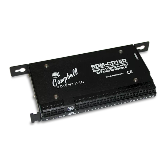
The SDM-CD16D is a synchronously addressed datalogger peripheral. Datalogger control ports 1, 2 and 3 are used to address the SDM-CD16D then clock out the desired state of each of the 16 control ports. Up to sixteen SDM-CD16Ds may be addressed, making it possible to control a maximum of 256 ports from the first three datalogger control ports. -
Page 8: Output Specifications
SDM-CD16D. For some applications it may be convenient to use the datalogger supply to power the SDM-CD16D, as shown in Figure 3. For long-term applications, the lead-acid power supply available with Campbell Scientific dataloggers should be used, allowing the batteries to be float charged. Alkaline batteries are not recommended... -
Page 9: Installation
SDM-CD16D DATALOGGER Connection with External Supply DATALOGGER SDM-CD16D Connection with Datalogger Supply Figure 3 Connection Block Diagrams If the 21X power supply is used to power the SDM-CD16D, all low NOTE level analogue measurements (thermocouples, pyranometers, thermopiles, etc.) must be made differentially. This is a result of slight ground potentials created along the 21X analogue terminal strip when the 12V supply is used to power peripherals. -
Page 10: Controlled Device Connections
Multiple SDM-CD16Ds may be wired in parallel by connecting the datalogger side of one SDM-CD16D to the next. The transient protection of the SDM-CD16D relies on a low resistance path to earth. Ensure that the ground return wire has as low a resistance as possible. -
Page 11: Address Selection Switches
Figure 4 Use of Terminal Blocks 5. Address Selection Switches Each SDM-CD16D can have 1 of 16 addresses. The factory-set address is 00. Table 2 shows switch position and the corresponding address. Figures 1 and 5 shows the position of the switch. Note that you will have to remove the mounting bracket to gain access to this switch. -
Page 12: Datalogger Instructions 104
(0) de-activates the port (sets LO 0V). For example, assuming two repetitions and a starting input location of 33, outputs 1 to 16 of the first SDM-CD16D are set according to input locations 33 to 48, and outputs 1 to 16 of the second... -
Page 13: Theory Of Operation
C2 as a clock line and C1 as a serial data line. The datalogger shifts out a data bit on C1 (LSB first) on the falling edge of the C2 clock. The SDM-CD16D shifts in the C1 data bit on the rising edge of the C2 clock. - Page 14 SDM-CD16D 16 Channel Digital Control Port Expansion Module 10..14 Heat #1..#5 Heater control, greenhouse 1..5 SDM-CD16D Port 1..5 15..19 Cool #1..#5 Cooler control, greenhouse 1..5 SDM-CD16D Port 6..10 20..24 Fan #1..#5 Fan control, greenhouse 1..5 SDM-CD16D Port 11..15 ;{CR10X} *Table 1 Program...
- Page 15 User Guide End heater control logic Start cooler control logic if ‘cooler on’ threshold If (X<=>F) (P89) is exceeded 1: 1 -- X Loc [ Temp_1 2: 3 >= 3: 27.5 then 4: 30 Then Do put a ‘1’ into cooler Z=F (P30) control location 1: 1...
- Page 16 3: 22 Set Flag 2 Low End fan control logic based on time Input locations 10 to 24 are now loaded with a ‘1’ or ‘0’ to set ports on the SDM-CD16D send instructions to the SDM-CD16 / SDM-CD16D (P104)
- Page 17 User Guide 4 Temp_4 10 0 0 5 Temp_5 18 0 0 6 _________ 0 0 0 7 _________ 0 0 0 8 _________ 0 0 0 9 _________ 0 0 0 10 Heat_1 7 3 3 11 Heat_2 11 1 0 12 Heat_3 11 1 0 13 Heat_4...


Need help?
Do you have a question about the SDM-CD16D and is the answer not in the manual?
Questions and answers