Table of Contents
Advertisement
Quick Links
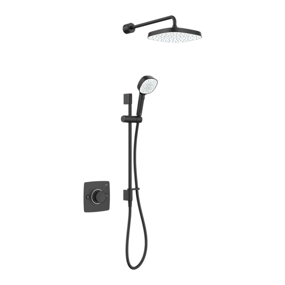
Mira Evoco
Installation and User Guide
Evoco Dual
Evoco Triple
These instructions must be left with the user
Model Name:
Product Code:
Date of Manufacture:
(Please keep these details safe as you will need them when registering your
product guarantee. Your guarantee information is included in this guide.)
Affix Sticker Here
1
For SPARES,
ADVICE or REPAIRS
please call us free
on 0800 001 4040
(UK only)
1478624-W2-A
Advertisement
Table of Contents

Related Manuals for Kohler Mira Evoco Series


Summary of Contents for Kohler Mira Evoco Series
- Page 1 Mira Evoco Installation and User Guide Evoco Dual For SPARES, ADVICE or REPAIRS please call us free on 0800 001 4040 (UK only) Evoco Triple These instructions must be left with the user Model Name: Affix Sticker Here Product Code: Date of Manufacture: (Please keep these details safe as you will need them when registering your product guarantee.
-
Page 2: Safety Information
Ensure that any pipework that could become frozen is properly insulated. DO NOT perform any unspecified modifications to the shower or its accessories. When servicing only use genuine Kohler Mira replacement parts. If the shower is dismantled during installation or servicing then, upon completion, an inspection must be made to ensure all connections are tight and that there are no leaks. - Page 3 7. Children younger than 3 years should not use this shower. Children 3 years to under 8 years should only use this shower under continuous supervision. Children aged 8 years and above and persons with reduced physical, sensory or mental capabilities or lack of experience or knowledge can use the shower if they are given supervision or instruction concerning use of the appliance in a safe way and understand the hazards involved.
-
Page 4: Recommended Usage
Products manufactured by Kohler Mira Ltd are designed to be safe, provided that they are installed, used and maintained in good working order, in accordance with our instructions and recommendations. -
Page 5: Pack Contents
Pack Contents Important! Some parts may differ from the below depending on product purchased. X1 q X2 q X1 q X1 q X4 q X4 q X6 q X1 q X1 q X2 q X1 q X1 q X1 q X1 q X4 q X3 q... - Page 6 Important! Some parts may differ from the below depending on product purchased. X1 q X1 q X1 q X1 q X1 q Push Fit Stop End (suitable for 15mm copper pipe) q Waterproof Tanking Adhesive (see ‘Installation - General’ for details) q X1 q Silicone Sealant q Additional Items Required (Not Supplied)
-
Page 7: Specifications
Specifications Pressures Maximum Static Pressure 1000 kPa (10 bar) Maximum Maintained Pressure 500 kPa (5 bar) Minimum Maintained Pressure 100 kPa (1 bar) (Gas Water Heater) (for optimum performance supplies should be nominally equal) Minimum Maintained Pressure 10 kPa (0.1 bar), (Gravity System) (0.1 bar = 1 Metre head from cold tank base to shower handset outlet) -
Page 8: Suitable Plumbing Installations
Suitable Plumbing Installations The Thermostatic Mixer can be installed with all systems with balanced pressures. Mixed gravity and mains supplies are not recommended. Installation Warning! This product does not allow for reversed inlets and will deliver unstable temperatures if fitted incorrectly. General Installation of the shower must be carried out in accordance with these instructions by qualified, competent personnel. - Page 9 11. Position the shower unit where the controls are at a convenient height for the user. Position the showerhead so that the water sprays in line with the bath or across the opening of a shower cubicle. The installation must not cause the shower hose to be kinked during normal use.
- Page 10 Installation Warning! Isolate the water supplies before installing the shower. Decide on a suitable position for the shower unit and fittings. Overhead Overhead Outlet Pipe Outlet Pipe Bath Bath Filler Filler Shower Shower Fittings Building In Fittings Building In HOT COLD HOT COLD Water Inlets Water Inlets...
- Page 11 Copper pipes into push fit connectors Noggin Mount Noggin Copper Clamp pipes into push fit (x2) connectors Clamp Noggin Mount Rear Fixing Mounting Method Clearance Noggin for outlet Noggin Copper Mount plug or third pipes into outlet push fit connectors 195-200mm Copper pipes into...
- Page 12 Finished Finished Wall Thickness Wall Cutout Wall (e.g. tile and adhesive) Depth ‘X’ Surface Rear 86 - 66mm Mounting 84 - 64mm 82 - 62mm 10mm 80 - 60mm 12mm 78 - 58mm 14mm 76 - 56mm 16mm 74 - 55mm Finished Wall Thickness...
- Page 13 Important! DO NOT remove the cap for Dual Outlet product. Blanking Plugs Blanking Blanking Collet Plug Plugs Evoco Dual Evoco Triple Push and hold the collet before removing the blanking plugs. 36mm Locking COLD Clips Important! Cut the pipe using a pipe cutter only to ensure the seals Insert locking clip here are not damaged when the pipe is inserted.
- Page 14 Overhead Outlet Pipe Bath Filler Shower Fittings Building In HOT COLD Water Inlets Evoco Triple Overhead Outlet Pipe Bath Filler Shower Fittings Building In HOT COLD Water Inlets Evoco Dual Fit the outlet pipework ready for connection to either a right angle connector for a handset, bath (adjustable fitting), or a shower arm for a fixed spray head (rigid fitting).
- Page 15 Flushing the Pipework A flushing cartridge is prefitted into the Building in Box to aid in flushing any dirt or debris from the pipework. Push fit stop end caps are required to test the Building In Box’s inlet and outlet joints for leaks. Cover Push Fit Stop End...
- Page 16 Built up surface / Plasterboard (non waterproof) 1477011-6-A Finished Wall Between Max and Min Plan for front of finished wall surface (waterproof) to be between these measurements Finished Wall Thickness Depth Note: Refer to details of cavity depth and finished wall thickness. Cut a hole in plasterboard using a 152mm hole cutter and build a surface up to the sides of the Building in Box ready for waterproof finishing.
- Page 17 Radius Fabric Wall Seal Fit the fabric wall seal and press flat around the edges, creating a radius around the sides of the Building in Box. m m Apply further adhesive over the fabric wall seal and around the sides of the Building in Box.
- Page 18 Padsaw 2mm Max. Taking care to prevent damage to the wall finish, trim the Building in Box back to within 2 m m from the finished wall surface. Silicone Sealant Apply silicone sealant to fill the gap around the Building in Box. 1478624-W2-A...
- Page 19 Flushing Cartridge Cover Remove the cover but do not throw Make sure both water supplies are isolated away as it can still be used to before removing the flushing cartridge. stop debris during finishing of the Remove the five screws and remove the installation.
- Page 20 Use for Triple Outlet Product Adjustment Screw Seal Mixing Valve Use for Dual Push in and fully secure the mixing Outlet Product valve into the Building in Box using the Attach two or three adjustment screw provided screws that were removed on depending if installing a dual or triple step 16.
- Page 21 Yellow Setting Piece Adjustment Screw 2 Click Yellow Setting Piece The adjustment screws have to be set to ensure when the concealing plate is fitted the on/off buttons work correctly to turn the shower on and off. Push the setting piece over the adjustment screw until it clips into position. Gently unscrew the adjustment screw until it just touches the setting piece and take care to not press down when unscrewing, when in position there will be a clicking noise (2 clicks) to indicate the adjustment screw is in its correct position.
- Page 22 Adjustment Screw White Fixing White Fixing Piece Piece Place the fixing piece over the adjustment screw (as shown). Push and clip the fixing piece to lock adjustment screw in position. Control Coupler Align the splines in order to fit over the valve. Note: Fix the control coupler if the front of the mixing valve is less than 30mm from tile.
- Page 23 Push shroud on and clip in position. Concealing Plate Grommet Slot for Grommet at internal side of shroud Shroud Only for Lit Variants Important! Ensure the area Mixing Valve Shroud marked "Top" is as shown. Front View of Shroud installed on Valve Align the splines in order to fit over the valve / control coupler.
- Page 24 Override Button Front View of Valve Lug fits into Slot on the valve (Highlighted for reference) Handle Internal View of Handle Push fit the handle ensuring that the override button is set at 12 O’clock position and the lug on the inside of the handle matches up with the slot available on the valve. Note: Position of "TOP"...
- Page 25 Installation of Shower Fitting Suitable for solid, dry-lined, stud partition, shower cubicle or laminated panel walls. Fix with appropriate fixings at convenient height for all users. Position so that water sprays down the centre of the bath, or away from the opening of a shower cubicle.
- Page 26 Disassemble the components by turning Backplate Backplate grubscrew clockwise. Collet Collet Seal Retainer Seal Retainer Elbow Elbow Retaining Retaining Plate Plate Grubscrew Grubscrew Seal Seal Cover Cover Mark the positions for the fixing holes for the RAC back plate. The screws and wall plugs supplied are suitable for most solid wall installations.
- Page 27 Seal Seal Seal Seal Retainer Retainer Secure the fixing parts onto the pipework. Rotate the elbow to lock into position. Temporarily hold the top support in position. Make sure that it is level and mark through the position of the fixing hole in the top support.
- Page 28 Drill the fixing hole for the top support and fit the wall plug and screw top support into position. Note: DO NOT tighten screw fully as some slight adjustment may be 7.0mm required when fitting slide bar. Fit the cover over the elbow and lock into place by turning the grub screw anticlockwise.
- Page 29 Carefully remove the slide bar assembly and tighten the screw on the back of the slide bar support to secure in position. Slide Bar Refit the fit the slide bar assembly in Support position. Slide Bar Support Tighten screw to secure. Note: Do not overtighten Rear View of Top Slide Bar Support...
- Page 30 Fit the cap to the top of the slide bar. Handset Hose Washer Shower Hose Flow Regulator Hose Washer Warning! Slide bar must not be used as a grab rail. Shower Hose Fit one flow regulator per outlet! We highly recommend the fitting of the flow regulator for optimum temperature control and showering experience.
- Page 31 Installation of Overhead Note: If installing on a stud wall please see 'Alternative procedure using wallplate.' Fix at convenient height for all users. Position so that water sprays down the centre of the bath, or away from the opening of a shower cubicle. Make sure that the water sprays away from the interface and the showerhead.
- Page 32 Retaining Ring 6.0mm Retaining Nut Place the retaining ring and nut over the For solid walls drill the fixing holes for pipe in the orientation shown and tighten the backplate with a 6mm drill and in place using suitable size wrench. insert the wall plugs (supplied).
- Page 33 Push the shroud over the bracket body until it clicks into place. Shroud DO NOT fit the deluge head until after the pipework has been fully flushed through. Screw the deluge head onto the shower arm by hand. Flow Regulator Deluge Head Fit one flow regulator per outlet!
- Page 34 Alternative Installation procedure using the wallplate Backplate 6mm Recess Copper Pipe Retaining Ring Retaining Nut Screw Loosely screw the backplate to the wallplate with the two backplate screws provided. Place the wallplate and backplate assembly over the copper pipe. Mark the position of the wallplate and its fixing holes on the wall. Remove the screws and backplate from the wallplate.
- Page 35 Installation of Bath Filler Note: When the bath filler waste is extended, there may be a need to rotate the bodies to allow alignment to the both mating surface. Refer below steps: • Loosen the jubilee clip at the overflow end.
- Page 36 Water Stopper Installation Tool Strainer Gasket Drain Assembly Gasket Waste Body Note: An installation tool is supplied, this is stowed within the assembled waste body for packing purposes. Use this tool to screw the strainer into the waste body. Turn anti-clockwise to remove the water stopper then remove the installation tool, then reassemble the water stopper to the waste body without the installation tool.
- Page 37 Locking Clip Insert Locking Clip here Note: Make sure that the pipe is pushed in fully (min 30mm) until it hits the internal stop feature. Important! Cut the pipe using a pipe cutter only to ensure the seals are not damaged when the pipe is inserted.
- Page 38 Commissioning Before turning water back ON, ensure the product is in the OFF position. Turn product fully anticlockwise, then turn the water back ON. Maximum Temperature Setting Before using the shower, the maximum temperature must be checked to make sure that it is at a safe level.
-
Page 39: Operation
5. Remove the maximum temperature peg from the top of the valve by using a screwdriver. Refit the handle. Note: Maximum temperature achievable is 49°C. Temperature Operation User can individually choose the handshower, overhead or bath filler by pressing respective button on the product. If all buttons pressed, user can use handshower, overhead and bath simultaneously. -
Page 40: User Maintenance
The temperature is controlled by rotating the temperature handle. Temperature Override Operate the shower and make sure it delivers cold water initially and then further rotate to increase temperature, for safety Temperature Selector reasons, the temperature is limited by an Handle override stop. - Page 41 Filter Cleaning Remove the handle by using the blade on the setting piece, place in between the bottom of the handle and shroud and twist to unclip the handle. Shroud Spline Note: Care must be taken not to damage the aesthetic surface. Mixing Valve Note: Make sure that the spline is oriented in line as shown above.
- Page 42 Spline Carefully pull out the spline along with the lug from mixing valve. Carefully loosen the hexagonal head nut as shown. 1478624-W2-A...
- Page 43 Carefully pull out the cartridge from the mixing valve. Seals Rinse the filter in clean warm water, Front View removing any dirt or debris. Reassemble the valve in reverse order. Replace if the filter mesh is damaged. Restore the water supplies and check for leaks.
- Page 44 Cleaning Always read the IMPORTANT SAFETY INFORMATION for your shower. Cleaning the showerhead Many household and commercial cleaners, including hand and surface cleaning wipes contain abrasive and chemical substances that can damage plastics, plating and printing and should not be used. These finishes should be cleaned with a mild washing up detergent or soap solution, and then wiped dry using a soft cloth.
-
Page 45: Fault Diagnosis
Fault Diagnosis If you require a Mira trained service engineer or agent, refer to ‘Customer Service’. Symptom Cause / R ectification Water too hot or too cold Inlets reversed (hot supply to cold supply).Rework inlet pipework. Check filters for any blockage. Check the maximum temperature setting (If you have a combination type boiler it may not be producing sufficient hot water at the desired flow rate). -
Page 46: Disposal And Recycling
Disposal and Recycling When this appliance has reached the end of its serviceable life it should be disposed of in a safe manner, in accordance with current local authority recycling or waste disposal policy. For more information about recycling, please contact your local council office. - Page 47 We’ll use your information: (i) As necessary to fulfil our contract with you (including to recover We, along with other members of our Group and Kohler Mira any amounts owing); (ii) for our legitimate interests in: undertaking Limited may use your information to tell you about any offers, marketing (about our products and services and those of our third products or services which may be of interest to you.
-
Page 48: Customer Service
Kohler Mira Limited. Cromwell Road, K/E S.A.S. Cheltenham, 3 rue de Brennus, The company reserves the right Gloucestershire 93631, La Plaine Saint-Denis, to alter product specifi cations GL52 5EP France without notice. 14648 © Kohler Mira Limited, January 2022 1473739-W6-A 1478624-W2-A...
Need help?
Do you have a question about the Mira Evoco Series and is the answer not in the manual?
Questions and answers