
Related Manuals for Kohler Mira Zest


Summary of Contents for Kohler Mira Zest
- Page 1 MIRA ZEST ELECTRIC SHOWER Installation and User Guide These instructions are to be left with the user...
- Page 2 the nation’s favourite PLUMBING & HEATING SUPPLIES FREE SHIPPING SECURE PAYMENTS on all orders over £100 to mainland UK shop online with confidence FINANCE AVAILABLE PRICE MATCH spread the cost with low interest rates always get the best deals available we have H U G E R E D U C T I O N S...
-
Page 3: Table Of Contents
CONTENTS Introduction ..................... 3 Important Safety Information ..............4 Pack Contents ..................6 Specifications ..................7 Dimensions ..................7 Wiring Diagram ..................7 Plumbing ....................8 Electrical ....................8 Standards and Approvals ..............8 Flow Rate Graph .................. 8 Installation Requirements ..............9 Plumbing .................... -
Page 4: Introduction
INTRODUCTION Thank you for purchasing a quality Mira Zest Electric Shower. To enjoy the full potential of your new shower, please take time to read this guide thoroughly, and keep it handy for future reference. Mira Zest electric showers have separate controls for power selection and for temperature/flow adjustment. -
Page 5: Important Safety Information
IMPORTANT SAFETY INFORMATION Warning! Products manufactured by us are safe and risk-free, provided that they are installed, used and maintained in good working order, in accordance with our instructions and recommendations. THIS APPLIANCE MUST BE EARTHED. In accordance with ‘The Plugs and Sockets etc. (Safety) Regulations’ in force at the time of installation, this appliance is intended to be permanently connected to the fixed electrical wiring of the mains system. - Page 6 Caution! Read all of these instructions and retain this guide for later use. Pass on this guide in the event of change of ownership of the installation site. Follow all warnings, cautions and instructions contained in this guide, and on or inside the appliance.
-
Page 7: Pack Contents
Tick the appropriate boxes to familiarise yourself with the part names and to confirm that the parts are included. 3 x Wall Plugs 3 x Fixing Screws 1 x Mira Zest Electric Shower Documentation 1 x Installation & User Guide 1 x Installation Template... -
Page 8: Specifications
SPECIFICATIONS Dimensions 205 mm 103 mm 53 mm Wiring Diagram... -
Page 9: Plumbing
7.5 kW Flow Rate (l/min) Example: For the Mira Zest 8.5 kW on full power setting with an incoming water supply at 10°C and a showering temperature at 42°C, the temperature rise is 32°C. The flow rate is therefore, 4 l/min. -
Page 10: Installation Requirements
INSTALLATION REQUIREMENTS Plumbing The Mira Zest 7.5 kW and 8.5 kW electric showers are designed to operate with a minimum maintained inlet pressure of 0.7 bar (70 kPa) up to a maximum static inlet pressure of 10 bar (1000 kPa). - Page 11 12. Supply pipework MUST be flushed to clear debris before connecting the appliance. 13. The appliance is fitted with a 1/2" BSP male outlet thread, to accept a Mira Zest shower hose.
-
Page 12: Electrical
Electrical In a domestic installation, the rating of the electricity supply company fuse and the consumer unit must be adequate for the additional demand. This is a high- power appliance, and it is essential to contact your electricity supply company to ensure that the supply is adequate for the appliance. -
Page 13: Installation
INSTALLATION Warning! Isolate the electrical and water supplies before installing the shower. Decide on a suitable position for the appliance (minimum distance of 200 mm from the ceiling to allow for cover fit and removal). The position of the appliance and the shower fittings must provide a minimum gap of 25 mm between the spill- over level of the shower tray/bath and the handset. - Page 14 10. The case has thinned sections that can Thinned Section be removed to allow entry of the supply pipe and electrical cables. Remove the top thinned section of the case for a falling supply, or remove the bottom thinned section of the service tunnel for a rising supply.
- Page 15 18. Bring the electrical cables into the case. 19. Strip back sufficient of the outer cable insulation to enable routing to terminal block. 20. Fit an earth sleeve to the earth wire. Terminal Block 21. Loosen the screws in the terminal block and insert the bare wires into the clamps.
-
Page 16: Commissioning
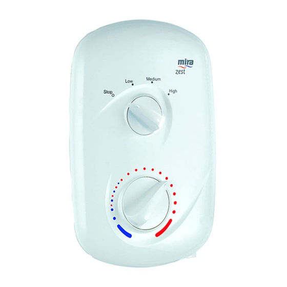
COMMISSIONING If you are unsure how electric showers work, please read through the Operation section before continuing. Make sure that the TOP control knob is in the 'STOP' position and that the electrical supply has been isolated. Turn the BOTTOM control knob fully anticlockwise to the full cold position. Turn the water supply fully on at the isolating valve, check that water is not leaking from the bottom of the case. -
Page 17: Operation
OPERATION Advice to Users Note! Read the Important Safety Information section first. Warning! The spray plate holes must be kept clear. The spray plate should be regularly removed and cleaned in descalent. Lack of regular spray plate cleaning will lead to poor performance and cause early failure of the appliance. - Page 18 Operation Instructions To turn the shower on Switch on the electrical supply at the double pole switch. Turn the power knob to High. Wait 15-20 seconds for warm water to reach the handset. For electrical economy, set the power knob to Medium. This setting will provide sufficient power when the supply water temperature is warmer, such as in the summer.
-
Page 19: Fault Diagnosis
FAULT DIAGNOSIS The troubleshooting information tabled below gives you details on probable causes and remedies should difficulties be encountered whilst the shower is in operation. Warning! There are no user serviceable components beneath the cover of the appliance. ONLY A COMPETENT TRADESPERSON SHOULD REMOVE THE FRONT COVER! Remedy Malfunction Cause... - Page 20 Malfunction Cause Remedy The power is off at the Switch on the power at the double pole switch. double pole switch. The fuse is blown or the Renew the fuse or reset the MCB/RCD has been MCB/RCD. If the fault persists, tripped, indicating contact the shower installer.
- Page 21 Malfunction Cause Remedy The temperature is set too Shower temperature Turn the temperature knob high. This is causing the cycles between hot anticlockwise to reduce the thermal switch to turn off and cold. water temperature. the heating element to DO NOT TAMPER with the reduce water thermal switch.
- Page 22 Malfunction Cause Remedy Resolve the blocked outlet, Water leaks from The pressure relief valve in and replace the tank assembly. the bottom of the tank been case near the outlet, triggered, (the shower has and there is no flow a pressure relief valve from the handset.
-
Page 23: Maintenance
MAINTENANCE Any maintenance must be carried out by a qualified tradesperson, following the instructions provided. Before replacing any parts, ensure that the underlying cause of the malfunction has been resolved. Warning! There are no user-serviceable components beneath the cover of the appliance. -
Page 24: Relief Valve Assembly - Resetting
Relief Valve Assembly - Resetting WARNING! Isolate the electrical and water supplies before removing the cover. Mains electricity connections are exposed when the cover is removed. Remove the three screws that hold the Screws cover, remove the cover. Note! The rubber ball is ejected to reduce the damage if the outlet is blocked or the appliance is frozen. -
Page 25: Spare Parts
SPARE PARTS Spare Parts List 406.27 Filter 439.75 Inlet Connector Assembly 439.76 Clamp Bracket Pack (components identified ‘A’) 439.77 Flow Reg Assembly 7.5/8.5 kW 439.79 Switch Assembly, Rotary 439.81 Cover Assembly, Zest 439.87 Terminal Block Assembly 439.88 Seal Pack (components identified ‘B’) 439.89 Screw Pack (components identified ‘C’) 439.90... -
Page 26: Spare Parts Diagram
Spare Parts Diagram 439.79 439.75 406.27 439.77 439.90 439.87 439.95 439.99 439.91 439.92 439.81... -
Page 27: Notes
NOTES... - Page 28 NOTES...
-
Page 29: Customer Service
CUSTOMER SERVICE 1057732-W2-A © Kohler Mira Limited, January 2006...
Need help?
Do you have a question about the Mira Zest and is the answer not in the manual?
Questions and answers