Table of Contents
Advertisement
Quick Links
Advertisement
Table of Contents

Related Manuals for Leetro MPC2810


Summary of Contents for Leetro MPC2810
- Page 1 MPC2810 Hardware Manual Rev. 1.0 December, 2008...
- Page 2 Both Step-Servo™ and Leetro™ are trademark of Leetro Automation Co., Ltd. Leetro’ s general policy does not recommend the use of its products in life support or aircraft applications wherein a failure or malfunction of the product may directly threaten life or injury. Per Leetro’ s terms and conditions of sales, the user of Leetro Automation Co., Ltd.
- Page 3 Thank you for buying and using ’ s Leetro™ motion controllers. MPC2810 is a high-performance universal motion controller developed by Leetro Automation Co., Ltd. Please read through this manual for specifications and proper use, especially the “ Safety Precautions”section. Your motion controller has been designed to work with both servo and stepper motors.
- Page 4 MPC2810 Motion Controller Hardware Manual Safety Warnings Please pay attention to following warnings to avoid any injury or machine damage. In this document, the following symbols are used to indicate the level of damages. Ignoring the warnings might cause injuries.
- Page 5 MPC2810 Motion Controller Hardware Manual card should be connected to the Breakout board first, then the motors and drives to the Breakout board. To disconnect the system correctly and securely, make sure to turn off the external power supply first.
- Page 6 MPC2810 Motion Controller Hardware Manual Warranty Information This is to certify that MPC2810 controllers are guaranteed by Leetro Automation Co., Ltd. to be free of all defects in material and workmanship for a period of 12 months from the date of delivery. The warranty does not apply to any defect caused by negligence, misuse (including environmental factors), accident, alteration, or improper maintenance.
- Page 7 Customers are responsible for the shipping costs. Product Application Precaution The Product is designed for general industrial applications. Leetro does not recommend the use of its products in life support or aircraft applications wherein a failure or malfunction of the product may directly threaten life or injury.
-
Page 8: Table Of Contents
3.2.2 Universal I/O Extension Cable-C4037..........24 3.2.3 Breakout board-P62-02 ..............26 3.3 C .....................29 ONNECTION 3.3.1 Connect MPC2810 to P62-01 ............29 3.3.2 Connect P2810 to Power Supply............30 3.3.3 Connect P62-01 to Motor Drive............30 3.3.3.1 OUTPUTS...................30 3.3.3.2 CONNECT ENCODER INPUTS ..........32 3.3.3.3 CONNECT DEDICATED INPUTS..........33 3.3.3.4 CONNECTING UNIVERSAL I/O ..........33... -
Page 9: Overview
1.1 Introduction Leetro™ MPC2810 is a high-performance 1 to 4-axis PCI-BUS card for stepper motors and digital servo motors. Multiple MPC2810 control cards can be put in a PC to control up to 16 axes. MPC2810 motion control card adopts IBM-PC and its compatible PC as the host computer. -
Page 10: The Manual Is For
MPC2810 Motion Controller Hardware Manual MPC2810 motion controller is widely used in the following areas: the laser processing machines, the CNC machines, the machining center, the robots, the X-Y-Z control set, the painting instruments, the engraving machines, the printing machines, the feeding machines, the marking machines, the coiling machines, the medical machines, the packing machines, the textile machines, the woodworking machines and the assemble line. - Page 11 Comparative position control output Interface commands are used for setting the universal outputs 1-4 as comparative position control outputs. Encoder latch MPC2810 motion controller can latch encoder feedback signals of 1-Ch and 2-Ch. Destination Position Verify Automatic destination error compensation ...
-
Page 12: Specifications
MPC2810 Motion Controller Hardware Manual 1.4 Specifications Form 1-1 MPC2810 Motion Control Card Specs Item MPC2810 Main interface PCI (3.3 or 5V) Axes 1 to 4 Encoder inputs (CH) 2-CH 2-CH, 32bit, 2147483647, A/B/Z phase (2Mpps), differential Encoder counter interface... -
Page 13: Typical Control System
Motor Breakout Board Worktable Fig.1-1 Control System using MPC2810 A typical motion control system that uses MPC2810 as motion control card is comprised of: MPC2810 motion control card and breakout board; PC or industrial control computer with PCI slot, Windows2000/XP operation system;... -
Page 14: Quick Installation
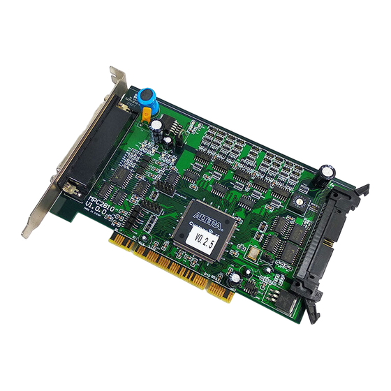
MPC2810 Motion Controller Hardware Manual 2 Quick Installation 2.1 Check Your Package Standard package list: 1* MPC2810 motion control card; 1* P62-01 breakout board or 1* P62-02 breakout board; 1* 62-pin shielded cable, 2m; 1* Software toolkit. - Page 15 MPC2810 Motion Controller Hardware Manual 16-CH universal Power converter 20-CH dedicated input circuit Dialer module 24V-5V Input circuit Indicator lights FPGA 8-CH universal 2 axes encoder 16-CH universal Pul/dir output circuit input circuit inputs circuit output Fig. 2-1 MPC2810 Layout Diagram...
- Page 16 MPC2810 Motion Controller Hardware Manual (2)Breakout board-P62-01 for MPC2810 110mm D41 D39 D37 D35 D33 D31 D29 D27 D25 D23 D21 D42 D40 D38 D36 D34 D32 D30 D28 D26 D24 D22 85mm Fig. 2-3 P62-01 Breakout Board P62-01 Dimensions: (mm) Fig.
- Page 17 MPC2810 Motion Controller Hardware Manual (3)Breakout board-P37-05 for I/O extension board (mm) 68.5 Fig. 2-5 P37-05 Breakout Board Mounting Hole Dimensions: 3.5mm. (4)Breakout board-P62-02 for MPC2810 CN2 CN1 ENC1 ENC2 AXIS2 AXIS1 AXIS4 AXIS3 Fig. 2-6 P62-02 Breakout Board...
-
Page 18: Hardware Installation
2.4 Software Installation The motion control card can be operated under either Win2000 or WinXP operating systems. Windows can automatically detect the MPC2810 when plugged into the PC, and its Plug-and-Play capability will automatically install the card. When you see the pop-up dialog box indicating that new device is found, please click “... - Page 19 MPC2810 Motion Controller Hardware Manual Run setup program under root directory of installation CD. Then click “ Next”to continue the installation. Fig. 2-7 Welcome window Select components to be installed. Fig. 2-8 Select components window...
- Page 20 MPC2810 Motion Controller Hardware Manual Select the destination location of installation files. Default path: C:\Program Files\MPC2810. Click Browse to choose a preferred path. Fig. 2-9 Choose destination location window Click Next to start the installation.
- Page 21 MPC2810 Motion Controller Hardware Manual Fig. 2-10 Copying files Finish the installation. Click Finish to complete the installation. Fig. 2-11 Installation completed When the installation completed, system will indicate to restart the...
- Page 22 MPC2810 Motion Controller Hardware Manual computer. Click OK to have the system restarted immediately. If you want to restart the system later, click Cancel. MPC2810 can only be used after the system restarted. Fig. 2-12 Restart indication dialog box To check if the installation completed successfully, open the MPC2810 folder located in destination path.
- Page 23 MPC2810 Motion Controller Hardware Manual Fig. 2-14 VBDemo1 window With VBDemo1 example program user can primarily test the control system and easily learn how to develop MPC2810. Click About to learn more about MPC2810 hardware and software version information. Run “ VBDemo2” , the following motion control performance window will be shown as follows: Fig.
- Page 24 MPC2810 Motion Controller Hardware Manual Motion track and speed curve are shown in the left frame. Parameters settings on the linear/circular interpolation, the jogging motion and the encoder are shown in the right frame. The frame OTHERS is used for testing universal I/Os and special inputs.
- Page 25 MPC2810 Motion Controller Hardware Manual “ VCDemo3”provides no source code. It can read *.DXF file, test I/O & commands. (Refer to Chapter4) “ CmdMove1” demonstrates batch processing and short line segments tracking examples. Fig. 2-17 CmdMove1 window ...
- Page 26 MPC2810 Motion Controller Hardware Manual Fig. 2-18 HandwheelorGearHandle window “ InterruptHandle”demonstrates event handling example. Fig. 2-19 InterruptHandle window...
- Page 27 Sub-directory “ VB” : Module file MPC2810.bas used for developing VB execution program Sub-directory “ VC” : file used for dynamically loading dynamic link library(“ LoadMPC2810.cpp” and “ LoadMPC2810.h” ) and file used for static and dynamic link library (“ MPC2810.h”and...
-
Page 28: Uninstall Software
2. Uninstall the former program 3. Run the later setup program 4. If it is developed by Visual Basic6.0, please update “ MPC2810.dll” and “ MPC2810.bas”in the Microsoft Visual Basic Project. 5. If it is developed by Visual C++6.0, please update “ MPC2810.dll” , “... -
Page 29: How To Use
If four cards are used, 0x0H should be the ID of the first card, 0x1H to the second card, 0x2H to the third card, and 0x3H to the fourth card. When it is applied in multi-MPC2810, the coupling relationship between card and axis numbers are: Card 1: Axis 1 –4... -
Page 30: Signal Interface
MPC2810 Motion Controller Hardware Manual 3.2 Signal Interface 3.2.1 Breakout board-P62-01 D41 D39 D37 D35 D33 D31 D29 D27 D25 D23 D21 D42 D40 D38 D36 D34 D32 D30 D28 D26 D24 D22 Fig. 3-2 P62-01 Breakout board Layout Diagram... - Page 31 MPC2810 Motion Controller Hardware Manual EL2+ Axis-2 Forward Limit Signal ORG2 Axis-2 Homing Signal Axis-3 Ramp-down Signal EL3- Axis-3 Reverse Limit Signal EL3+ Axis-3 Forward Limit Signal ORG3 Axis-3 Homing Signal Axis-4 Ramp-down Signal EL4- Axis-4 Reverse Limit Signal EL4+...
-
Page 32: Universal I/O Extension Cable-C4037
3.2.2 Universal I/O Extension Cable-C4037 16 universal inputs and 16 universal outputs can be extended with the installation of C4037. Connect MPC2810 to external 37-pin cable through the C4037. For the convenience of wiring, the I/O extension Breakout board P37-05 can be used. - Page 33 MPC2810 Motion Controller Hardware Manual IN10 Universal input-10 IN11 Universal input-11 IN12 Universal input-12 IN13 Universal input-13 IN14 Universal input-14 IN15 Universal input-15 IN16 Universal input-16 OUT9 Universal output-9 OUT10 Universal output-10 OUT11 Universal output-11 OUT12 Universal output-12 OUT13 Universal output-13...
-
Page 34: Breakout Board-P62-02
AXIS3 Fig.3-3 P62-02 Breakout board Layout Diagram Table 3-4 P62-02 Interface Description Connectors Description Connected to MPC2810’ s DB62 interface Connected to C4037’ s DB37 interface 24-pin for universal outputs 18-pin for universal inputs and alarm input 24V power supply... - Page 35 MPC2810 Motion Controller Hardware Manual Universal output-23 Universal output-22 Universal output-21 Universal output-20 Universal output-19 Universal output-18 Universal output-17 Universal output-16 Universal output-15 Universal output-14 Universal output-13 Universal output-12 Universal output-11 Universal output-10 Universal output-9 Universal output-8 Universal output-7 Universal output-6...
- Page 36 MPC2810 Motion Controller Hardware Manual Universal input-9 Universal input-8 Universal input-7 Universal input-6 Universal input-5 Universal input-4 Universal input-3 Universal input-2 Universal input-1 Alarm input Table 3-7 Connector CN5 Description Pin # Description Compulsory 24V GND, input ( Compulsory DC24V...
-
Page 37: Connection
Power off the PC Plug MPC2810 into the PCI-slot of the PC Connect JP1 interface of MPC2810 to J1 interface of P62-01 with the 62-pin shielded cable as shown in figure 3-3: MPC2810 Shielded cable P62-01 Fig. 3-4 Connect Motion Control Card to Breakout Board... -
Page 38: Connect P2810 To Power Supply
Fig. 3-5 Connect Breakout Board to Power Supply 3.3.3 Connect P62-01 to Motor Drive 3.3.3.1 Outputs Two pulse output modes for MPC2810: Pul/Dir, and CW/CCW. Default mode is Pul/Dir. User can change the output mode of each axis using “ set_outmode” command. (Refer to Programming Manual). - Page 39 MPC2810 Motion Controller Hardware Manual Pul/Dir Mode Motor Drive P62-01 Motor Drive P62-01 Dir Signal Dir Signal DIR+ DIR- Pul Signal Pul Signal PULSE PULSE+ PULSE- (a) Differential Pul/Dir Mode (b) Single-ended Pul/Dir Mode Fig. 3-7 Pul/Dir Output (2)CW/CCW Mode...
-
Page 40: Connect Encoder Inputs
MPC2810 Motion Controller Hardware Manual 3.3.3.2 Connect Encoder Inputs 2- CH encoder interfaces receiving A-phase, B-phase and Z-phase signals are available. D28, D29 (axis-1) and D34, D35 (axis-2) function as the differential ports for encoder latching inputs once the encoder latching functionality activated. -
Page 41: Connect Dedicated Inputs
Dedicated switch inputs include: limit, Ramp-down, homing and external alarm signals. The switch could be contact-switch or NPN-output sensor proximity switch. The connection diagram is as follows. No dedicated switch outputs for MPC2810. User can set universal output1~4 as comparative position output ports using the command enable_io_pos - DC24/12... - Page 42 Fig.3-14 Universal Input Connection (2) Universal Output Loop Open-collector output of MPC2810 can be connected to relay, and photo coupler. The max output current is 200mA, voltage is 24V. It can be used as switch inputs of servo system (Servo-ON, Error Counter Reset) or be used for driving intermediate relay or photo coupler of 24DCV.
- Page 43 MPC2810 Motion Controller Hardware Manual MPC2810 Relay Output DC24 ULN2803 - (b) Drive Relay Fig. 3-16 GO Connection Diagram...
-
Page 44: System Debugging
Debugging software is to test if the system can work normally, confirm if the connection is all right, and track some simple motions. 4.1 Destination path When software installation completed, folder MPC2810 will be automatically created (Default installation path: \ Program Files). The directory tree is as follows: Fig.4-1 MPC2810 Directory Tree... -
Page 45: How To Use The Debugging Program
MPC2810 Motion Controller Hardware Manual Files\MPC2810\Demo\VCDemo\VCDemo3. It is used for testing commands and I/Os of MPC2810. Modules are built in VCDemo3 to process DXF file, 2D trajectory motion can be generated with this program. Display resolution: 1024* 768 (Recommend). 4.2 How to use the debugging program After running VcDemo3.exe, five modules will present as fig. - Page 46 MPC2810 Motion Controller Hardware Manual Look-ahead and Batch-processing modes are improved in the motion mode setting. Look-ahead benefits being higher machining speed and less machining impact. The controller will set the optimized parameters when user sets the max acceleration, velocity and others. It makes much better performance in the micro-segment trajectory motion.
- Page 47 MPC2810 Motion Controller Hardware Manual Fig. 4-4 Test PtoP Motion (3). Test IO Module Clicking the button is to enter IO Test Module. Standard Inputs and Specific Inputs status will be shown as Fig. 4-5. Red presents active-high. Green presents active-low. Blue presents error..
- Page 48 (4). Test Command Module Clicking the button is to enter the Test Command module. In this module, users can test all functions of MPC2810. After double-clicking the parameter column to enter the data, clicking the button to carry out the command.
- Page 49 MPC2810 Motion Controller Hardware Manual Fig. 4-6 Test Command (5). System Setting Module As Fig. 4-7 shown, Pulse Out Mode, Feedback and Home Mode will be set in this window. Fig. 4-7 System Setting...
-
Page 50: Typical Connection
MPC2810 Motion Controller Hardware Manual 5 Typical Connection 5.1 Connect MPC2810 to DMD808 Stepper Motor Drive Stepper motor drive Motion control card Axis-1 Direction- Dir- Dir+ Axis-1 Direction+ Pul- Axis-1 Pulse- Pul+ Axis-1 Pulse+ DCV24+ DC24/12 GND24... -
Page 51: Connect Mpc2810 To Panasonic Minas A Series Servo Motor Drive
MPC2810 Motion Controller Hardware Manual 5.2 Connect MPC2810 to Panasonic MINAS A Series Servo Motor Drive Motion control card Servo motor driver Encoder A1- Encoder A1+ Encoder B1- Encoder B1+ Encoder Z1- Encoder Z1+ SIGN2 Axis-1 Direction - SIGN1 Axis-1 Direction +...
Need help?
Do you have a question about the MPC2810 and is the answer not in the manual?
Questions and answers