
Related Manuals for Leetro MPC6575


Summary of Contents for Leetro MPC6575
- Page 1 MANUFACTURER’S MANUAL MPC6575 Beta 1.0 Leetro Automation Co., Ltd. Building 8-B Dayi Zone of Incubating Hi-Tech No.1 South 2nd Keyuan Rd Chengdu 610041 CHINA www.leetro.com...
- Page 2 Step-Servo and Leetro™are trademark of Step-Servo Co., Ltd. Step-Servo Co., Ltd.’s general policy does not recommend the use of its products in life support or aircraft applications wherein a failure or malfunction of the product may directly threaten life or injury.
-
Page 5: Table Of Contents
MPC6575-Close-loop Laser Engraving &Cutting Controller (Rev. 1.0) Table of Content CHAPTER 1 PREFACE ................1 CHAPTER 2 OVERVIEW ................2 MPC6575 I ....................2 NTRODUCTION ..................2 ONTROL YSTEM ONFIGURATION CHAPTER 3 INSTALLATION..............3 ........................3 OARD PAD03 ..........................1 CHAPTER 4 HARDWARE INTERFACES..........1 MPC6575/CPU I ....................1... - Page 6 MPC6575-Close-loop Laser Engraving &Cutting Controller (Rev. 1.0) 6.3.6 Work Interface ..........................22 6.3.7 Status Interface..........................23 CHAPTER 7 POP TEXT DISPLAY ............24 & D ROGRAM OWNLOAD ......................24 7.1.1 Wiring ............................24 7.1.2 Download Text Display Program ....................24 7.1.3 Panel of Text Display........................25 7.1.4...
-
Page 7: Chapter 1 Preface
Preface Chapter 1 Preface Thank you for using Leetro™ motion controllers. MPC6575, specially designed for close-loop laser engraving and cutting system. This manual will instruct you on using MPC6575 in details. Please read the instructions carefully before using MPC6575. User should debug the system with full consideration on... -
Page 8: Chapter 2 Overview
User can edit graphics, set parameters, and optimize path to develop a process file using computer. Copy the process file to USB stick, and load it to MPC6575 through the USB interface in the controller. Then Run the processing work with PAD03 control panel. -
Page 9: Chapter 3 Installation
Installation Chapter 3 Installation 3.1 Main Board The mainboard adopts six M3 bolts... - Page 11 Installation 3.2 PAD03...
-
Page 13: Main Board Pad03
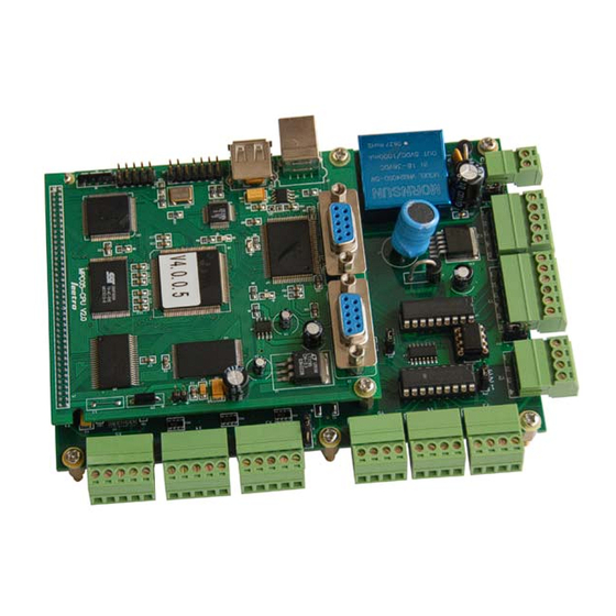
Hardware Interfaces Chapter 4 Hardware Interfaces MPC6575 controller is composed of two parts: 1)MPC6575/MC motion control daughter board 2)MPC6575/CPU CPU mainboard User can find corresponding mark on each board 4.1 MPC6575/CPU Interface (For Human-Machine Interface debug only.) Support HMI based on Modbus... - Page 14 MPC6575-Close-loop Laser Engraving &Cutting Controller (Rev. 1.0) Wiring of J2 and EasyView RS232 (PLC): (PLC) EasyView MPC6575/J2 Wiring of J2 and PAD03 RS232: PAD03 MPC6575/J2 Wiring of J2 and BYDseries HMI RS232 (PLC): BYDseries HMI (PLC) MPC6575/J2...
-
Page 15: Mpc6575/Mc Interfaces
Hardware Interfaces 4.2 MPC6575/MC Interfaces Please pay attention to the version of MPC6575/MC. MPC6575MCV1.1 Caution 4.2.1 Pin Array Group 1: POWER (Input Power Pins) 24VDC+ 24V Ground Group 2: IN (Inputs Pins) INT2 INT3 INT4 5/24V Foot Uncapping Speed-zero General input 4... - Page 16 MPC6575-Close-loop Laser Engraving &Cutting Controller (Rev. 1.0) OUT1 OUT2 OUT3 OUT4 OUT5 OUT6 Blow-off Process USB stick General General Speed-zero clamp On/Off completion indicator output 3 output 4 output indicator light light Group 4: LASER (Laser Control Signal Pins) PWM+...
- Page 17 Hardware Interfaces POWER: Input Power Pin (24VDC) Remark: MPC6575 adopts single 24VDC power. The other power pins are used for output power of the controller. MPC6575 adopts single 24VDC. User must use proper and reliable power supply. Exorbitant voltage could result in...
-
Page 18: Chapter 5 Pad03 Operation
MPC6575-Close-loop Laser Engraving &Cutting Controller (Rev. 1.0) Chapter 5 PAD03 Operation 5.1 PAD03 Panel Datum: Laser head will move to the origin of the machine slowly. Laser: Laser on/off. Stop: Cease the processing operation. Test: The laser head will run along the outline border of the processing data. -
Page 19: Connection
PAD03 Operation 5.2 Connection Connect MPC6575/J2 to PAD03 RS232 PAD03 MPC6575/J2 2 TXD 3 RXD 5 GND 9 +5V... -
Page 20: Startup Message
When the power is on, following message will be displayed (V3.0.10 is the version number of PAD03): SYSTEM STARTING, PLEASE WAIT… V 3.0.10 5.4 Main Interface If there’s no communication problem with MPC6575, main interface will be shown as follows: FILE 100 % SPEED 100 / 100 % POWER 0 : 0 : 15 TIME File: The saved file name loaded to MPC6575 controller. -
Page 21: Supporting Interface
PAD03 Operation Press Laser to beam according to the settings of LASER SET. Press Datum to have the X-axis and Y-axis make homing motion simultaneously; DATUM… X and Y axes will not stop until they reach the origin point or the user press Stop button. Press Test to generate the contouring motion, and following text displays. - Page 22 MPC6575-Close-loop Laser Engraving &Cutting Controller (Rev. 1.0) PMOV LANGUAGE CUT BDR: Laser head will move a rectangle with laser on according to the size of the graphics. LAS SET: Select this option and press . The LAS SET interface is as follows.
-
Page 23: Processing Interface
PAD03 Operation 5.6 Processing Interface Press Start to enter the processing interface shown as follows.. FILE 100 % SPEED 100 / 100 % POWER 0 : 0 : 15 TIME File: Name of the file which is to be processed. Speed: Percentage of the processing speed. -
Page 24: Download From Usb Stick
MPC6575-Close-loop Laser Engraving &Cutting Controller (Rev. 1.0) Once the processing finished, only Start/Pause, and Esc buttons can be effective. To enter the processing interface, press Start/Pause. To return to the main interface, press Esc. 5.7 Download from USB Stick Return to the main interface, plug the USB stick into the controller and the user interface of... -
Page 25: Stop Caused By Hardware Limit
PAD03 Operation Software detects that the processing file goes beyond the worktable range. Solution: Adjust the position of the laser head till the whole processing file is within the worktable range. 5.8.3 Stop Caused by Hardware Limit HARD LIMIT. PROCESSING STOP In the status that no Datum command is given and the machine is set as immediate processing mode, the above message will be shown for stop error caused by processing file going beyond the worktable range. -
Page 26: Mismatched Dll And Firmware
MPC6575-Close-loop Laser Engraving &Cutting Controller (Rev. 1.0) version are mismatched, contact your supplier for correct one. Run laserCut program, and re-download the configuration file. 5.8.6 Mismatched DLL and Firmware MiSMATCHED Causes: The DLL with which the processing file was created is unmatched with the firmware version. -
Page 27: Speed-Zero Clamp
PAD03 Operation Value of over-voltage limit is set to be too small. Servo motor drive is limited. 5.8.9 Speed-Zero Clamp Speed-Zero Clamp System is under speed-zero clamp: Speed-zero clamp input is effective. USB flash disk should be formatted to FAT16, if fail to follow this instruction, the flash disk cannot be detected by the controller. -
Page 28: Chapter 6 Touch Screen
Programming Cable: Connect the touch screen to the serial interface of the PC. With this cable, user can download the edited interface program file from the PC to the touch screen. Communication Cable: Connect the touch screen to the serial interface of MPC6575. How to Make WeinView/EasyView Programming Cable... - Page 29 Touch Screen Select the serial port (i.e. COM1) and enter the EasyBuilder edit window. The serial number of ports related with the practical wiring. Click Open and following window pops up. Select and open the edited interface program file in *.epj format:...
-
Page 30: Connect To Two Touch Screens
MPC6575-Close-loop Laser Engraving &Cutting Controller (Rev. 1.0) Select Compile in the toolbar to compile the program file. Then click Download to download the compiled file to the touch screen. 6.2 Connect to Two Touch Screens 6.2.1 MT510 Wiring MT510 PC[RS-232] 9 针D型公座... -
Page 31: Operation
PLC[RS-232]9-pin Male PLC[RS-232]9-pin Female Header Header 8 RD 2 TD 7 TD 3 RD 5 GND 5 GND Connect MPC6575 to Host Touch Screen: MPC6575 Host Touch Screen [RS-232]9-pin Female [RS-232]9-pin Female Header Header 2 TD 3 RD 3 RD... -
Page 32: Laser Interface
MPC6575-Close-loop Laser Engraving &Cutting Controller (Rev. 1.0) Three language options can be found in the menu interface such as Simplified Chinese (GB), Traditional Chinese (BIG5), and English. The other three options are Laser Set, Jog Set and Main Interface. 6.3.3 Laser Interface Press the Laser button in the menu interface to enter the Laser interface. -
Page 33: Jog Interface
Touch Screen Press OK to enter the main interface. 6.3.4 Jog Interface Press the Jog Set button in the menu interface to enter the Jog Set interface. Jog distance can be set in Jog Set interface. If the jog distance is default 0.0mm (precision: 0.1mm), user can hold down the direction buttons to move the laser, and loose the direction button to stop the laser. -
Page 34: Work Interface
MPC6575-Close-loop Laser Engraving &Cutting Controller (Rev. 1.0) Parameter Descriptions: File: Current file name. File name should not be longer than 8 letters or numbers. Sum: Total number of the files saved in the MPC6575. No.: Serial number of current file : Shift to the previous file. -
Page 35: Status Interface
Esc: Press Esc to return to the main interface. 6.3.7 Status Interface Once download signal of USB stick or datum signal is detected by MPC6575, Following message would pop up automatically.the user interface would shift to the USB stick download interface automatically. -
Page 36: Chapter 7 Pop Text Display
Programming Cable: Connect the text display to the serial interface of the PC. With this cable, user can download the edited interface program file from the PC to the text display. Communication Cable: Connect the text display to the serial interface of MPC6575. How to Make Text Display Programming Cable... -
Page 37: Panel Of Text Display
Speed: The percentage of the processing speed. This value can be adjusted within the range of 0-100%. The default value is 100%. Sum: Total number of the files saved in the MPC6575. Power: The percentage of the laser power. The first value indicates the laser power percentage at low speed. -
Page 38: Jog Set Interface
MPC6575-Close-loop Laser Engraving &Cutting Controller (Rev. 1.0) : Press this button to activate the cursor. : The four buttons are used for controlling the movment of the laser. They correspond to Upwards, Downwards, Leftwards and Rightwards respectively. : Press this button to shift to the jog set interface. -
Page 39: Laser Set Interface
POP Text Display Press to return to the main interface. The other buttons are invalid. Precision of this parameter is 0.1mm. The set parameter can be saved automatically if power’s off. 7.1.6 Laser Set Interface When cursor is nonactivated, press to shift the interface from main interface to the Laser Set interface. -
Page 40: Usb Stick Download Interface
7.1.8 USB Stick Download Interface Once USB stick is detected plug in MPC6575, the user interface would shift to the USB stick download interface automatically. In this interface the download status will be shown in the display. When 100% work is downloaded to the controller, the text display shows the message Remove USB Stick. -
Page 41: Chapter 8 Develop Hmi
Develop HMI Chapter 8 Develop HMI All HMIs support Modbus Protocol can be developed to the control panel of MPC6575.Take MT506LV45WV as an example: 8.1 Protocol and System Setting Standard Modbus Protocol PLC Type: Modbus RTU Baud rate: 9600bps Data bit: 8-bit;... - Page 42 MPC6575-Close-loop Laser Engraving &Cutting Controller (Rev. 1.0) Components Functionality Type Rmark Address Device Attributes Type Start/Pause Button ON/OFF shift Pause Button Datum Button Stop Button ON/OFF revert Button ON/OFF revert Down Button ON/OFF revert Left Button ON/OFF revert Right Button...
- Page 43 Develop HMI Addresses and functionalities of PLC register are as shown in following table: Device Data Data length Address Functionality Type Type byte Percentage o f processing speed (%) Laser power corresponding to high speed Laser power corresponding to low speed Set the pieces to be processed Reserve Completed pieces...
-
Page 44: Demo
MPC6575-Close-loop Laser Engraving &Cutting Controller (Rev. 1.0) 1: In pausing Speed-zero 0: Paused jogging clamp Cancel stops speed-zero clamp Start 1: plug in 1: Bordering 1: Start download Z-axis Datum Border 0: Finished 0: Stop Pause stick datum 0: Stop... -
Page 45: Chapter 9 Download Data
Then remove the USB stick, and DSP firmware program will be started. (7) If MPC6575 fails to work after the USB stick being removed, probably something is wrong during the upgrade process. Please repeat the above upgrade steps. (8) If MPC6575 can’t work yet after repeating the above steps, contact your supplier. -
Page 46: Download Data
(2) Electrify the MPC6575 (3) Plug the USB stick into the MPC6575. (4) If the indicator light D1 in the MPC6575/CPU keeps shining for seconds or minutes (depend on the file size), the controller is downloading processing file. (5) If D1 flashes swiftly, download finished;... -
Page 47: Chapter 10 Work Status Indicator Lights
10.1.1 Work Status Indicator Light Working status of MPC6575 is indicated through the 8 LED indicator lights in MC card and 4 indicator lights in CPU card. Please refer to Chapter 4 to learn the position of the indicator lights. - Page 48 MPC6575-Close-loop Laser Engraving &Cutting Controller (Rev. 1.0) ON/OFF status indicated by following symbols: Indicates the light is shining Indicates the light is off Error codes descriptions are as follows: Error Code Lights Status(Left to right: D8 to D1) Causes Solution...
- Page 49 Please restart MPC6575 if any error occurred to resume to the normal status. Then solve the problem according to the above error codes descriptions. Caution...
- Page 50 MPC6575-Close-loop Laser Engraving &Cutting Controller (Rev. 1.0)
-
Page 51: Chapter 11 Faq
11.1 USB Stick Indicator Light 11.1.1 Functionality MPC6575 is installed inside a machine, so that the user can’t see the indicator lights in the controller. With a USB stick, the user can download the processing data to MPC6575 easily and observe the download status easily with an LED by leading out the indicator light of USB stick to the control panel of the machine. -
Page 52: External Process Completion Indicator Light
LED or other indicator light showing the processing status. 11.3.2 Instruction Pin OUT2 (Process completion indicator light signal) in MPC6575/MCV1.1 board can be used for driving relay or LED to indicate if the process is completed. 11.4 Blow-off 11.4.1 Functionality... -
Page 53: Instruction
11.4.2 Instruction Pin OUT1(Blow off ON/OFF signal) in MPC6575/MC board is controlled by the machining commands during the processing. The blow-off device will be on when the port is low-voltage. When the port is high-voltage, blow-off device will be off.
Need help?
Do you have a question about the MPC6575 and is the answer not in the manual?
Questions and answers