Advertisement
Table of Contents
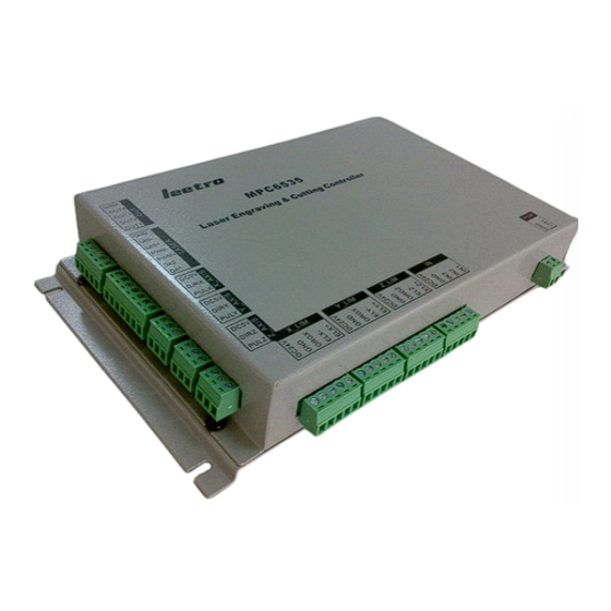
MPC6535 User Manual
V 1.3
MPC6535 improves major performance compared to MPC6515 in
(a). better motion control around the corner; and
(b). less interfering thanks to the aluminum case.
Leetro Automation Co., Ltd
Building 8-B, Dayi Zone of Incubating Hi-tech,
N o.1 South 2nd Keyuan Road,
Chengdu 610041, CHINA
www.leetro.com
- 1 -
Advertisement
Table of Contents

Related Manuals for Leetro MPC6535


Summary of Contents for Leetro MPC6535
- Page 1 MPC6535 User Manual V 1.3 MPC6535 improves major performance compared to MPC6515 in (a). better motion control around the corner; and (b). less interfering thanks to the aluminum case. Leetro Automation Co., Ltd Building 8-B, Dayi Zone of Incubating Hi-tech, N o.1 South 2nd Keyuan Road,...
- Page 2 2.1 Run the setup.exe and follow the “ next step”instruction to install LaserCut program into your computer. 2.2 Install MPC6535 controller board: mounting the board in the machine firmly. Must make the machine house wires with GROUND! 3. Wiring Diagram 3.1 Size (mm)
- Page 3 3.2 Pins Pin Definition Group +24V 24V GND Cover Pedal Water Opening +24V Switch Protect Protect Z-axis Z-axis Z_LIM Z-axis -Limit +24V +Limit Home Y-axis Y-axis Y-axis +24V Y_LIM +Limit -Limit Home X-axis X-axis X-axis X_LIM +24V +Limit -Limit Home Z-axis Z-axis Z_AXIS...
- Page 4 3.3 Control System 3.4 Interface Circuit 3.4.1 Pulse+Dir Output-port - 4 -...
- Page 5 3.4.2 IO Input-port Circuit 3.4.3 IO Output-port Circuit - 5 -...
- Page 6 3.4.4 Laser Firing Circuit 3.4.5 Laser PWM - 6 -...
- Page 7 3.4.6 Laser Power DAC Interface 3.5 Wiring Instruction 1. Must be careful with the positive and the negative end of 24VDC 2. Connecting controller and drive 3. Connecting Datum Switch 4. Connecting Limit Switch 5. Connecting laser power supply 6. Connecting other control ports 4.
- Page 8 4.5 Start working. 5. Others 1. Must be careful with the positive and negative ends of MPC6535’ s power supply 2. Must turn the power off when disconnect the cable between control PAD and the board. 3. Make sure the metal case of MPC6535 wires to GROUND firmly 4.
Need help?
Do you have a question about the MPC6535 and is the answer not in the manual?
Questions and answers