Table of Contents
Advertisement
Quick Links
INSTRUCTIONS - PARTS LIST
684-000
Revision D
This manual contains IMPORTANT
WARNINGS and INSTRUCTIONS
READ AND RETAIN FOR REFERENCE
Stubby
®
10:1 PRESIDENT
PUMP
with Priming Piston
for Lubricating Products Only
1800 PSI (124 bar) MAXIMUM WORKING PRESSURE
180 PSI (12.4 bar) MAXIMUM AIR INLET PRESSURE
Model: 965-124
INDEX
Safety Warnings ............................... 2, 3, 4
Typical Installation ............................ 7
Installation ........................................ 7
Operation .......................................... 8
Maintenance ..................................... 8
Troubleshooting ................................ 9
Service ............................................. 10
Displacement Pump Repair .............. 11, 12
Check Valve Adjustment ................... 12
Parts List ........................................... 13
Parts Drawing ................................... 14
Accessories ...................................... 15
Dimensional Drawing ........................ 16
Technical Data .................................. Back Cover
Warranty ........................................... Back Cover
WARNING
PRIMING PISTON HAZARD
This pump has a priming piston which moves up and down inside the foot valve during operation. This piston
could pinch or amputate your fingers as it moves up and down. To reduce the risk of injury, keep your fingers
and all tools away from the slots in the foot valve during operation and whenever the air and fluid pressure in
the pump is not fully relieved.
WARNING
HAZARD OF USING FLUIDS CONTAINING HALOGENATED HYDROCARBONS
Never use 1, 1, 1-trichloroethane, methylene chloride, other halogenated hydrocarbon solvents or fluids
containing such solvents in this equipment. Such use could result in a serious chemical reaction, with the
possibility of explosion, which could cause death, serious bodily injury and/or substantial property damage.
Consult your fluid suppliers to ensure that the fluids being used are compatible with aluminum and zinc parts.
GRACO INC. - EAS, P.O. Box 1441, MINNEAPOLIS, MN 55440
©COPYRIGHT 1997 GRACO INC.
Advertisement
Table of Contents

Related Manuals for Graco PRESIDENT 965-124


Summary of Contents for Graco PRESIDENT 965-124
-
Page 1: Table Of Contents
Consult your fluid suppliers to ensure that the fluids being used are compatible with aluminum and zinc parts. GRACO INC. - EAS, P.O. Box 1441, MINNEAPOLIS, MN 55440 ©COPYRIGHT 1997 GRACO INC. - Page 2 WARNING FLUID UNDER HIGH PRESSURE CAN CAUSE SERIOUS INJURY. FOR PROFESSIONAL USE ONLY. OBSERVE ALL WARNINGS. Read and understand all instruction manuals before operating equipment. TERMS Be sure you red and understand each of these FLEXIBLE EXTENSION: A flexible rubber hose terms before reading the rest of the manual.
-
Page 3: Safety Warnings
Pressure Relief Procedure Medical Alert - Airless Spray Wounds To reduce the risk of serious bodily injury, including If any fluid appears to penetrate your skin, get injection, or splashing in the eyes or on the skin; EMERGENCY MEDICAL CARE AT ONCE. DO always follow this procedure whenever you shut off NOT TREAT AS A SIMPLE CUT. - Page 4 To ground the pump, loosen the grounding lug Grounding locknut (A) and washer (B). Insert one end of a 12 To reduce the risk of static sparking, ground the ga (1.5mm ) minimum ground wire (D) into the slot pump and all the spray equipment used or located in lug (C) and tighten locknut securely.
- Page 5 MOVING PARTS HAZARD The piston in the air motor, located behind the air motor plates, moves when air is supplied to the motor. Moving parts can pinch or amputate your fingers or other body parts. KEEP CLEAR of moving parts when starting or operating the sprayer.
- Page 6 DO NOT expose cause a fluid injection injury or other serious bodily Graco hose to temperatures above 180°F injury or property damage.
-
Page 7: Typical Installation
TYPICAL INSTALLATION Grounded Air Line Air Regulator Bleed-type Master Air Valve (required) Grounded Dispensing Hose Air Filter Dispensing Valve Air Line Oiler Ground Wire (required) INSTALLATION NOTE: Reference numbers and letters in WARNING parentheses in the test refer to the Typical The bleed-type master air valve (B) is required to Installation, Figure 1, 2 and the Parts Drawing. -
Page 8: Operation
OPERATION WARNING Open the bleed-type master air valve. Open the To reduce the risk of serious bodily injury, including dispensing valve and slowly open the air regulator until the pump is running smoothly. After all the air injection, always follow the Pressure Relief is purged, close the dispensing valve - the pump Procedure whenever you shut off the pump, and will start and stop as the valve is opened and... -
Page 9: Troubleshooting
TROUBLESHOOTING PROBLEM CAUSE SOLUTION Pump fails to operate, or no fluid Inadequate air supply pressure or Increase air supply; clear flow restricted air lines. Closed or clogged valves. Open; clean Clogged fluid lines, hoses, Clear * valves, etc. Damaged air motor Service air motor Exhausted fluid supply Refill and reprime or flush... -
Page 10: Service
SERVICE WARNING WARNING Moving parts can pinch or amputate your fingers or Pressure Relief Procedure other body parts. When the pump is operating, the To reduce the risk of serious bodily injury, including injection or splashing in the eyes or on the skin, priming piston (located at the pump intake) and the always follow this procedure whenever you shut off air motor piston (located behind the air motor... -
Page 11: Displacement Pump Repair
Displacement Pump Repair Before you start: NOTE: To replace the throat packings, follow the procedure given in your separate air motor 1. A packing repair kit, part no. 206-927, is manual, 306-982, supplied, before continuing available. This kit includes two glands and with this procedure. -
Page 12: Check Valve Adjustment
15. Insert foot valve packings (30) into poppet check (6) (replace if necessary). 11. Screw the piston assembly onto the connecting rod (3) and adjust the ball travel as instructed 16. Slide poppet check containing foot valve packings onto priming rod (8) with beveled in Check Valve Adjustment. -
Page 13: Parts List
2. Check the parts list to identify the correct part * Included in Repair Kit 206-927 number; do not use the ref. no. when Keep on hand to reduce “down time” ordering. Order all parts from your nearest Graco distributor. 6 digit PART NUMBER... -
Page 14: Parts Drawing
PARTS DRAWING Model: 965-124 Includes items 1-30 Ref. No. 18 Packing Detail PRESIDENT 6, 30 Ref. No. 18 Packing Detail at Upper Left... -
Page 15: Accessories
ACCESSORIES (Must be purchased separately) AIR LINE FILTER PUMP RUNAWAY VALVE 215-362 250 PSI (17.5 bar) MAXIMUM WORKING PRESSURE Shuts off air to pump automatically if it senses that the 106-149 1/2” npt inlet & outlet pump is running too fast, a condition caused by a depleted fluid supply. -
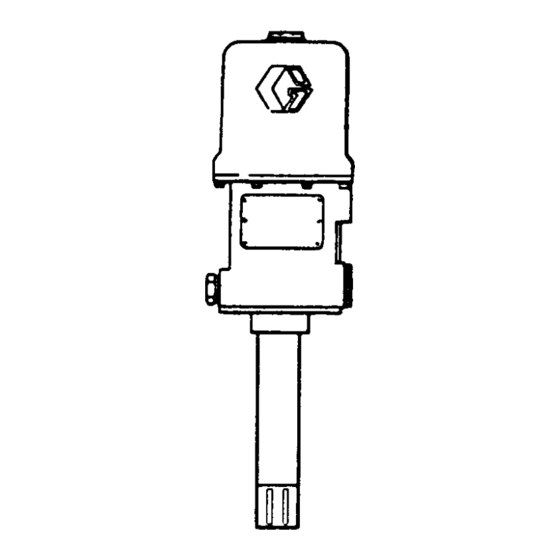
Page 16: Dimensional Drawing
DIMENSIONS 14 1/2” 1/2” npt (368.3 mm) 5” (127 mm) 29 1/4” (743 mm) 6 3/4” (171.4 mm) 14 15/16” (385 mm) 1 1/4” (31.8 mm) 1” 3” (25.4 mm) (76.2 mm) Bottom View Model: 965-124 Weight: 29 lb. (13 Kg) 5 1/2”... -
Page 17: Technical Data
Graco’s written recommendations. This warranty does not cover, and Graco shall not be liable for, any malfunction, damage or wear caused by faulty installation, misapplication, abrasion, corrosion, inadequate or improper maintenance, negligence, accident, tampering, or substitution of non-Graco component parts.
Need help?
Do you have a question about the PRESIDENT 965-124 and is the answer not in the manual?
Questions and answers