Table of Contents
Advertisement
Quick Links
Advertisement
Table of Contents

Related Manuals for Whirlpool WFC 3C26


Summary of Contents for Whirlpool WFC 3C26
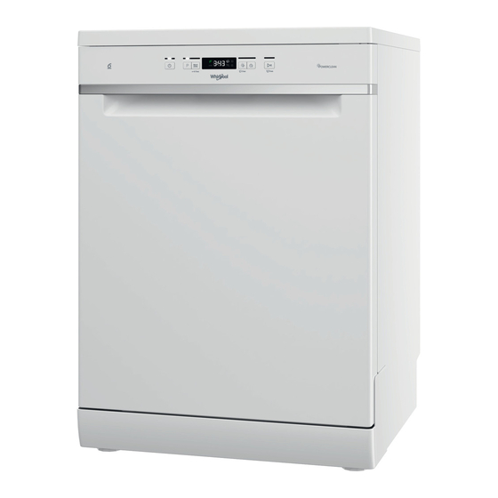
- Page 2 FEATURE DEFENITION 60 cm. Dishwasher Single Rack Washing Option Upper Rack Removability 14-Place Settings Flexible Washing Option Energy Efficient 8 Programs 9-liter Water Consumption Start-delay Function SRP: 32,998php...
-
Page 3: Main Feature
MAIN FEATURE... - Page 4 MAIN FEATURE...
- Page 5 ACCESSORIES Lower Basket Upper Basket...
-
Page 6: Technical Specifications
TECHNICAL SPECIFICATIONS SPECIFICATIONS WFC 3C26 EN Code 8003437205453 Contruction Type Free Standing Type of Control Electronics Wattage (W) 1750 Current (A) Voltage (V) Frequency (Hz) Electrical Supply Cord (cm) Plug Type Inlet hose length (cm) Outlet hose length (cm) Product Height... - Page 7 TECHNICAL SPECIFICATIONS SPECIFICATIONS WFC 3C26 Automatic Programs Max Temp water inlet (Celsius) Start delay option Cont. Start delay time max (hours) Digital Countdown Indicator Salt light indicator Rinse aid light indicator...
- Page 8 MODEL AND SERIAL NUMBER LOCATION Serial number and model can be found on the right side of the door...
-
Page 9: Pre-Installation Requirements
PRE-INSTALLATION REQUIREMENTS Required Power Outlet: ADVICE REGARDING THE FIRST TIME USE After installation, remove the stoppers from the racks and the retaining elastic elements from the upper rack. -
Page 10: Component Access
COMPONENT ACCESS Upper Rack Cutlery Rack Foldable Flaps Upper Rack Height Adjuster Upper Spray Arm Lower Rack Lower Spray Arm Filter Assembly Salt Reservoir Detergent and Rinse Aid Dispenser Model and Serial Control Panel... - Page 11 COMPONENT ACCESS On-Off/Reset Button Tablet tab Indicator Program Selection Button Closed water tap Indicator Multizone Button / Key Lock Indicator Rinse Aid refill Indicator Light Eco Program Indicator Salt Refill Indicator Key Lock Indicator Sani Rinse Button Indicator Display Delay Button Program number Start/Pause with Indicator/ Drain out...
-
Page 12: Operational Requirements
OPERATIONAL REQUIREMENTS FIRST TIME USE FILLING THE SALT RESERVOIR The use of salt prevents the formation of LIMESCALE on the dishes and on the machine’s functional components. • It is important that the salt reservoir be never empty. • It is important to set the water hardness. The salt reservoir is located in the lower part of the dishwasher (see PROGRAMS DESCRIPTION) and should be filled when the SALT REFILL indicator light in the control panel is lit. - Page 13 OPERATIONAL REQUIREMENTS SETTING THE WATER HARDNESS To allow the water softener to work in a perfect way, it is essential that the water hardness setting is based on the actual water hardness in your house. The factory setting is for average (3) water hardness. •...
- Page 14 OPERATIONAL REQUIREMENTS FILLING THE RINSE AID DISPENSER Rinse aid makes dish DRYING easier. The rinse aid dispenser A should be filled when the RINSE AID REFILL indicator light in the control panel is lit. 1. Open the dispenser B by pressing and pulling up the tab on the lid. 2.
- Page 15 OPERATIONAL REQUIREMENTS ADJUSTING THE DOSAGE OF RINSE AID If you are not completely satisfied with the drying results, you can adjust the quantity of rinse aid used. • Switch the dishwasher on using the ON/OFF button. • Switch it off using the ON/OFF button. •...
- Page 16 OPERATIONAL REQUIREMENTS FILLING THE DETERGENT DISPENSER To open the detergent dispenser use the opening device A. Introduce the detergent into the dry dispenser B only. Place the amount of detergent for pre-washing directly inside the tub. 1.When measuring out the detergent Compartment B comprises a level showing the maximum quantity of liquid or powder detergent that can be added to each cycle.
-
Page 17: Programs Table
PROGRAMS TABLE... -
Page 18: Operational Description
OPERATIONAL DESCRIPTION... -
Page 19: Loading The Racks
LOADING THE RACKS... - Page 20 LOADING THE RACKS...
- Page 21 LOADING THE RACKS...
- Page 22 LOADING THE RACKS...
- Page 23 LOADING THE RACKS...
- Page 24 TECHNICAL MEMO Removing the door hinged. *When removing the Door Panel, we need to Remove first the plint panel. (Refer to image below) 1. Remove the Plint Panel by pulling both sides, Indicated at Arrow 1.
- Page 25 TECHNICAL MEMO Removing the door hinged. *You may incline the lower front side of the unit so that you will have easy access on the Central Control Unit. 2. Remove the 2 screw.
- Page 26 TECHNICAL MEMO Removing the door hinged. *Figure show an exploded view of the base. 1-2-3 Open the locks of the CCU. 4 - This set of wire/terminal is the connection between the CCU and the door. Remove the terminal by pulling (Be careful and keep in mind about the lock of the terminal.)
- Page 27 TECHNICAL MEMO Removing the door hinged. *You may now removed the screws of upper, left and right side panels.
- Page 28 TECHNICAL MEMO Removing the door hinged. *Remove the Foam Insulation. 1- Here is the screw of the door hinged.
- Page 29 TECHNICAL MEMO Removing the door hinged. 1-2 - Removed the Screws on both side of the door panel hinged. 3- Removed the screw on both sides of the door panel hinged (opposite side screw)
- Page 30 TECHNICAL MEMO Removing the door hinged. *The door is now detached to the unit.
- Page 31 TECHNICAL MEMO There is no Part number on manual for the following parts: *Main Board (Central control unit)
- Page 32 TECHNICAL MEMO There is no Part number on manual for the following parts: *Terminal Block...
- Page 33 TECHNICAL MEMO * Heating Coil Rating is 230Volts / 50Hz / 1800W...
-
Page 34: Warranty
WARRANTY 1 Year Warranty Parts and Services...
Need help?
Do you have a question about the WFC 3C26 and is the answer not in the manual?
Questions and answers